1997 MERCEDES-BENZ ML320 air condition
[x] Cancel search: air conditionPage 2658 of 4133
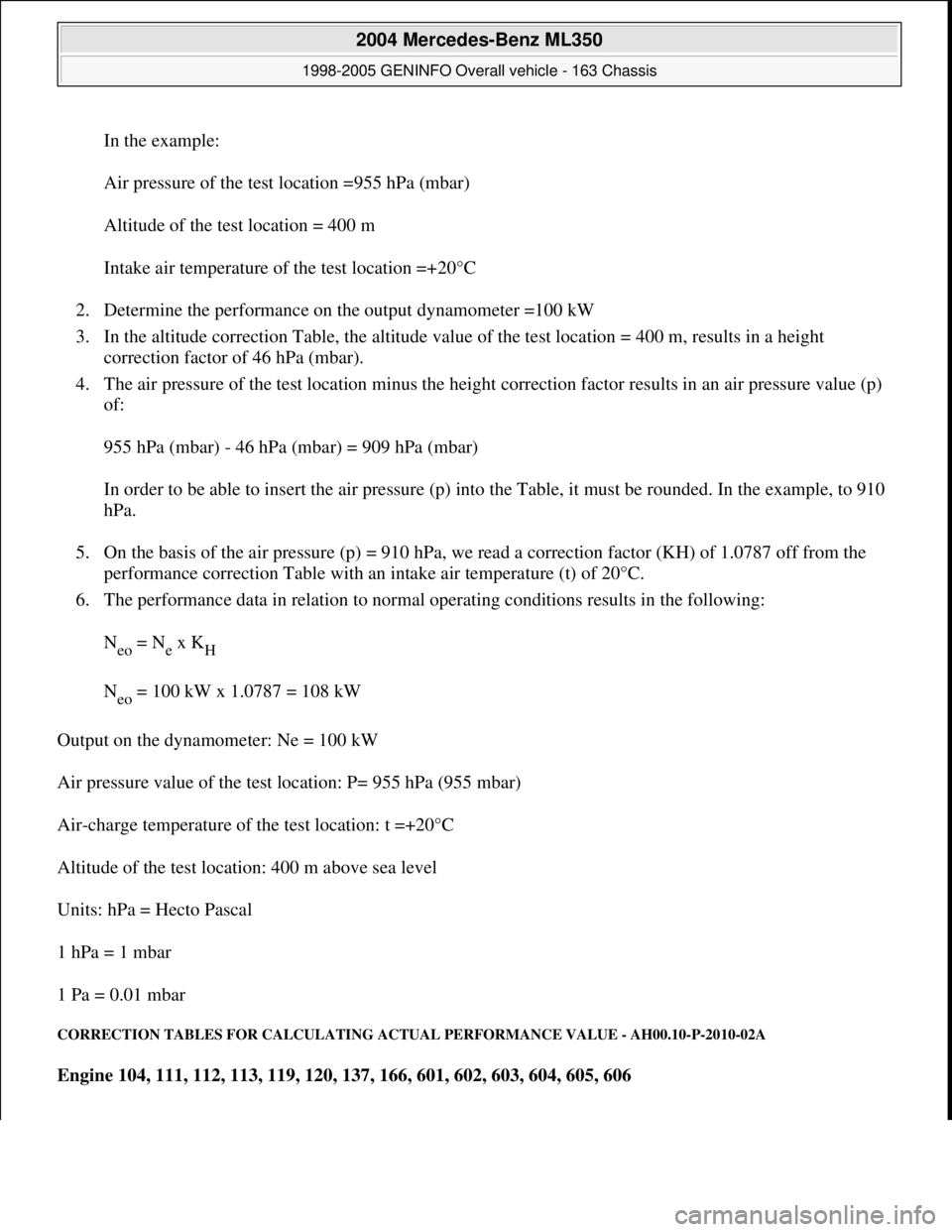
In the example:
Air pressure of the test location =955 hPa (mbar)
Altitude of the test location = 400 m
Intake air temperature of the test location =+20°C
2. Determine the performance on the output dynamometer =100 kW
3. In the altitude correction Table, the altitude value of the test location = 400 m, results in a height
correction factor of 46 hPa (mbar).
4. The air pressure of the test location minus the height correction factor results in an air pressure value (p)
of:
955 hPa (mbar) - 46 hPa (mbar) = 909 hPa (mbar)
In order to be able to insert the air pressure (p) into the Table, it must be rounded. In the example, to 910
hPa.
5. On the basis of the air pressure (p) = 910 hPa, we read a correction factor (KH) of 1.0787 off from the
performance correction Table with an intake air temperature (t) of 20°C.
6. The performance data in relation to normal operating conditions results in the following:
N
eo = Ne x KH
N
eo = 100 kW x 1.0787 = 108 kW
Output on the dynamometer: Ne = 100 kW
Air pressure value of the test location: P= 955 hPa (955 mbar)
Air-charge temperature of the test location: t =+20°C
Altitude of the test location: 400 m above sea level
Units: hPa = Hecto Pascal
1 hPa = 1 mbar
1 Pa = 0.01 mbar
CORRECTION TABLES FOR CALCULATING ACTUAL PERFORMANCE VALUE - AH00.10-P-2010-02A
Engine 104, 111, 112, 113, 119, 120, 137, 166, 601, 602, 603, 604, 605, 606
2004 Mercedes-Benz ML350
1998-2005 GENINFO Overall vehicle - 163 Chassis
me
Saturday, October 02, 2010 3:47:44 PMPage 13 © 2006 Mitchell Repair Information Company, LLC.
Page 2659 of 4133
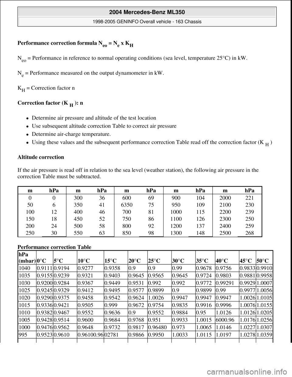
Performance correction formula Neo = Nex KH
Neo = Performance in reference to normal operating conditions (sea level, temperature 25°C) in kW.
Ne = Performance measured on the output dynamometer in kW.
K
H = Correction factor n
Correction factor (K
H ): n
Determine air pressure and altitude of the test location
Use subsequent altitude correction Table to correct air pressure
Determine air-charge temperature.
Using these values and the subsequent performance correction Table read off the correction factor (K H )
Altitude correction
If the air pressure is read off in relation to the sea level (weather station), the following air pressure in the
correction Table must be subtracted.
Performance correction Table
mhPamhPamhPamhPamhPa
0
0 30036 60069 900104 2000221
50
6 35041 635075 950109 2100230
100
12 40046 70081 1000115 2200239
150
18 45052 75086 1100126 2300250
200
24 50058 80092 1200137 2400259
250
30 55063 85098 1300148 2500268
hPa
(mbar)
0°C5°C10°C15°C20°C25°C30°C35°C40°C45°C50°C
10400.91110.91940.92770.93580.90.90.990.96780.97560.98330.9910
10350.91550.92390.93210.94030.96450.95650.96450.97240.98030.98810.9958
10300.92000.92840.93670.94490.95310.9920.9920.97720.992910.99291.0007
10250.92450.93290.94120.94950.95770.98990.90.98990.990.99771.0056
10200.92900.93750.94580.95420.96241.00260.99470.99470.99471.00261.0105
10150.93360.94210.95050.9990.96720.97540.98350.99160.99961.00761.0155
10100.93820.94670.95520.96360.90.95520.98840.951.01261.01261.0205
10050.94280.95140.96000.96840.97680.9510.99331.00156000.961.01761.0256
10000.94760.95620.96480.97320.98170.964800.9731.00651.01461.02271.0307
9950.95230.96100.96100.96027810.98660.99501.00331.01151.01971.02781.0359
2004 Mercedes-Benz ML350
1998-2005 GENINFO Overall vehicle - 163 Chassis
me
Saturday, October 02, 2010 3:47:44 PMPage 14 © 2006 Mitchell Repair Information Company, LLC.
Page 2671 of 4133
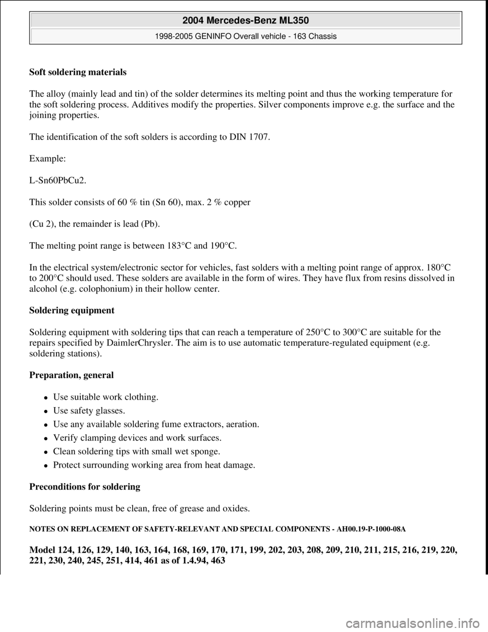
Soft soldering materials
The alloy (mainly lead and tin) of the solder determines its melting point and thus the working temperature for
the soft soldering process. Additives modify the properties. Silver components improve e.g. the surface and the
joining properties.
The identification of the soft solders is according to DIN 1707.
Example:
L-Sn60PbCu2.
This solder consists of 60 % tin (Sn 60), max. 2 % copper
(Cu 2), the remainder is lead (Pb).
The melting point range is between 183°C and 190°C.
In the electrical system/electronic sector for vehicles, fast solders with a melting point range of approx. 180°C
to 200°C should used. These solders are available in the form of wires. They have flux from resins dissolved in
alcohol (e.g. colophonium) in their hollow center.
Soldering equipment
Soldering equipment with soldering tips that can reach a temperature of 250°C to 300°C are suitable for the
repairs specified by DaimlerChrysler. The aim is to use automatic temperature-regulated equipment (e.g.
soldering stations).
Preparation, general
Use suitable work clothing.
Use safety glasses.
Use any available soldering fume extractors, aeration.
Verify clamping devices and work surfaces.
Clean soldering tips with small wet sponge.
Protect surrounding working area from heat damage.
Preconditions for soldering
Soldering points must be clean, free of grease and oxides.
NOTES ON REPLACEMENT OF SAFETY-RELEVANT AND SPECIAL COMPONENTS - AH00.19-P-1000-08A
Model 124, 126, 129, 140, 163, 164, 168, 169, 170, 171, 199, 202, 203, 208, 209, 210, 211, 215, 216, 219, 220,
221, 230, 240, 245, 251, 414, 461 as of 1.4.94, 463
2004 Mercedes-Benz ML350
1998-2005 GENINFO Overall vehicle - 163 Chassis
me
Saturday, October 02, 2010 3:47:44 PMPage 26 © 2006 Mitchell Repair Information Company, LLC.
Page 2678 of 4133
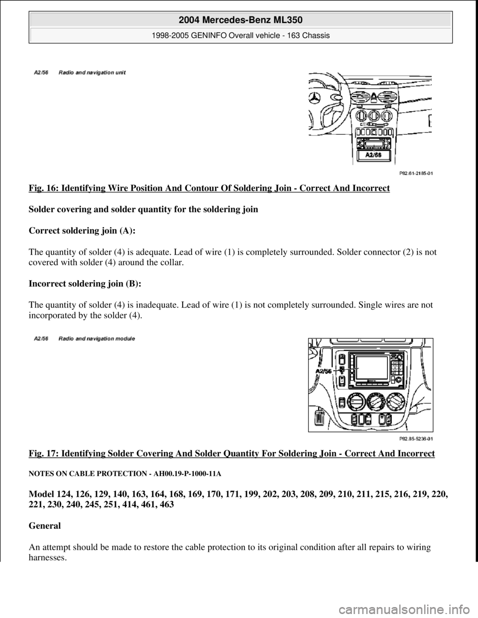
Fig. 16: Identifying Wire Position And Contour Of Soldering Join - Correct And Incorrect
Solder covering and solder quantity for the soldering join
Correct soldering join (A):
The quantity of solder (4) is adequate. Lead of wire (1) is completely surrounded. Solder connector (2) is not
covered with solder (4) around the collar.
Incorrect soldering join (B):
The quantity of solder (4) is inadequate. Lead of wi re (1) is not completely surrounded. Single wires are not
incorporated by the solder (4).
Fig. 17: Identifying Solder Covering A nd Solder Quantity For Soldering Join
- Correct And Incorrect
NOTES ON CABLE PROTECTION - AH00.19-P-1000-11A
Model 124, 126, 129, 140, 163, 164, 168, 169, 170, 171, 199, 202, 203, 208, 209, 210, 211, 215, 216, 219, 220,
221, 230, 240, 245, 251, 414, 461, 463
General
An attempt should be made to restor e the cable protection to its original condition after all repairs to wiring
harnesses.
2004 Mercedes-Benz ML350
1998-2005 GENINFO Overall vehicle - 163 Chassis
me
Saturday, October 02, 2010 3:47:44 PMPage 33 © 2006 Mitchell Repair Information Company, LLC.
Page 2679 of 4133
In areas exposed to particularly high stresses (dampness, scouring), additional safety precautions may however
be required.
The following measures are recommended depending on the application.
Protect repair area using:
Heat-shrinkable tube
Corrugated tube
Wrapping with fabric tape
Spaghetti insulation
BASIC KNOWLEDGE
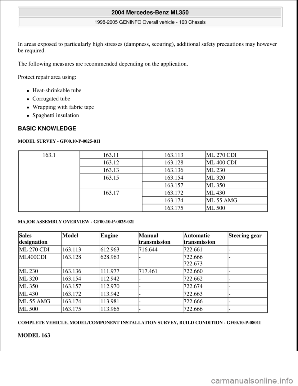
MODEL SURVEY - GF00.10-P-0025-01I
MAJOR ASSEMBLY OVERVIEW - GF00.10-P-0025-02I
COMPLETE VEHICLE, MODEL/COMPONENT INSTALLATION SURVEY, BUILD CONDITION - GF00.10-P-0801I
MODEL 163
163.1163.11163.113ML 270 CDI
163.12163.128ML 400 CDI
163.13163.136ML 230
163.15163.154ML 320
163.157ML 350
163.17163.172ML 430
163.174ML 55 AMG
163.175ML 500
Sales
designationModelEngineManual
transmissionAutomatic
transmissionSteering gear
ML 270 CDI163.113612.963716.644722.661-
ML400CDI163.128628.963-722.666
722.673-
ML 230163.136111.977717.461722.660-
ML 320163.154112.942-722.662-
ML 350163.157112.970-722.674-
ML 430163.172113.942-722.663-
ML 55 AMG163.174113.981-722.666-
ML 500163.175113.965-722.666-
2004 Mercedes-Benz ML350
1998-2005 GENINFO Overall vehicle - 163 Chassis
me
Saturday, October 02, 2010 3:47:44 PMPage 34 © 2006 Mitchell Repair Information Company, LLC.
Page 2842 of 4133
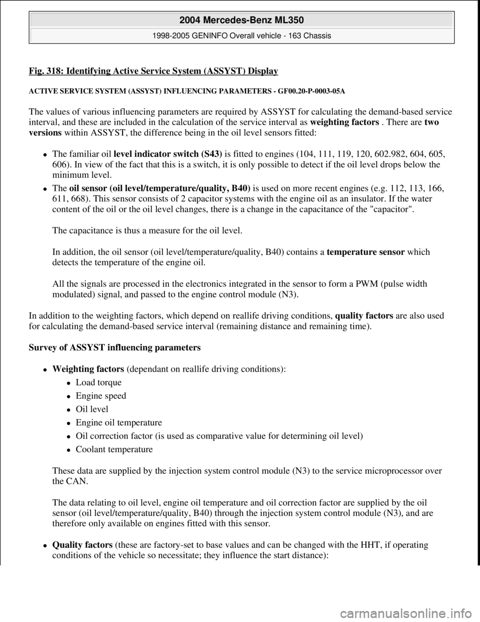
Fig. 318: Identifying Active Service System (ASSYST) Display
ACTIVE SERVICE SYSTEM (ASSYST) INFLUENCING PARAMETERS - GF00.20-P-0003-05A
The values of various influencing parameters are required by ASSYST for calculating the demand-based service
interval, and these are included in the calculation of the service interval as weighting factors . There are two
versions within ASSYST, the difference being in the oil level sensors fitted:
The familiar oil level indicator switch (S43) is fitted to engines (104, 111, 119, 120, 602.982, 604, 605,
606). In view of the fact that this is a switch, it is only possible to detect if the oil level drops below the
minimum level.
The oil sensor (oil level/temperature/quality, B40) is used on more recent engines (e.g. 112, 113, 166,
611, 668). This sensor consists of 2 capacitor systems with the engine oil as an insulator. If the water
content of the oil or the oil level changes, there is a change in the capacitance of the "capacitor".
The capacitance is thus a measure for the oil level.
In addition, the oil sensor (oil level/temperature/quality, B40) contains a temperature sensor which
detects the temperature of the engine oil.
All the signals are processed in the electronics integrated in the sensor to form a PWM (pulse width
modulated) signal, and passed to the engine control module (N3).
In addition to the weighting factors, which depend on reallife driving conditions, quality factors are also used
for calculating the demand-based service interval (remaining distance and remaining time).
Survey of ASSYST influencing parameters
Weighting factors (dependant on reallife driving conditions):
Load torque
Engine speed
Oil level
Engine oil temperature
Oil correction factor (is used as comparative value for determining oil level)
Coolant temperature
These data are supplied by the injection system control module (N3) to the service microprocessor over
the CAN.
The data relating to oil level, engine oil temperature and oil correction factor are supplied by the oil
sensor (oil level/temperature/quality, B40) through the injection system control module (N3), and are
therefore only available on engines fitted with this sensor.
Quality factors (these are factory-set to base values and can be changed with the HHT, if operating
conditions of the vehicle so necessitate; they influence the start distance):
2004 Mercedes-Benz ML350
1998-2005 GENINFO Overall vehicle - 163 Chassis
me
Saturday, October 02, 2010 3:47:47 PMPage 197 © 2006 Mitchell Repair Information Company, LLC.
Page 2844 of 4133
ACTIVE SERVICE SYSTEM (ASSY ST) FUNCTION - GF00.20-P-0003A
MODEL 129 with ENGINE 112, 113
MODEL 163 with ENGINE 112, 113, 612
MODEL 168 with ENGINE 166, 668
MODEL 202 with ENGINE 112, 113, 611
MODEL 208 with ENGINE 112, 113
MODEL 210 with ENGINE 112, 113, 611, 612, 613
General
The "Active service system (ASSYST)" draws the attent ion of the driver to a service which is due.
ASSYST is a demand-activated engine oil service system. In other words, in addition to the pure time and
distance criterion, various factors are taken into account for calculating the demand-oriented service intervals.
These are on the one hand quality factors which are c oded with the HHT, and on the other hand weighting
factors which take into account driving conditions and thus actual wear and tear.
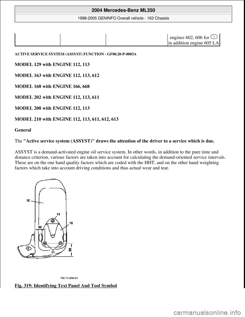
Fig. 319: Identifying Text Panel And Tool Symbol
engines 602, 606 for
in addition engine 605 LA
2004 Mercedes-Benz ML350
1998-2005 GENINFO Overall vehicle - 163 Chassis
me
Saturday, October 02, 2010 3:47:47 PMPage 199 © 2006 Mitchell Repair Information Company, LLC.
Page 2848 of 4133
REMAINING DISTANCE FUNCTION - GF00.20-P-2007A
MODEL 129 as of 1.6.97
MODEL 140 as of 1.6.97
MODEL 163
MODEL 168
MODEL 170 as of 1.6.97
MODEL 202 as of 1.6.97
MODEL 208 up to 31.7.99
MODEL 210 as of 1.3.97 up to 30.6.99
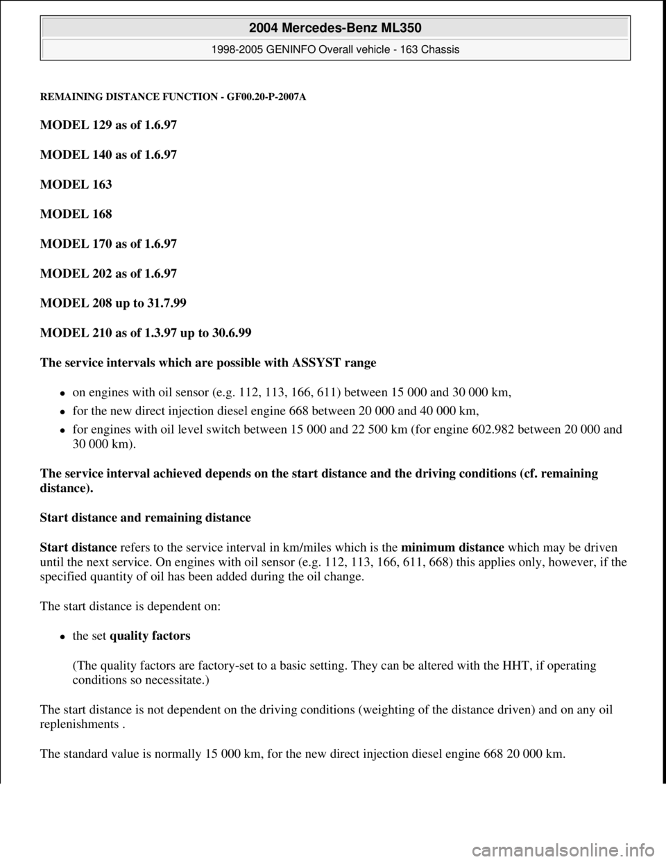
The service intervals which are possible with ASSYST range
on engines with oil sensor (e.g. 112, 113, 166, 611) between 15 000 and 30 000 km,
for the new direct injection diesel engine 668 between 20 000 and 40 000 km,
for engines with oil level switch between 15 000 and 22 500 km (for engine 602.982 between 20 000 and
30 000 km).
The service interval achieved depends on the start distance and the driving conditions (cf. remaining
distance).
Start distance and remaining distance
Start distance refers to the service interval in km/miles which is the minimum distance which may be driven
until the next service. On engines with oil sensor (e.g. 112, 113, 166, 611, 668) this applies only, however, if the
specified quantity of oil has been added during the oil change.
The start distance is dependent on:
the set quality factors
(The quality factors are factory-set to a basic setting. They can be altered with the HHT, if operating
conditions so necessitate.)
The start distance is not dependent on the driving conditions (weighting of the distance driven) and on any oil
replenishments .
The standard value is normall
y 15 000 km, for the new direct injection diesel engine 668 20 000 km.
2004 Mercedes-Benz ML350
1998-2005 GENINFO Overall vehicle - 163 Chassis
me
Saturday, October 02, 2010 3:47:47 PMPage 203 © 2006 Mitchell Repair Information Company, LLC.