1997 MERCEDES-BENZ ML320 air condition
[x] Cancel search: air conditionPage 3225 of 4133
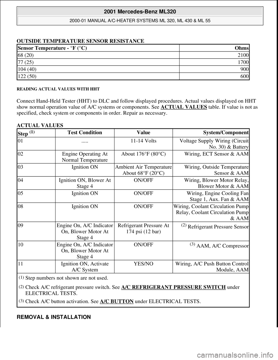
OUTSIDE TEMPERATURE SENSOR RESISTANCE
READING ACTUAL VALUES WITH HHT
Connect Hand-Held Tester (HHT) to DLC and follow displayed procedures. Actual values displayed on HHT
show normal operation value of A/C systems or components. See ACTUAL VALUES
table. If value is not as
specified, check system or components in order. Repair as necessary.
ACTUAL VALUES
REMOVAL & INSTALLATION
Sensor Temperature - °F (°C)Ohms
68 (20)2100
77 (25)1700
104 (40)900
122 (50)600
Step (1) Test ConditionValueSystem/Component
01.....11-14 VoltsVoltage Supply Wiring (Circuit
No. 30) & Battery
02Engine Operating At
Normal TemperatureAbout 176°F (80°C)Wiring, ECT Sensor & AAM
03Ignition ONAmbient Air Temperature
About 68°F (20°C)Wiring, Outside Temperature
Sensor & AAM
04Ignition ON, Blower At
Stage 4ON/OFFWiring, Blower Motor Relay,
Blower Motor & AAM
05Ignition ONON/OFFWiring, Engine Cooling Fan
Stage 1, Aux. Fan & AAM
08Ignition ONON/OFFWiring, Coolant Circulation Pump
Relay, Coolant Circulation Pump
& AAM
09Engine On, A/C Indicator
On, Blower Motor At
Stage 4Refrigerant Pressure At
174 psi (12 bar)(2) Refrigerant Pressure Sensor
10Engine On, A/C Indicator
On, Blower Motor At
Stage 4ON/OFF(3) AAM, A/C Compressor
11Ignition ON, Activate
A/C SystemYES/NOWiring, A/C Push Button Control
Module, AAM
(1)Step numbers not shown are not used.
(2)Check A/C refrigerant pressure switch. See A/C REFRIGERANT PRESSURE SWITCH under
ELECTRICAL TESTS.
(3)Check A/C button activation. See A/C BUTTON under ELECTRICAL TESTS.
2001 Mercedes-Benz ML320
2000-01 MANUAL A/C-HEATER SYSTEMS ML 320, ML 430 & ML 55
me
Saturday, October 02, 2010 3:25:10 PMPage 14 © 2006 Mitchell Repair Information Company, LLC.
Page 3245 of 4133
1998-2005 HVAC
Climate Control - 163 Chassis
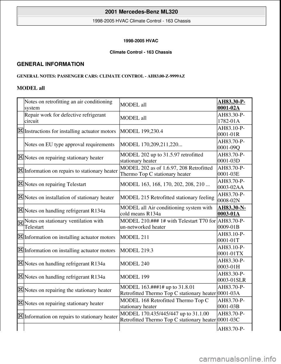
GENERAL INFORMATION
GENERAL NOTES: PASSENGER CARS: CLIMATE CONTROL - AH83.00-Z-9999AZ
MODEL all
Notes on retrofitting an air conditioning
systemMODEL allAH83.30-P-
0001-02A
Repair work for defective refrigerant
circuitMODEL allAH83.30-P-
1782-01A
Instructions for installing actuator motorsMODEL 199,230.4AH83.10-P-
0001-01R
Notes on EU type approval requirementsMODEL 170,209,211,220...AH83.70-P-
0001-09Q
Notes on repairing stationary heaterMODEL 202 up to 31.5.97 retrofitted
stationary heaterAH83.70-P-
0001-03D
Information on repairs to stationary heaterMODEL 202 as of 1.6.97, 208 Retrofitted
Thermo Top C stationary heaterAH83.70-P-
0001-03E
Notes on repairing TelestartMODEL 163, 168, 170, 202, 208, 210 ...AH83.70-P-
0003-02AA
Notes on installation of stationary heaterMODEL 215 Retrofitted stationary feelingAH83.70-P-
0008-02N
Notes on handling refrigerant R134aMODEL all Air conditioning system with
cold means R134aAH83.30-N-
0003-01A
Notes on stationary ventilation with
TelestartMODEL 210.### 1# with Telestart T70 for
un-networked heaterAH83.70-P-
0009-01B
Information on installing actuator motorsMODEL 211AH83.10-P-
0001-01T
Information on installing actuator motorsMODEL 219.3AH83.10-P-
0001-01TX
Notes on handling refrigerant R134aMODEL 240AH83.30-P-
0003-01H
Notes on handling refrigerant R134aMODEL 199AH83.30-P-
0003-01SLR
Notes on repairing the stationary heaterMODEL 163.###1# up to 31.8.01
Retrofitted Thermo Top C stationary heaterAH83.70-P-
0001-03A
Notes on repairing stationary heaterMODEL 168 Retrofitted Thermo Top C
stationary heaterAH83.70-P-
0001-03B
Information on repairs to stationary heaterMODEL 170.435/445/447 up to 31.1.00
Retrofitted Thermo Top C stationary heaterAH83.70-P-
0001-03C
AH83.70-P-
2001 Mercedes-Benz ML320
1998-2005 HVAC Climate Control - 163 Chassis
2001 Mercedes-Benz ML320
1998-2005 HVAC Climate Control - 163 Chassis
me
Saturday, October 02, 2010 3:23:14 PMPage 1 © 2006 Mitchell Repair Information Company, LLC.
me
Saturday, October 02, 2010 3:24:17 PMPage 1 © 2006 Mitchell Repair Information Company, LLC.
Page 3246 of 4133
Information on repairs to stationary heaterMODEL 170.444/449/4650001-03CA
Information on repairs to stationary heaterMODEL 210...AH83.70-P-
0001-03F
Notes on repairing the stationary heaterMODEL 163.###1# as of 1.9.01
Retrofitted Thermo Top C stationary heaterAH83.70-P-
0001-03I
Distinguishing features stationary heater/
stationary preheater/heater boosterMODEL 202.### 1# Webasto Thermo Top
C heaterAH83.70-P-
0003-01A
Distinguishing characteristics stationary
heater/ stationary preheater/heater boosterMODEL 210.###1# up to 31.5.00 Heater
Webasto Thermo Top CAH83.70-P-
0003-01B
Distinguishing features stationary
heater/stationary preheater/heater boosterMODEL 168.###1# Heater Webasto
Thermo Top CAH83.70-P-
0003-01C
Notes on repairing telestartMODEL 168,170, 202 as of 1.6.97,
208,210 More retrofitted telestart T60AH83.70-P-
0003-02A
Notes on repairing telestartMODEL 202 up to 31.5.97 Telestart T60 in
retrofitted stationary heaterAH83.70-P-
0003-02B
Notes on repairing telestartMODEL 163 Telestart T60 in retrofitted
stationary heaterAH83.70-P-
0003-02C
Notes on repairing TelestartMODEL 215, 220AH83.70-P-
0003-02M
Notes on differentiating characteristics of
TelestartMODEL 163, 168, 170, 202, 210 ...AH83.70-P-
0003-03A
Notes on installation of timerMODEL 163, 168, 170, 202, 208 ...AH83.70-P-
0008-01A
Notes on installing stationary heater
MODEL 163, 168, 170, 202, 203, 208,
209, 210, 211, 220, 414 Retrofitted
stationary heaterAH83.70-P-
0008-02A
Notes on installing stationary heaterMODEL 450.3 /4 (except, 450.418)AH83.70-P-
0008-02SM
Notes for timer and/or Telestart
MODELS 163.###1A as of 145270,
163.### 1X as of 708319 Retrofitted
stationary heaterAH83.70-P-
0008-03A
Notes for stationary ventilation with
TelestartMODEL 163.###, 168.###, 170.###,
202.###, 208.###1# Telestart T70AH83.70-P-
0009-01A
Notes on Telestart with GSM antennaMODEL 168, 170, 202, 208.3, 210
Telestart T70AH83.70-P-
0009-02A
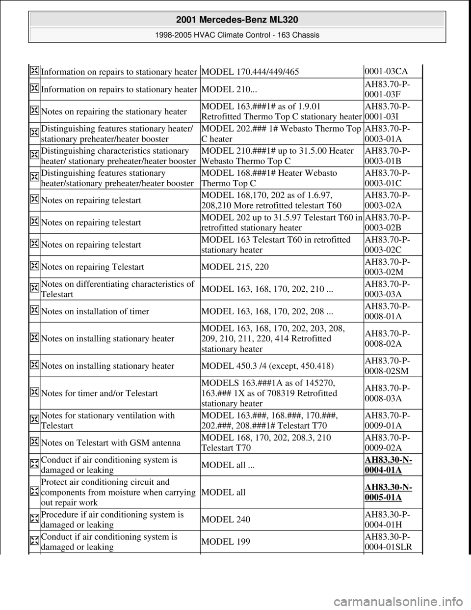
Conduct if air conditioning system is
damaged or leakingMODEL all ...AH83.30-N-
0004-01A
Protect air conditioning circuit and
components from moisture when carrying
out repair work
MODEL allAH83.30-N-
0005-01A
Procedure if air conditioning system is
damaged or leakingMODEL 240AH83.30-P-
0004-01H
Conduct if air conditioning system is
damaged or leakingMODEL 199AH83.30-P-
0004-01SLR
2001 Mercedes-Benz ML320
1998-2005 HVAC Climate Control - 163 Chassis
me
Saturday, October 02, 2010 3:23:14 PMPage 2 © 2006 Mitchell Repair Information Company, LLC.
Page 3247 of 4133
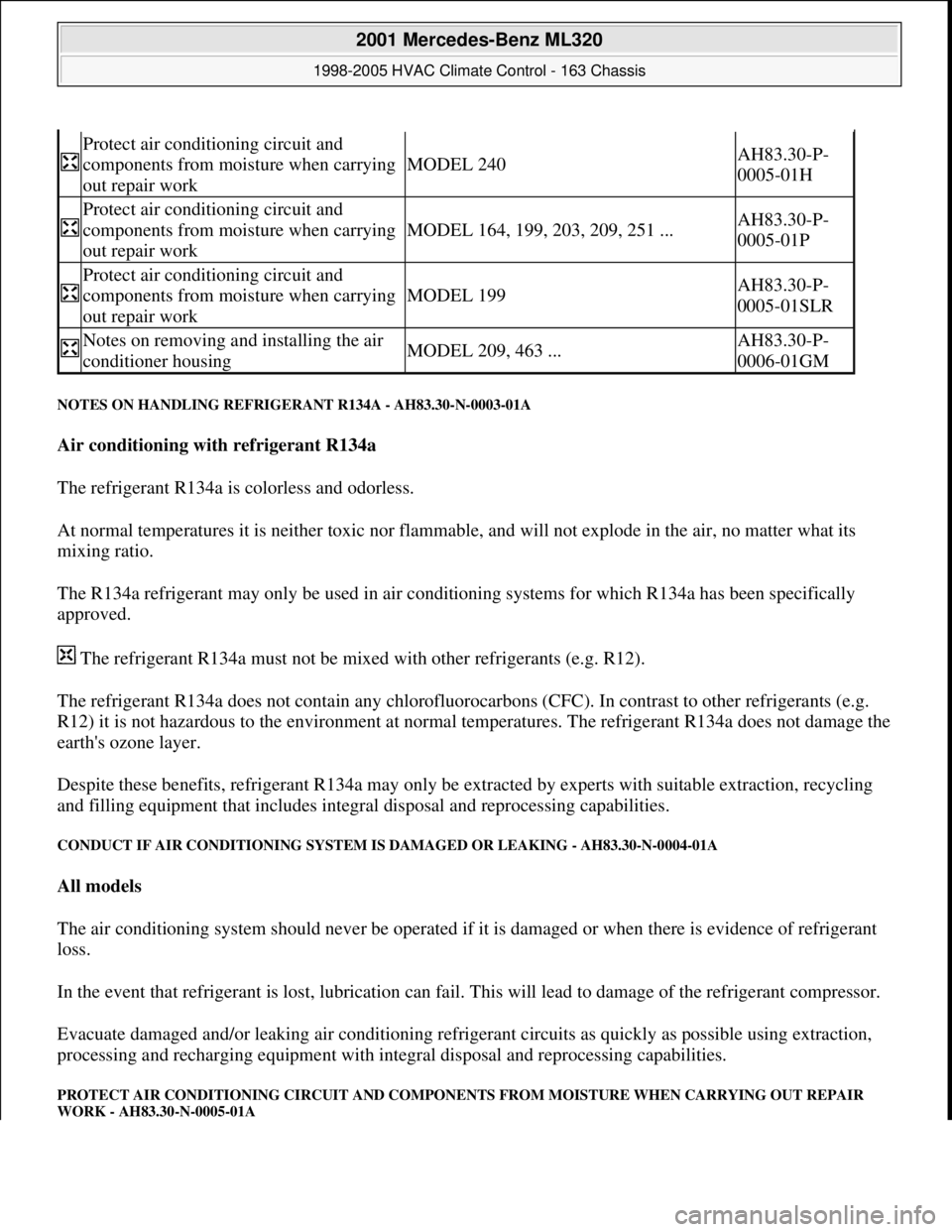
NOTES ON HANDLING REFRIGERANT R134A - AH83.30-N-0003-01A
Air conditioning with refrigerant R134a
The refrigerant R134a is colorless and odorless.
At normal temperatures it is neither toxic nor flammable, and will not explode in the air, no matter what its
mixing ratio.
The R134a refrigerant may only be used in air conditioning systems for which R134a has been specifically
approved.
The refrigerant R134a must not be mixed with other refrigerants (e.g. R12).
The refrigerant R134a does not contain any chlorofluorocarbons (CFC). In contrast to other refrigerants (e.g.
R12) it is not hazardous to the environment at normal temperatures. The refrigerant R134a does not damage the
earth's ozone layer.
Despite these benefits, refrigerant R134a may only be extracted by experts with suitable extraction, recycling
and filling equipment that includes integral disposal and reprocessing capabilities.
CONDUCT IF AIR CONDITIONING SYSTEM IS DAMAGED OR LEAKING - AH83.30-N-0004-01A
All models
The air conditioning system should never be operated if it is damaged or when there is evidence of refrigerant
loss.
In the event that refrigerant is lost, lubrication can fail. This will lead to damage of the refrigerant compressor.
Evacuate damaged and/or leaking air conditioning refrigerant circuits as quickly as possible using extraction,
processing and recharging equipment with integral disposal and reprocessing capabilities.
PROTECT AIR CONDITIONING CIRCUIT AND COMPONENTS FROM MOISTURE WHEN CARRYING OUT REPAIR
WORK - AH83.30-N-0005-01A
Protect air conditioning circuit and
components from moisture when carrying
out repair work
MODEL 240AH83.30-P-
0005-01H
Protect air conditioning circuit and
components from moisture when carrying
out repair work
MODEL 164, 199, 203, 209, 251 ...AH83.30-P-
0005-01P
Protect air conditioning circuit and
components from moisture when carrying
out repair work
MODEL 199AH83.30-P-
0005-01SLR
Notes on removing and installing the air
conditioner housingMODEL 209, 463 ...AH83.30-P-
0006-01GM
2001 Mercedes-Benz ML320
1998-2005 HVAC Climate Control - 163 Chassis
me
Saturday, October 02, 2010 3:23:14 PMPage 3 © 2006 Mitchell Repair Information Company, LLC.
Page 3248 of 4133
All models fitted with air conditioning
Do not carry repair operations out on the air conditioning circuit in the open air during moist weather.
Moisture in the refrigerant circuit reduces the system's refrigeration output and leads to damage to the
components. The acidic substances produced by moisture within the system decompose the desiccant in the
fluid reservoir and damage the entire system.
After separating/unscrewing refrigerant lines, immediately seal off the connection openings so that they are
airproof using suitable stop plugs (parts kit).
Replace the fluid reservoir every time you open up the refrigeration circuit.
Always store all spare components in a dry, sealed-off area. Do not remove stop plugs in new components until
just before they are installed. Use special care when handling the receiver/dryer with its integral desiccation
unit.
When a receiver/dryer is left open, the dryer unit quickly becomes saturated with moisture, rendering it useless.
Check drier cartridge packaging for damage. Dispose of drier cartridges with damaged packaging.
Install the desiccant cartridge no later than 20 minutes after opening the packaging.
Further protection against moisture is provided by carefully evacuating the air conditioning system following
repair operations. By generating vacuum in the system, the evacuation process removes any moisture that might
have penetrated into the system.
NOTES ON RETROFITTING AN AIR CONDITIONING SYSTEM - AH83.30-P-0001-02A
Do not remove the plugs on any of the components until immediately prior to installation.
Fit all AC lines with new sealing rings. Coat thread and sealing rings with compressor oil.
BASIC KNOWLEDGE
VENTILATION, FUNCTION - GF83.10-P-2000GH
MODEL 163 up to 31.8.01
2001 Mercedes-Benz ML320
1998-2005 HVAC Climate Control - 163 Chassis
me
Saturday, October 02, 2010 3:23:14 PMPage 4 © 2006 Mitchell Repair Information Company, LLC.
Page 3250 of 4133
VENTILATION, FUNCTION - GF83.10-P-2000GI
MODEL 163 as of 1.9.01 with CODE (580a) Automatic air conditioning
Air distribution duct
The air distribution duct and the existing air outlets for ventilating the vehicle interior are shown by the arrows.
Temperature-controlled air flows out of all the air outlets (red/blue arrows).
Rear vent, location/task/function GF83.10-P-
2143GC
Defroster vent, location/task/function GF83.10-P-
2144GC
Center nozzle, location/task/function GF83.10-P-
2149GC
Lateral nozzle, location/task/function GF83.10-P-
2150GC
Front footwell air outlet, location/task/function GF83.10-P-
2145GC
Rear footwell air outlet, location/task/function GF83.10-P-
2146GC
Blower, location / task / design / function GF83.10-P-
2102GC
Series resistor group, location/task/function GF83.10-P-
2161GC
Dust filter, location / task / function GF83.10-P-
2142GH
Fresh air/recirculation flap, location / task / function GF83.20-P-
2111GC
Recirculating air switch, location/task/design/ function GF83.10-P-
2117GH
Fresh air/recirculation flap actuator motor, location /
task / function GF83.30-P-
2116GC
Blower switch, location/task/design/function GF83.25-P-
2100GC
Air distribution switch, location/task/design/ function GF83.25-P-
2101GH
Heater housing position/task/function except in the case of
code 580GF83.20-P-
2110GC
Evaporator housing, location/task/function for code 580 onlyGF83.30-P-
2119GH
2001 Mercedes-Benz ML320
1998-2005 HVAC Climate Control - 163 Chassis
me
Saturday, October 02, 2010 3:23:14 PMPage 6 © 2006 Mitchell Repair Information Company, LLC.
Page 3251 of 4133
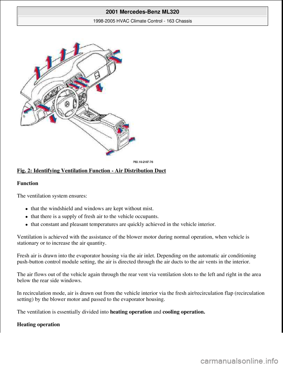
Fig. 2: Identifying Ventilation Function - Air Distribution Duct
Function
The ventilation system ensures:
that the windshield and windows are kept without mist.
that there is a supply of fresh air to the vehicle occupants.
that constant and pleasant temperatures are quickly achieved in the vehicle interior.
Ventilation is achieved with the assistance of the blower motor during normal operation, when vehicle is
stationary or to increase the air quantity.
Fresh air is drawn into the evaporator housing via the air inlet. Depending on the automatic air conditioning
push-button control module setting, the air is directed through the air ducts to the air vents in the interior.
The air flows out of the vehicle again through the rear vent via ventilation slots to the left and right in the area
below the rear side windows.
In recirculation mode, air is drawn out from the vehicle interior via the fresh air/recirculation flap (recirculation
setting) by the blower motor and passed to the evaporator housing.
The ventilation is essentially divided into heating operation and cooling operation.
Heating operation
2001 Mercedes-Benz ML320
1998-2005 HVAC Climate Control - 163 Chassis
me
Saturday, October 02, 2010 3:23:14 PMPage 7 © 2006 Mitchell Repair Information Company, LLC.
Page 3252 of 4133
Two main objectives are pursued in heating operation:
rapid heating and even control of in-car temperature
good visibility through windshield and front side windows
In the starting phase the headroom temperature is deliberately increased, in order to meet the passengers' initial
increased heat requirements. The temperature and the duration depend on the outside temperature and the in-car
temperature.
As far as good visibility is concerned, special control measures to accelerate defrosting of the windows are
taken during the starting phase, depending on the ambient conditions.
In closed-loop operation the footwell vents are mainly used to control the in-car temperature. The center nozzle
is fully closed. The defrosting control measures are reduced.
Cooling operation
During cooling operation the objective is to cool the interior rapidly and evenly control the temperature.
Window fogging is not usually a problem during maximum cooling operation and therefore does not require
special measures.
In the starting phase the headroom temperature is deliberately reduced. The temperature and the duration
depend on the outside temperature and the in-car temperature.
Furthermore, the cooling capacity can be reduced during subsequent operation since continuous partial
recirculating air operation can be achieved.
In closed-loop operation the center nozzles are mainly used to control the in-car temperature.
Bi-level operation (2-level operation)
In bi-level operation the temperature of the interior is controlled by a combination of the footwell nozzles and
the center nozzles.
The objective is to create stratification , which gives the passengers warm feet and a cooler head .
The air distribution shifts in the direction of heating or cooling operation depending on the controller status
trend.
Rear compartment ventilation
The rear compartment nozzles are supplied with temperature-controlled air by the front compartment automatic
air conditioning. The rear compartment nozzle outlet temperature can therefore not be separately controlled.
The air quantity and the air distribution are available as adjustable parameters. The passengers in the rear can
control the ventilation themselves usin
g appropriate buttons.
2001 Mercedes-Benz ML320
1998-2005 HVAC Climate Control - 163 Chassis
me
Saturday, October 02, 2010 3:23:14 PMPage 8 © 2006 Mitchell Repair Information Company, LLC.