Page 1961 of 4133
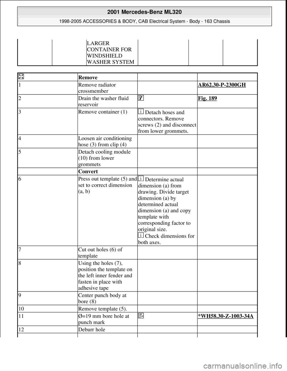
LARGER
CONTAINER FOR
WINDSHIELD
WASHER SYSTEM
Remove
1Remove radiator
crossmember AR62.30-P-2300GH
2Drain the washer fluid
reservoir Fig. 189
3Remove container (1) Detach hoses and
connectors. Remove
screws (2) and disconnect
from lower grommets.
4Loosen air conditioning
hose (3) from clip (4)
5Detach cooling module
(10) from lower
grommets
Convert
6Press out template (5) and
set to correct dimension
(a, b) Determine actual
dimension (a) from
drawing. Divide target
dimension (a) by
determined actual
dimension (a) and copy
template with
corresponding factor to
original size.
Check dimensions for
both axes.
7Cut out holes (6) of
template
8Using the holes (7),
position the template on
the left inner fender and
fasten in place with
adhesive tape
9Center punch body at
bore (8)
10Remove template (5).
11Ø=19 mm bore hole at
punch mark *WH58.30-Z-1003-34A
12Deburr hole
2001 Mercedes-Benz ML320
1998-2005 ACCESSORIES & BODY, CAB Electrical System - Body - 163 Chassis
me
Saturday, October 02, 2010 3:30:14 PMPage 466 © 2006 Mitchell Repair Information Company, LLC.
Page 2037 of 4133
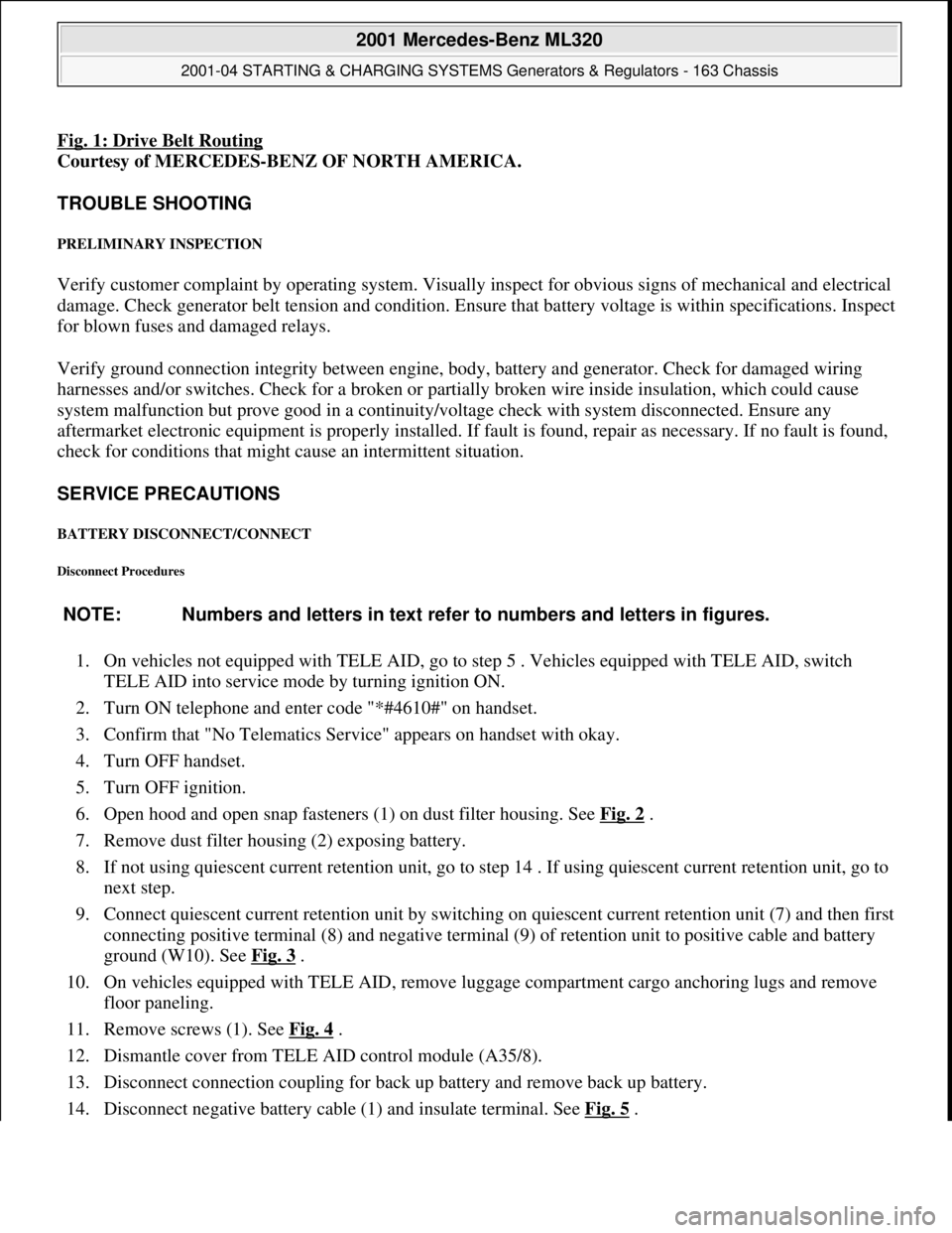
Fig. 1: Drive Belt Routing
Courtesy of MERCEDES-BENZ OF NORTH AMERICA.
TROUBLE SHOOTING
PRELIMINARY INSPECTION
Verify customer complaint by operating system. Visually inspect for obvious signs of mechanical and electrical
damage. Check generator belt tension and condition. Ensure that battery voltage is within specifications. Inspect
for blown fuses and damaged relays.
Verify ground connection integrity between engine, body, battery and generator. Check for damaged wiring
harnesses and/or switches. Check for a broken or partially broken wire inside insulation, which could cause
system malfunction but prove good in a continuity/voltage check with system disconnected. Ensure any
aftermarket electronic equipment is properly installed. If fault is found, repair as necessary. If no fault is found,
check for conditions that might cause an intermittent situation.
SERVICE PRECAUTIONS
BATTERY DISCONNECT/CONNECT
Disconnect Procedures
1. On vehicles not equipped with TELE AID, go to step 5 . Vehicles equipped with TELE AID, switch
TELE AID into service mode by turning ignition ON.
2. Turn ON telephone and enter code "*#4610#" on handset.
3. Confirm that "No Telematics Service" appears on handset with okay.
4. Turn OFF handset.
5. Turn OFF ignition.
6. Open hood and open snap fasteners (1) on dust filter housing. See Fig. 2
.
7. Remove dust filter housing (2) exposing battery.
8. If not using quiescent current retention unit, go to step 14 . If using quiescent current retention unit, go to
next step.
9. Connect quiescent current retention unit by switching on quiescent current retention unit (7) and then first
connecting positive terminal (8) and negative terminal (9) of retention unit to positive cable and battery
ground (W10). See Fig. 3
.
10. On vehicles equipped with TELE AID, remove luggage compartment cargo anchoring lugs and remove
floor paneling.
11. Remove screws (1). See Fig. 4
.
12. Dismantle cover from TELE AID control module (A35/8).
13. Disconnect connection coupling for back up battery and remove back up battery.
14. Disconnect ne
gative battery cable (1) and insulate terminal. See Fig. 5. NOTE: Numbers and letters in text refer to numbers and letters in figures.
2001 Mercedes-Benz ML320
2001-04 STARTING & CHARGING SYSTEMS Generators & Regulators - 163 Chassis
me
Saturday, October 02, 2010 3:20:31 PMPage 3 © 2006 Mitchell Repair Information Company, LLC.
Page 2048 of 4133

Fig. 8: Connecting Hand Held Tester Scan Tool To OBD-II Data Link Connector
Courtesy of MERCEDES-BENZ OF NORTH AMERICA.
ON-VEHICLE TESTING
WIRING CONTINUITY
1. Connect voltmeter between generator B+ terminal and ground. Voltmeter should indicate battery voltage.
If battery voltage is not indicated, check battery and check wiring between generator and battery for
corrosion, loose terminals, etc.
2. Turn ignition on and ensure instrument cluster charge indicator light (battery symbol) comes on. If light
does not come on, check wiring between generator and warning light, including indicator bulb.
GENERATOR OUTPUT
1. Ensure connections at battery and generator are clean and tight. Ensure generator, engine and body are
properly grounded. Ensure generator drive belt is properly adjusted and in good condition.
2. Connect load tester/ammeter as per tester manufacturer's instructions. Connect voltmeter leads to battery
terminals. See Fig. 9
. Start engine and run at 2200 RPM for V6 or 2500 RPM for V8. Adjust load tester
to obtain maximum generator output. DO NOT allow voltage to drop to less than 12.7 volts.
3. Maximum generator output should be within a few amps of generator rated output stamped on generator.
If output is not within a few amps of generator rated output, check generator diodes. See DIODE TEST
.
Replace
generator as necessary.
2001 Mercedes-Benz ML320
2001-04 STARTING & CHARGING SYSTEMS Generators & Regulators - 163 Chassis
me
Saturday, October 02, 2010 3:20:32 PMPage 14 © 2006 Mitchell Repair Information Company, LLC.
Page 2159 of 4133
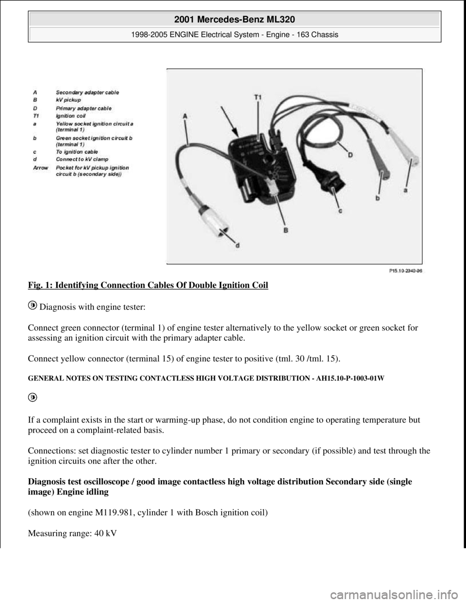
Fig. 1: Identifying Connection Cables Of Double Ignition Coil
Diagnosis with engine tester:
Connect green connector (terminal 1) of engine tester alternatively to the yellow socket or green socket for
assessing an ignition circuit with the primary adapter cable.
Connect yellow connector (terminal 15) of engine tester to positive (tml. 30 /tml. 15).
GENERAL NOTES ON TESTING CONTACTLESS HIGH VOLTAGE DISTRIBUTION - AH15.10-P-1003-01W
If a complaint exists in the start or warming-up phase, do not condition engine to operating temperature but
proceed on a complaint-related basis.
Connections: set diagnostic tester to cylinder number 1 primary or secondary (if possible) and test through the
ignition circuits one after the other.
Diagnosis test oscilloscope / good image contactless high voltage distribution Secondary side (single
image) Engine idling
(shown on engine M119.981, cylinder 1 with Bosch ignition coil)
Measurin
g range: 40 kV
2001 Mercedes-Benz ML320
1998-2005 ENGINE Electrical System - Engine - 163 Chassis
me
Saturday, October 02, 2010 3:18:54 PMPage 5 © 2006 Mitchell Repair Information Company, LLC.
Page 2165 of 4133
ME-SFI IGNITION SYSTEM FUNCTION DIAGRAM - GF15.12-P-0001-01A
Fig. 9: Identifying ME-SFI Ignition System Components - Engine 112
ME-SFI IGNITION SYSTEM FUNCTION DIAGRAM - GF15.12-P-0001-01B
Ignition coils, location GF15.10-P-3102-01A
Ignition coils, taskSupplying adequate
ignition energy in all
operating conditions for
the particular ignition
circuit.
Ignition coils, designOne double ignition coil
for each cylinder. Attached
to cylinder head cover.
Ignition coils, function GF15.10-P-3102-02A
2001 Mercedes-Benz ML320
1998-2005 ENGINE Electrical System - Engine - 163 Chassis
me
Saturday, October 02, 2010 3:18:54 PMPage 11 © 2006 Mitchell Repair Information Company, LLC.
Page 2176 of 4133
112.910 /911 /912 /913 /914 /916 /917 /920 /921 /922 /923 /940 /941 /942 /943 /944 /946 /947 /949 /953 /954 /95
ENGINE 113.940 /941 /942 /943 /948 /960 /961 /963 /965 /966 /967 /969
ENGINE 119.980 /981 /982 /985
ENGINE 120.982/983
ENGINE 137.970
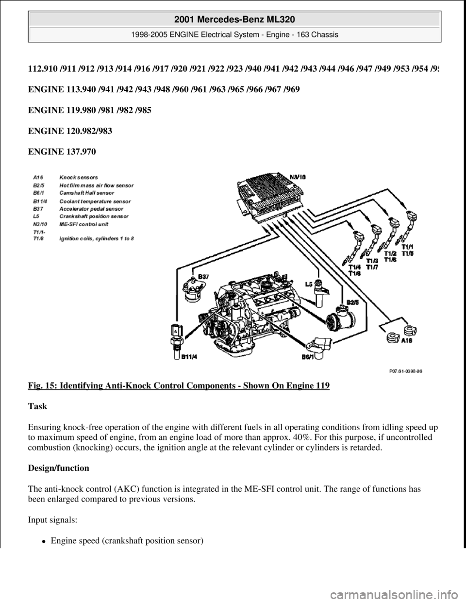
Fig. 15: Identifying Anti
-Knock Control Components - Shown On Engine 119
Task
Ensuring knock-free operation of the engine with different fuels in all operating conditions from idling speed up
to maximum speed of engine, from an engine load of more than approx. 40%. For this purpose, if uncontrolled
combustion (knocking) occurs, the ignition angle at the relevant cylinder or cylinders is retarded.
Design/function
The anti-knock control (AKC) function is integrated in the ME-SFI control unit. The range of functions has
been enlarged compared to previous versions.
Input signals:
Engine speed (crankshaft position sensor)
2001 Mercedes-Benz ML320
1998-2005 ENGINE Electrical System - Engine - 163 Chassis
me
Saturday, October 02, 2010 3:18:54 PMPage 22 © 2006 Mitchell Repair Information Company, LLC.
Page 2203 of 4133
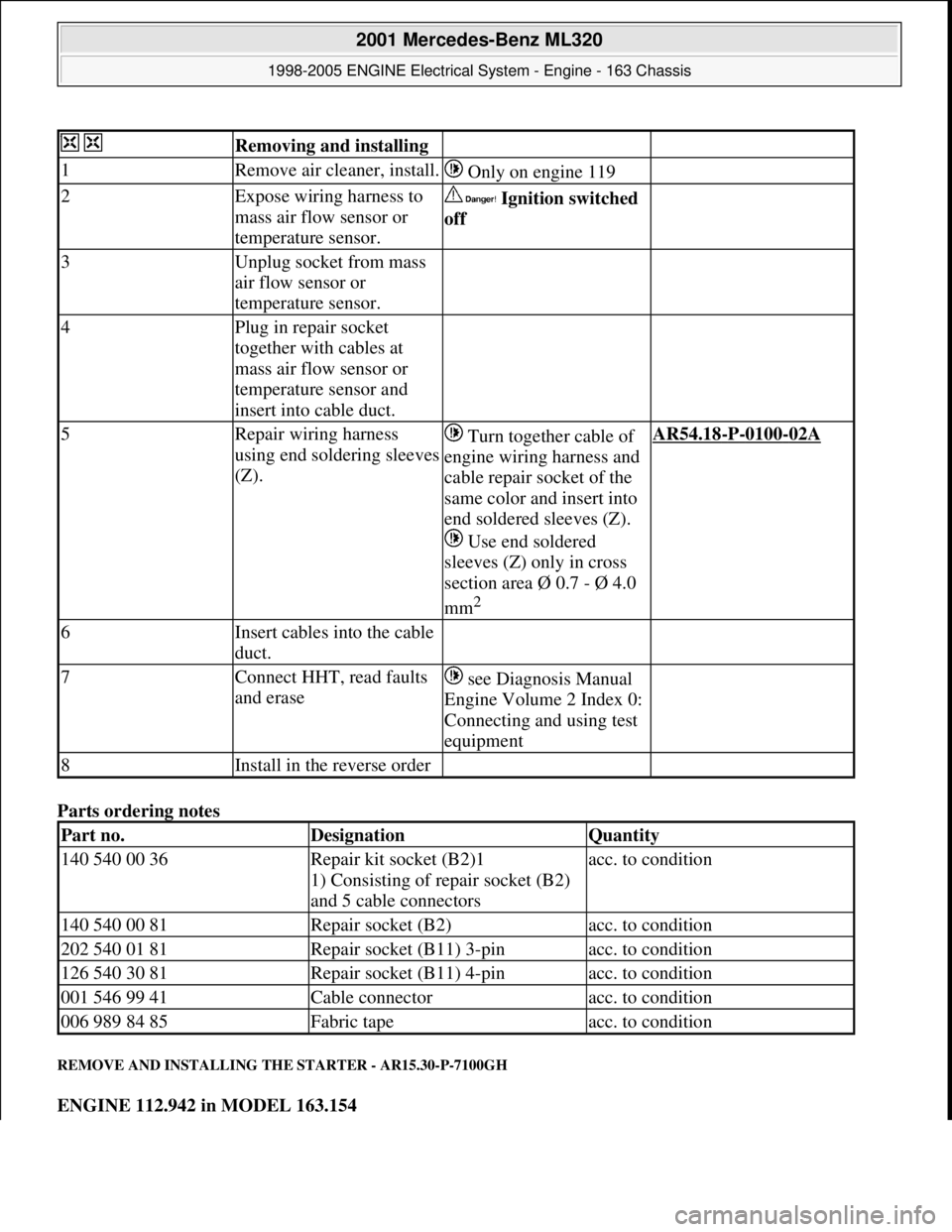
Parts ordering notes
REMOVE AND INSTALLING THE STARTER - AR15.30-P-7100GH
ENGINE 112.942 in MODEL 163.154
Removing and installing
1Remove air cleaner, install. Only on engine 119
2Expose wiring harness to
mass air flow sensor or
temperature sensor. Ignition switched
off
3Unplug socket from mass
air flow sensor or
temperature sensor.
4Plug in repair socket
together with cables at
mass air flow sensor or
temperature sensor and
insert into cable duct.
5Repair wiring harness
using end soldering sleeves
(Z). Turn together cable of
engine wiring harness and
cable repair socket of the
same color and insert into
end soldered sleeves (Z).
Use end soldered
sleeves (Z) only in cross
section area Ø 0.7 - Ø 4.0
mm
2
AR54.18-P-0100-02A
6Insert cables into the cable
duct.
7Connect HHT, read faults
and erase see Diagnosis Manual
Engine Volume 2 Index 0:
Connecting and using test
equipment
8Install in the reverse order
Part no.DesignationQuantity
140 540 00 36Repair kit socket (B2)1
1) Consisting of repair socket (B2)
and 5 cable connectorsacc. to condition
140 540 00 81Repair socket (B2)acc. to condition
202 540 01 81Repair socket (B11) 3-pinacc. to condition
126 540 30 81Repair socket (B11) 4-pinacc. to condition
001 546 99 41Cable connectoracc. to condition
006 989 84 85Fabric tapeacc. to condition
2001 Mercedes-Benz ML320
1998-2005 ENGINE Electrical System - Engine - 163 Chassis
me
Saturday, October 02, 2010 3:18:54 PMPage 49 © 2006 Mitchell Repair Information Company, LLC.
Page 2207 of 4133
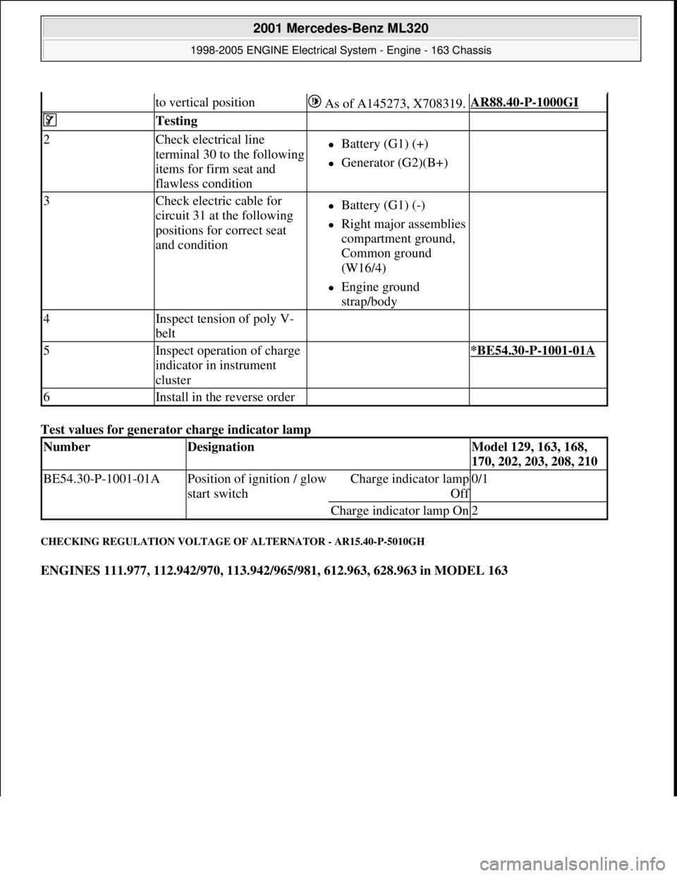
Test values for generator charge indicator lamp
CHECKING REGULATION VOLTAGE OF ALTERNATOR - AR15.40-P-5010GH
ENGINES 111.977, 112.942/970, 113.942/965/981, 612.963, 628.963 in MODEL 163
to vertical position As of A145273, X708319.AR88.40-P-1000GI
Testing
2Check electrical line
terminal 30 to the following
items for firm seat and
flawless conditionBattery (G1) (+)
Generator (G2)(B+)
3Check electric cable for
circuit 31 at the following
positions for correct seat
and conditionBattery (G1) (-)
Right major assemblies
compartment ground,
Common ground
(W16/4)
Engine ground
strap/body
4Inspect tension of poly V-
belt
5Inspect operation of charge
indicator in instrument
cluster *BE54.30-P-1001-01A
6Install in the reverse order
NumberDesignationModel 129, 163, 168,
170, 202, 203, 208, 210
BE54.30-P-1001-01APosition of ignition / glow
start switchCharge indicator lamp
Of
f
0/1
Charge indicator lamp On2
2001 Mercedes-Benz ML320
1998-2005 ENGINE Electrical System - Engine - 163 Chassis
me
Saturday, October 02, 2010 3:18:54 PMPage 53 © 2006 Mitchell Repair Information Company, LLC.