Page 1710 of 4133
Fig. 125: Identifying Radio And Navigation Unit Connector Assignments
VERSION CODING FOR RADIO AND NAVIGATION UNIT - AD82.61-P-2001-03A
The table below shows the possible navigation system adaptations to the vehicle. The settings can be changed
with the aid of the handheld tester ("HHT").
Navigation parametersPossible settings
ABS pulse count (pulse count
from wheel speed sensor per
wheel rotation)Factory setting:48 (passenger cars)
Tire sizee.g.:195/50/15
Tire condition Guideline values:
Coding is required only when
tires are changed. Tire wear
occurring while driving is
recognized automatically by the
navigation system.New:Tread depth greater than 5 mm
2001 Mercedes-Benz ML320
1998-2005 ACCESSORIES & BODY, CAB Electrical System - Body - 163 Chassis
me
Saturday, October 02, 2010 3:30:08 PMPage 215 © 2006 Mitchell Repair Information Company, LLC.
Page 1764 of 4133
Fig. 169: Identifying License Plate Lamp Components
REMOVING AND INSTALLING CENTER HIGH-MOUNTED STOP LAMP - AR82.10-P-5375GH
MODEL 163
Fig. 170: Identifying Center High
-Mounted Stop Lamp Components
Removal, installation
1Unscrew screws (1)
2Pry out license plate lamp
(E19/3, E19/4) with
suitable tool e.g. plastic wedge
3Reinstall in opposite
order Installation: Check
gasket (2) for license
plate lamp for condition
and proper seating.
4Check for proper function
Removal, installation
1Open tailgate
2Remove cover (1) for
center high-mounted stop
lamp(E21) Press cover in on right
and left (arrow A) until
catch hooks (2) are
2001 Mercedes-Benz ML320
1998-2005 ACCESSORIES & BODY, CAB Electrical System - Body - 163 Chassis
me
Saturday, October 02, 2010 3:30:09 PMPage 269 © 2006 Mitchell Repair Information Company, LLC.
Page 1780 of 4133
Fig. 188: Identifying Air Conditioning System Hose And Clip
Remove/Install
1Remove upper frame cross
member AR62.30-P-2300GH
2Drain the washer fluid
reservoir Manual pumpFig. 189
3Disconnect connectors
and hoses from pumps (5)Loosen wiring harness
from the side of the
washer fluid reservoir. If
fitted, disconnect plug
from washer fluid level
indicator switch.
4Unscrew bolt (2)
5Loosen air conditioning
hose (3) from clip (4)
6.1Remove covers and
locking clips from fuse
and relay module Only Model 163.128.
7Detach cooling module
(10) from lower grommets
8Remove washer fluid
reservoir (1) Loosen washer fluid
reservoir (1)from lower
grommets (6). Lift up
2001 Mercedes-Benz ML320
1998-2005 ACCESSORIES & BODY, CAB Electrical System - Body - 163 Chassis
me
Saturday, October 02, 2010 3:30:09 PMPage 285 © 2006 Mitchell Repair Information Company, LLC.
Page 1819 of 4133

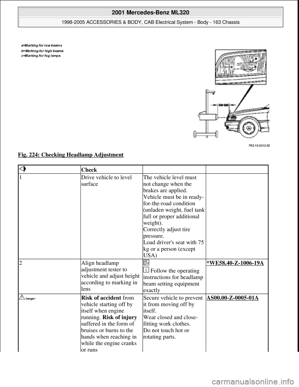
Fig. 224: Checking Headlamp Adjustment
Check
1Drive vehicle to level
surfaceThe vehicle level must
not change when the
brakes are applied.
Vehicle must be in ready-
for-the-road condition
(unladen weight, fuel tank
full or proper additional
weight).
Correctly adjust tire
pressure.
Load driver's seat with 75
kg or a person (except
USA)
2Align headlamp
adjustment tester to
vehicle and adjust height
according to marking in
lens
Follow the operating
instructions for headlamp
beam setting equipment
exactly*WE58.40-Z-1006-19A
Risk of accident from
vehicle starting off by
itself when engine
running. Risk of injury
suffered in the form of
bruises or burns to the
hands when reaching in
while the engine cranks
or runsSecure vehicle to prevent
it from moving off by
itself.
Wear closed and close-
fitting work clothes.
Do not touch hot or
rotating parts.AS00.00-Z-0005-01A
2001 Mercedes-Benz ML320
1998-2005 ACCESSORIES & BODY, CAB Electrical System - Body - 163 Chassis
me
Saturday, October 02, 2010 3:30:10 PMPage 324 © 2006 Mitchell Repair Information Company, LLC.
Page 1920 of 4133
Fig. 359: Identifying Telephone Console And Assembly Plate
3. Insert mount (1) into assembly plate (10) and install spiral cable into groove (arrow) of telephone console
(12) together with grommet.
Fig. 360: Identifying Mount, Assembly Plate And Telephone Console
4. Screw mount for console (14) to instrument panel with upper right mounting screw (arrow) of air
conditioning control module.
Holder for console (14) must be installed behind A/C control panel.
2001 Mercedes-Benz ML320
1998-2005 ACCESSORIES & BODY, CAB Electrical System - Body - 163 Chassis
me
Saturday, October 02, 2010 3:30:13 PMPage 425 © 2006 Mitchell Repair Information Company, LLC.
Page 1943 of 4133

Parts ordering notes
5Remove air conditioning
pushbutton control
module
6Remove overhead control
panel microphone flap
7Tie antenna lead Tied back in radio
shaft
Install
8Retrofit telephone cable
harness AZ82.70-P-0001-04G
9Retrofit hands-free
system microphone Mount in overhead
control panel.AZ82.70-P-0001-02GH
10Retrofitting telephone
console AZ82.70-P-0001-01G
11Install antenna on roof
See installation
instructions from the
Kathrein company.
12Check portable cellular
telephone for proper
function
13Complete vehicle
(following steps 6 to 1)
Part no.DesignationQuantity
B6 787 57 01Electro kit parts set (for D-net
only)1
B6 788 04 54Portable cellular telephone
console anthracite LHS1
B6 788 04 59Portable cellular telephone
console anthracite RHS1
B6 788 04 55Portable cellular telephone
console orion gray middle LHS1
B6 788 04 58Portable cellular telephone
console orion gray middle RHS1
B6 788 04 56Portable cellular telephone
console java LHS1
B6 788 04 57Portable cellular telephone
console java RHS1
B6 682 86 09Cover (with microphone), color
java
1
B6 682 86 10Cover (with microphone), color
light gray1
2001 Mercedes-Benz ML320
1998-2005 ACCESSORIES & BODY, CAB Electrical System - Body - 163 Chassis
me
Saturday, October 02, 2010 3:30:14 PMPage 448 © 2006 Mitchell Repair Information Company, LLC.
Page 1955 of 4133

gas. Risk of poisoning
and caustic burns from
swallowing battery
electrolyte. Risk of
injury from caustic burns
to eyes and skin from
battery electrolyte or
from handling damaged
lead-acid batteriesflames or smoking. Wear
acid-resistant gloves,
clothing and glasses. Pour
battery electrolyte only
into suitable and
appropriately marked
containers.
2Disconnect ground cable
of battery
AR54.10-P-0003A
Notes on batteryAll models.AH54.10-P-0001-01A
3Remove overhead control
panel
4Remove radio or
COMAND
5Remove stowage
compartment below radio
6Remove cover from radio
7Remove air conditioning
pushbutton control
module
Installation
8Retrofitting portable
cellular telephone mount
for hands-free system AZ82.70-P-0005-01GH
9Retrofitting hands-free
system wiring harness AZ82.70-P-0005-02GH
10Install D-net antenna on
roof See installation
instructions from the
Kathrein company.
Install antenna without
modification.
11Retrofit antenna lead Only on vehicles with
Audio 30 APS radioAZ82.70-P-0002-01A
12Retrofitting telephone
console Is fastened to center
console with mount (15)
and with screw (13).
13Reassemble vehicle 7-1
14Carry out start-up and
function testCheck telephone for
proper functioning
according to operating
instructions.
2001 Mercedes-Benz ML320
1998-2005 ACCESSORIES & BODY, CAB Electrical System - Body - 163 Chassis
me
Saturday, October 02, 2010 3:30:14 PMPage 460 © 2006 Mitchell Repair Information Company, LLC.
Page 1957 of 4133
Fig. 409: Identifying Portable CTEL Components
Removal
1Disconnect ground cable
of battery
AR54.10-P-0003A
2Remove radio or
COMAND
3Remove stowage
compartment below radio
4Remove cover from radio
5Remove air conditioning
pushbutton control
module
6Remove overhead control
panel
7Tie antenna lead Tied back in radio
shaft
Install
8Covering fiber optic
cable Do not kink or
stretch D2B fiber optic
cable.
Install caps on fiber
optic cable connector and
2001 Mercedes-Benz ML320
1998-2005 ACCESSORIES & BODY, CAB Electrical System - Body - 163 Chassis
me
Saturday, October 02, 2010 3:30:14 PMPage 462 © 2006 Mitchell Repair Information Company, LLC.