Page 3278 of 4133
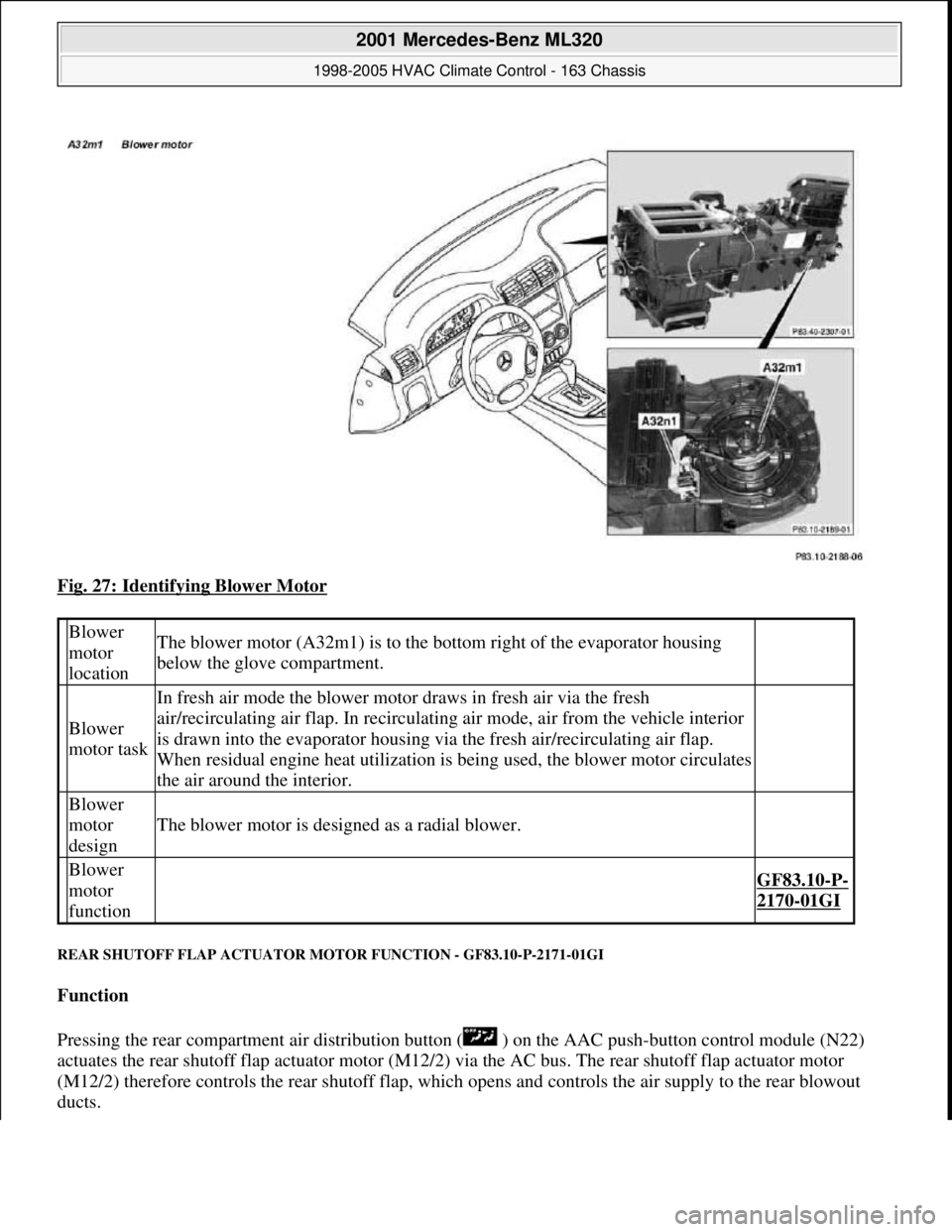
Fig. 27: Identifying Blower Motor
REAR SHUTOFF FLAP ACTUATOR MOTOR FUNCTION - GF83.10-P-2171-01GI
Function
Pressing the rear compartment air distribution button ( ) on the AAC push-button control module (N22)
actuates the rear shutoff flap actuator motor (M12/2) via the AC bus. The rear shutoff flap actuator motor
(M12/2) therefore controls the rear shutoff flap, which opens and controls the air supply to the rear blowout
ducts.
Blower
motor
locationThe blower motor (A32m1) is to the bottom right of the evaporator housing
below the glove compartment.
Blower
motor task
In fresh air mode the blower motor draws in fresh air via the fresh
air/recirculating air flap. In recirculating air mode, air from the vehicle interior
is drawn into the evaporator housing via the fresh air/recirculating air flap.
When residual engine heat utilization is being used, the blower motor circulates
the air around the interior.
Blower
motor
design
The blower motor is designed as a radial blower.
Blower
motor
function
GF83.10-P-
2170-01GI
2001 Mercedes-Benz ML320
1998-2005 HVAC Climate Control - 163 Chassis
me
Saturday, October 02, 2010 3:23:15 PMPage 34 © 2006 Mitchell Repair Information Company, LLC.
Page 3287 of 4133
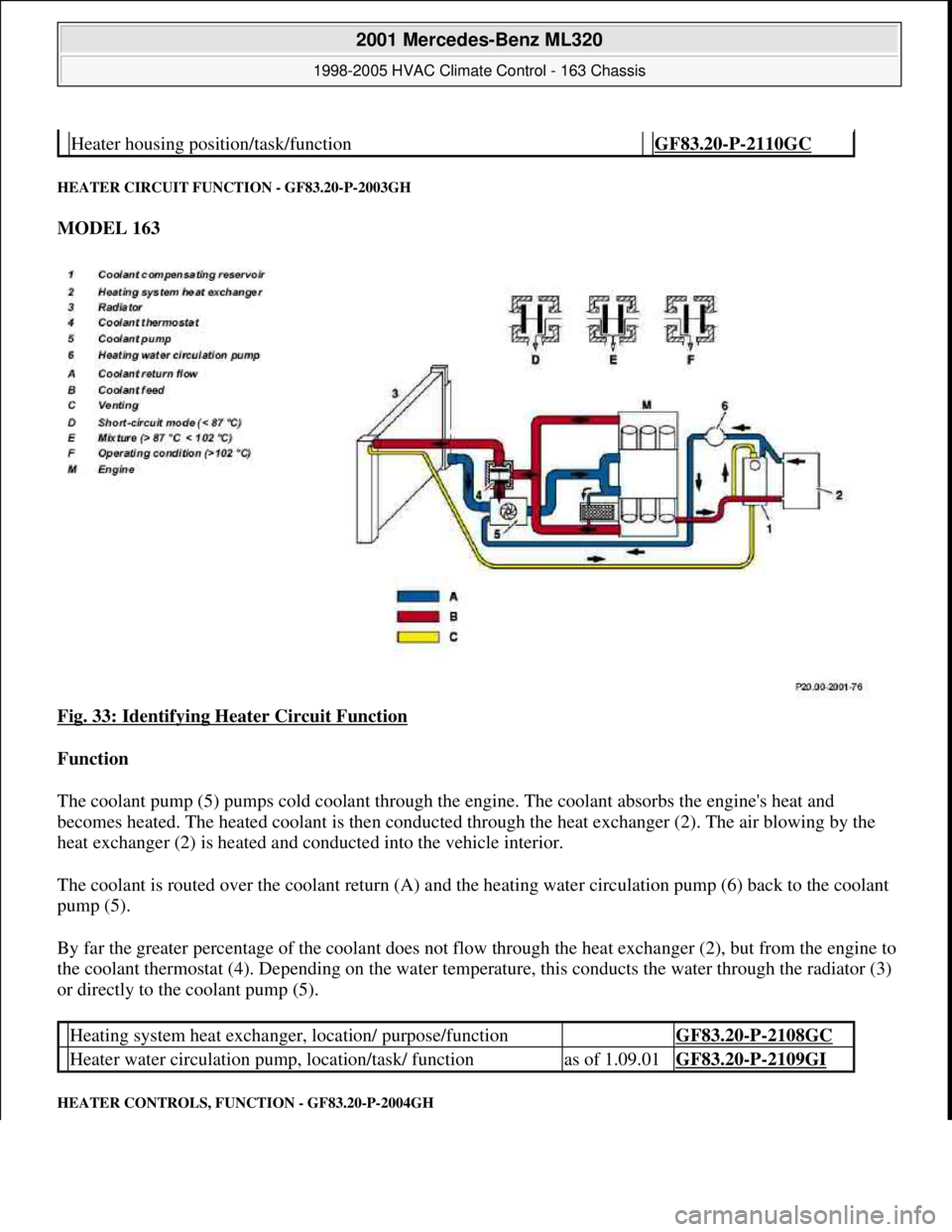
HEATER CIRCUIT FUNCTION - GF83.20-P-2003GH
MODEL 163
Fig. 33: Identifying Heater Circuit Function
Function
The coolant pump (5) pumps cold coolant through the engine. The coolant absorbs the engine's heat and
becomes heated. The heated coolant is then conducted through the heat exchanger (2). The air blowing by the
heat exchanger (2) is heated and conducted into the vehicle interior.
The coolant is routed over the coolant return (A) and the heating water circulation pump (6) back to the coolant
pump (5).
By far the greater percentage of the coolant does not flow through the heat exchanger (2), but from the engine to
the coolant thermostat (4). Depending on the water temperature, this conducts the water through the radiator (3)
or directly to the coolant pump (5).
HEATER CONTROLS, FUNCTION - GF83.20-P-2004GH
Heater housing position/task/function GF83.20-P-2110GC
Heating system heat exchanger, location/ purpose/function GF83.20-P-2108GC
Heater water circulation pump, location/task/ functionas of 1.09.01GF83.20-P-2109GI
2001 Mercedes-Benz ML320
1998-2005 HVAC Climate Control - 163 Chassis
me
Saturday, October 02, 2010 3:23:15 PMPage 43 © 2006 Mitchell Repair Information Company, LLC.
Page 3289 of 4133
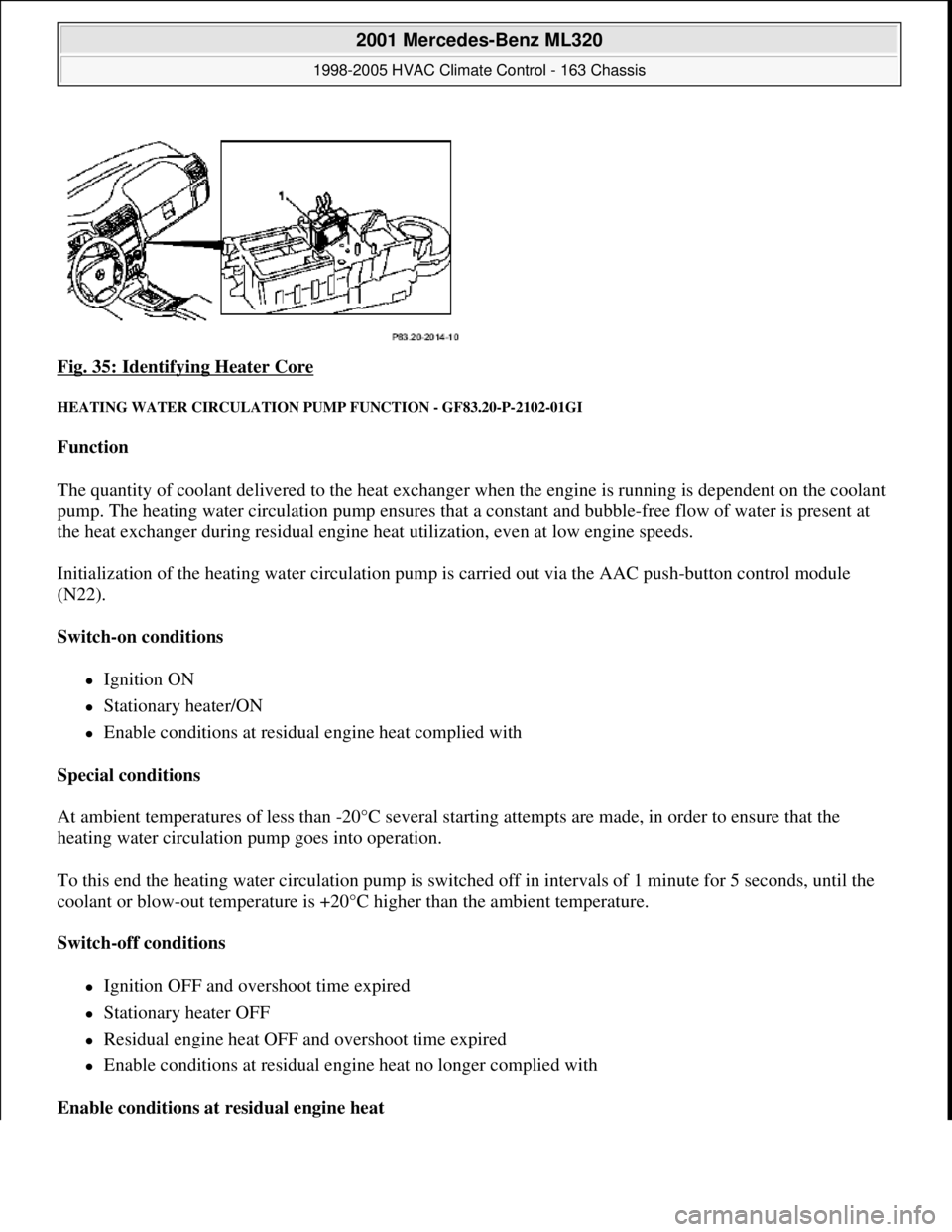
Fig. 35: Identifying Heater Core
HEATING WATER CIRCULATION PUMP FUNCTION - GF83.20-P-2102-01GI
Function
The quantity of coolant delivered to the heat exchanger when the engine is running is dependent on the coolant
pump. The heating water circulation pump ensures that a constant and bubble-free flow of water is present at
the heat exchanger during residual engine heat utilization, even at low engine speeds.
Initialization of the heating water circulation pump is carried out via the AAC push-button control module
(N22).
Switch-on conditions
Ignition ON
Stationary heater/ON
Enable conditions at residual engine heat complied with
Special conditions
At ambient temperatures of less than -20°C several starting attempts are made, in order to ensure that the
heating water circulation pump goes into operation.
To this end the heating water circulation pump is switched off in intervals of 1 minute for 5 seconds, until the
coolant or blow-out temperature is +20°C higher than the ambient temperature.
Switch-off conditions
Ignition OFF and overshoot time expired
Stationary heater OFF
Residual engine heat OFF and overshoot time expired
Enable conditions at residual engine heat no longer complied with
Enable conditions at residual engine heat
2001 Mercedes-Benz ML320
1998-2005 HVAC Climate Control - 163 Chassis
me
Saturday, October 02, 2010 3:23:15 PMPage 45 © 2006 Mitchell Repair Information Company, LLC.
Page 3290 of 4133
The heating water circulation pump runs in any event 1 minute after starting residual engine heat operation. The
overshoot conditions at least will be fulfilled.
Overshoot conditions
Coolant temperature 100°C --> overshoot time 5 minutes
Coolant temperature >100°C --> overshoot time 10 minutes
HEATER HOUSING POSITION - GF83.20-P-2103-01GH
The heater housing (1) is located beneath the instrument panel.
Fig. 36: Identifying Heater Housing
HEATER BOX FUNCTION - GF83.20-P-2103-02GH
Operating condition: Heating
2001 Mercedes-Benz ML320
1998-2005 HVAC Climate Control - 163 Chassis
me
Saturday, October 02, 2010 3:23:15 PMPage 46 © 2006 Mitchell Repair Information Company, LLC.
Page 3293 of 4133
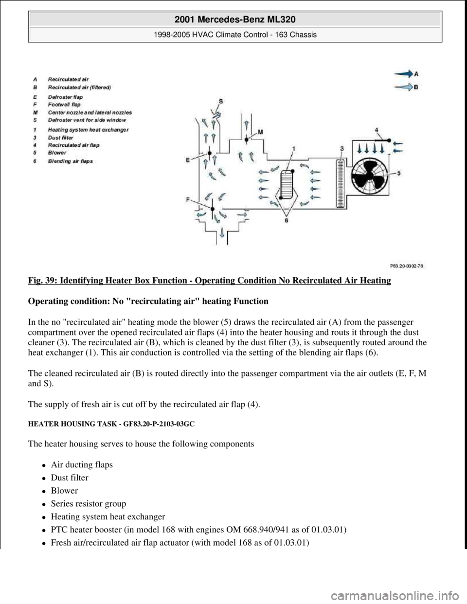
Fig. 39: Identifying Heater Box Function - Operating Condition No Recirculated Air Heating
Operating condition: No "recirculating air" heating Function
In the no "recirculated air" heating mode the blower (5) draws the recirculated air (A) from the passenger
compartment over the opened recirculated air flaps (4) into the heater housing and routs it through the dust
cleaner (3). The recirculated air (B), which is cleaned by the dust filter (3), is subsequently routed around the
heat exchanger (1). This air conduction is controlled via the setting of the blending air flaps (6).
The cleaned recirculated air (B) is routed directly into the passenger compartment via the air outlets (E, F, M
and S).
The supply of fresh air is cut off by the recirculated air flap (4).
HEATER HOUSING TASK - GF83.20-P-2103-03GC
The heater housing serves to house the following components
Air ducting flaps
Dust filter
Blower
Series resistor group
Heating system heat exchanger
PTC heater booster (in model 168 with engines OM 668.940/941 as of 01.03.01)
Fresh air/recirculated air flap actuator (with model 168 as of 01.03.01)
2001 Mercedes-Benz ML320
1998-2005 HVAC Climate Control - 163 Chassis
me
Saturday, October 02, 2010 3:23:15 PMPage 49 © 2006 Mitchell Repair Information Company, LLC.
Page 3295 of 4133
The fresh air/recirculated air flap shuts off the supply of recirculated air.
Fresh air is drawn in.
Recirculation mode
The fresh air/recirculated air flap shuts off the supply of fresh air. Air is drawn in from the passenger
compartment.
HEATER CORE, LOCATION/PURPOSE/FUNCTION - GF83.20-P-2108GC
MODEL 163, 168
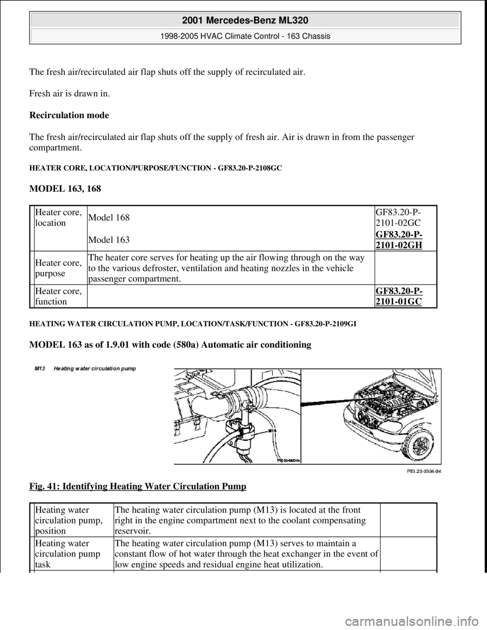
HEATING WATER CIRCULATION PUMP, LOCATION/TASK/FUNCTION - GF83.20-P-2109GI
MODEL 163 as of 1.9.01 with code (580a) Automatic air conditioning
Fig. 41: Identifying Heating Water Circulation Pump
Heater core,
locationModel 168GF83.20-P-
2101-02GC
Model 163GF83.20-P-
2101-02GH
Heater core,
purposeThe heater core serves for heating up the air flowing through on the way
to the various defroster, ventilation and heating nozzles in the vehicle
passenger compartment.
Heater core,
function GF83.20-P-
2101-01GC
Heating water
circulation pump,
positionThe heating water circulation pump (M13) is located at the front
right in the engine compartment next to the coolant compensating
reservoir.
Heating water
circulation pump
taskThe heating water circulation pump (M13) serves to maintain a
constant flow of hot water through the heat exchanger in the event of
low engine speeds and residual engine heat utilization.
2001 Mercedes-Benz ML320
1998-2005 HVAC Climate Control - 163 Chassis
me
Saturday, October 02, 2010 3:23:15 PMPage 51 © 2006 Mitchell Repair Information Company, LLC.
Page 3304 of 4133
After starting, the refrigerant compressor starts up. If cooling is not necessary, the refrigerant compressor's
output is lowered and switched off via the icing inhibitor.
The air conditioning is always ready for operation after the engine has been started, and operates according to
the so-called "reheat" principle. This means: The refrigerant compressor always operates at an ambient
temperature in excess of 1°C, therefore also cools cold incoming air. Following the cooling process, the dried
air is heated at the heat exchanger.
On the one hand, this effect serves the purpose of comfort, because cooling also simultaneously causes air
dehumidification which, in turn, is an important prerequisite for a pleasant interior climate. On the other hand,
the air is dried as a result of this cooling and heating, thereby preventing window fogging.
Pressing the AC button again ( ) (does not illuminate) switches off the cooling.
Heating mode
The in-car temperature sensor measures the air temperature in the interior of the vehicle.
The air conditioning control module electronics compares the in-car temperature with the desired temperature
which has been set at the temperature selector wheels.
The microprocessor adjusts the air conditioning electronics or keeps the relevant setting constant as required.
Heater operation with heater booster in vehicles with engine 612.963 as of 12/99
In vehicles equipped with direct-injection diesel engines, an electrical heater booster is additionally installed in
the evaporator housing downstream of the heat exchanger, in order to compensate any heater output deficit
which exists under certain operating conditions.
The 3 heating elements in the heater booster are supplied with current, whereupon they are heated and they start
to glow. As a result of the structural conditions, it is ensured that the drawn in fresh air flows directly past the
electric heater booster, and is therefore heated.
Cooling mode
The icing inhibitor measures the temperature at the evaporator air outlet, while the interior temperature sensor
determines the relevant in-car temperature.
The air conditioning control module electronics compares the various measured values with the desired
temperature which has been set at the temperature selector wheels.
The microprocessor adjusts the air conditioning or keeps the relevant setting constant as required.
In-car temperature sensor replaced by new typeas of 1.12.99BT83.57-P-0001-04GH
Ventilation, function GF83.10-P-2000GH
Heater circuit function GF83.20-P-2003GH
2001 Mercedes-Benz ML320
1998-2005 HVAC Climate Control - 163 Chassis
me
Saturday, October 02, 2010 3:23:15 PMPage 60 © 2006 Mitchell Repair Information Company, LLC.
Page 3305 of 4133
AIR CONDITIONING, LOCATION OF COMPONENTS - GF83.30-P-0003-01GH
Location of components in passenger compartment
Fig. 50: Identifying Air Conditioning Components In Passenger Compartment (1 Of 2)
Location of components in passenger compartment
Air conditioning control module function GF83.30-P-2001GH
Refrigerant circuit function GF83.40-P-2001GH
Temperature control, function GF83.57-P-2000GH
Heater booster (ZUH), function Engine 612.963GF83.70-P-0005GH
2001 Mercedes-Benz ML320
1998-2005 HVAC Climate Control - 163 Chassis
me
Saturday, October 02, 2010 3:23:15 PMPage 61 © 2006 Mitchell Repair Information Company, LLC.