1997 MERCEDES-BENZ ML320 engine
[x] Cancel search: enginePage 3199 of 4133
AR88.40-P-3060GH
Remove/install engine hood hinge
16.4.97
MODEL
163.113 /128 /136 /154 /157 /172 /174 /175
P88.40-0365-01
P88.40-0364-01
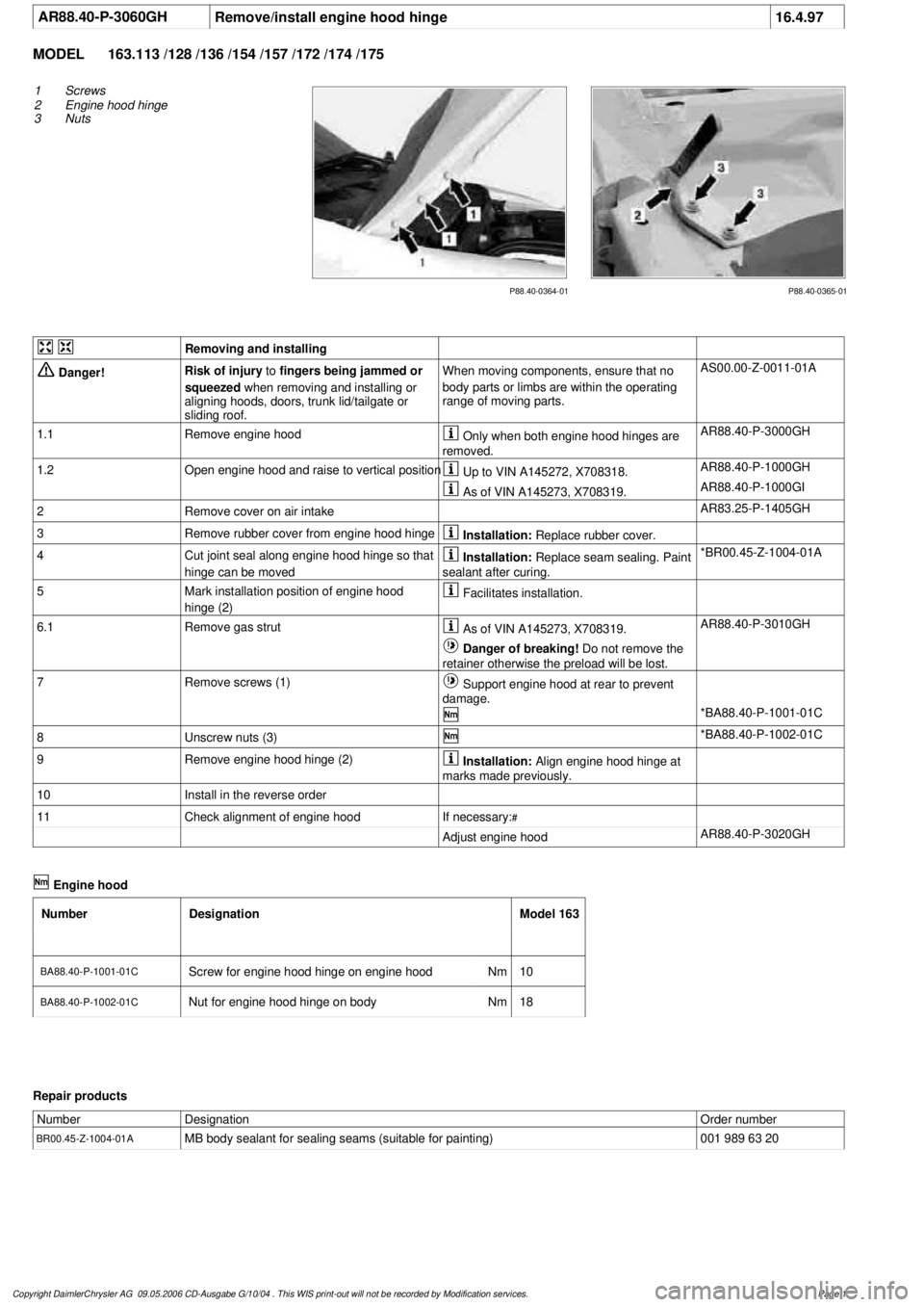
1
Screws
2
Engine hood hinge
3
Nuts
Removing and installing
Danger!
Risk of injury
to
fingers being jammed or
squeezed
when removing and installing or
aligning hoods, doors, trunk lid/tailgate or
sliding roof.
When moving components, ensure that no
body parts or limbs are within the operating
range of moving parts.
AS00.00-Z-0011-01A
1.1
Remove engine hood
Only when both engine hood hinges are
removed.
AR88.40-P-3000GH
1.2
Open engine hood and raise to vertical position
Up to VIN A145272, X708318.
AR88.40-P-1000GH
As of VIN A145273, X708319.
AR88.40-P-1000GI
2
Remove cover on air intake
AR83.25-P-1405GH
3
Remove rubber cover from engine hood hinge
Installation:
Replace rubber cover.
4
Cut joint seal along engine hood hinge so that
hinge can be moved
Installation:
Replace seam sealing. Paint
sealant after curing.
*BR00.45-Z-1004-01A
5
Mark installation position of engine hood
hinge (2)
Facilitates installation.
6.1
Remove gas strut
As of VIN A145273, X708319.
AR88.40-P-3010GH
Danger of breaking!
Do not remove the
retainer otherwise the preload will be lost.
7
Remove screws (1)
Support engine hood at rear to prevent
damage.
*BA88.40-P-1001-01C
8
Unscrew nuts (3)
*BA88.40-P-1002-01C
9
Remove engine hood hinge (2)
Installation:
Align engine hood hinge at
marks made previously.
10
Install in the reverse order
11
Check alignment of engine hood
If necessary:
#
Adjust engine hood
AR88.40-P-3020GH
Engine hood
Number
Designation
Model 163
BA88.40-P-1001-01C
Screw for engine hood hinge on engine hood
Nm
10
BA88.40-P-1002-01C
Nut for engine hood hinge on body
Nm
18
Repair products
Number
Designation
Order number
BR00.45-Z-1004-01A
MB body sealant for sealing seams (suitable for painting)
001 989 63 20
Copyright DaimlerChrysler AG 09.05.2006 CD-Ausgabe G/10/04 . This WIS print-out will not be recorde
d by Modification services.
Page 1
Page 3200 of 4133
SM63.20-P-0002GH
Reinforce engine hood hinge support on front left
16.1.02
MODELS
163.136 /154 /172 #A as of 145273,
163.136 /154 /172 #X as of 708319,
163.113 /128 /174 /175
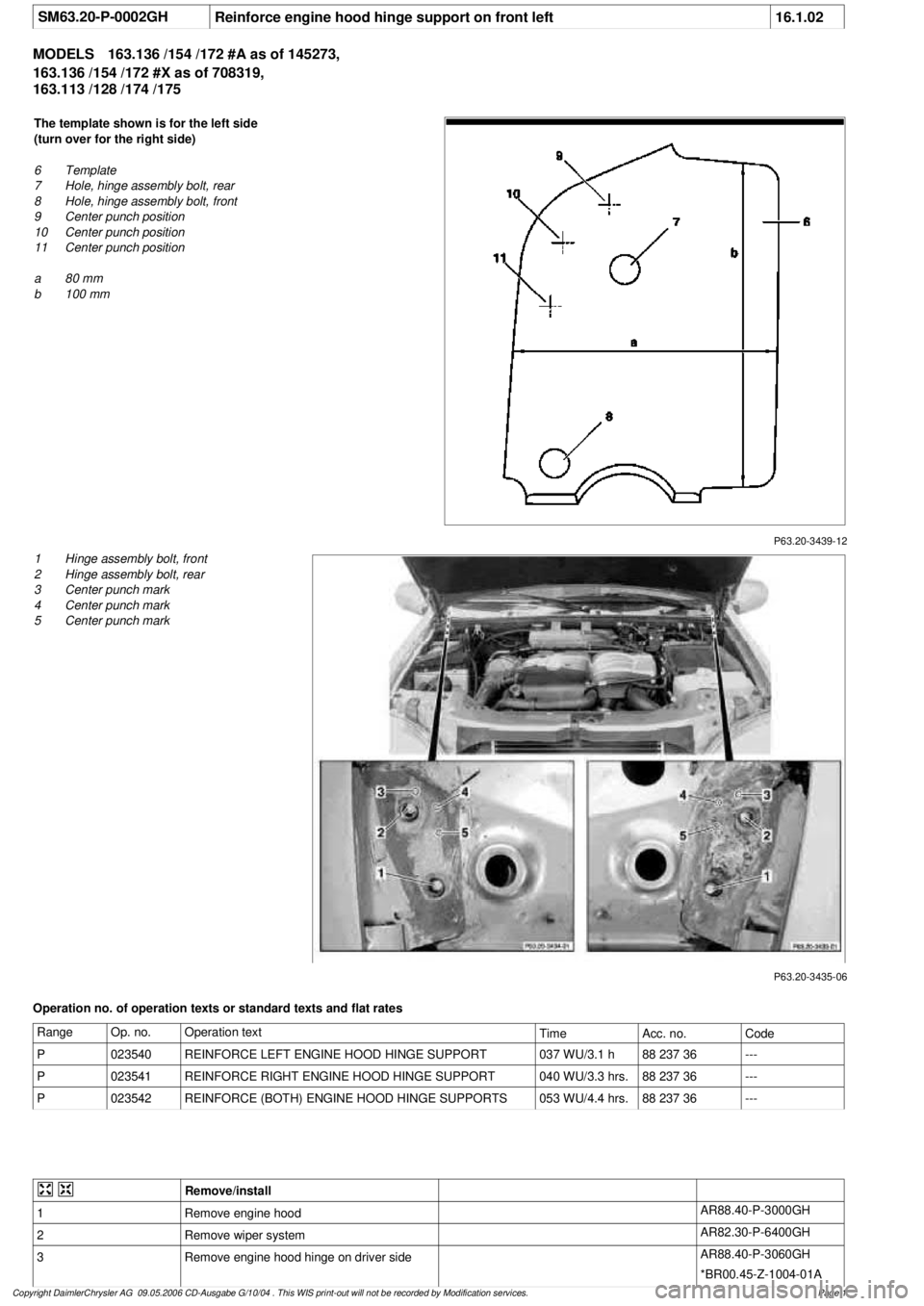
P63.20-3439-12
The template shown is for the left side
(turn over for the right side)
6
Template
7
Hole, hinge assembly bolt, rear
8
Hole, hinge assembly bolt, front
9
Center punch position
10
Center punch position
11
Center punch position
a
80 mm
b
100 mm
P63.20-3435-06
1
Hinge assembly bolt, front
2
Hinge assembly bolt, rear
3
Center punch mark
4
Center punch mark
5
Center punch mark
Operation no. of operation texts or standard texts and flat rates
Range
Op. no.
Operation text
Time
Acc. no.
Code
P
023540
REINFORCE LEFT ENGINE HOOD HINGE SUPPORT
037 WU/3.1 h
88 237 36
---
P
023541
REINFORCE RIGHT ENGINE HOOD HINGE SUPPORT
040 WU/3.3 hrs.
88 237 36
---
P
023542
REINFORCE (BOTH) ENGINE HOOD HINGE SUPPORTS
053 WU/4.4 hrs.
88 237 36
---
Remove/install
1
Remove engine hood
AR88.40-P-3000GH
2
Remove wiper system
AR82.30-P-6400GH
3
Remove engine hood hinge on driver side
AR88.40-P-3060GH
*BR00.45-Z-1004-01A
Copyright DaimlerChrysler AG 09.05.2006 CD-Ausgabe G/10/04 . This WIS print-out will not be recorde
d by Modification services.
Page 1
Page 3201 of 4133
Danger!
Risk of explosion
from explosive gas.
Risk
of poisoning and caustic burns from
swallowing battery electrolyte.
Risk of injury
through burns to skin and eyes from battery
acid or when handling damaged lead-acid
batteries
No fire, sparks, naked flames or smoking.
Wear protective gloves, acid-resistant
clothing and safety glasses. Pour battery
electrolyte only into suitable and appropriately
marked containers.
AS54.10-Z-0001-01A
4
Remove battery
AR54.10-P-0005GH
5
Press out template (6) and adapt the size to
the correct dimensions (a, b)Determine ACTUAL dimension (a) from the
drawing.
Divide the SPECIFIED dimension (a) by the
determined ACTUAL dimension (a) and copy
the template to the original size with the
corresponding factor.
Check dimensions for both axles.
6
Cut out template
7
Cut out holes (7, 8) for engine hood hinge
studs
8
Position template in the engine hood hinge
support using the stud holes
The template is drawn for the left side.
Turn over to obtain the right side.
9
Center the engine hood hinge support on the
template using the markings (9, 10, 11)
10
Remove template
11
Drill a hole at each center punch mark (3, 4, 5)
Only drill through the 2 upper panels. Do
not drill through the reinforcement panel (3rd
panel).
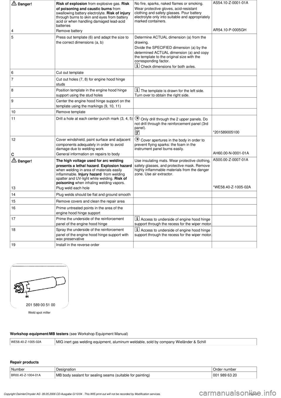
*201589005100
12
Cover windshield, paint surface and adjacent
components adequately in order to avoid
damage due to welding work
Cover apertures in the body in order to
prevent flying sparks: the foam in the
instrument panel burns easily.
c
General information on repairs to body
AH60.00-N-0001-01A
Danger!
The high voltage used for arc welding
presents a lethal hazard
.
Explosion hazard
when welding in area of materials easily
inflammable.
Injury hazard
from welding
spatter and UV-light while welding.
Risk of
poisoning
when inhaling welding vapors.
Use insulating mats. Wear protective clothing,
safety glasses, and protective mask.
Remove
highly inflammable materials from the danger
zone. Use air extractor.
AS00.00-Z-0007-01A
13
Plug weld each hole
*WE58.40-Z-1005-02A
14
Plug welds should be flat and ground smooth
15
Remove covers and clean the repair area
16
Prime untreated points in the area of the
engine hood hinge support
17
Prime the underside of the reinforcement
panel of the engine hood hinge
Access to underside of engine hood hinge
support through the recess for the wiper motor.
18
Spray the underside of the reinforcement
panel of the engine hood hinge support with
wax preservative
Access to underside of engine hood hinge
support through the recess for the wiper motor.
19
Install in the reverse order
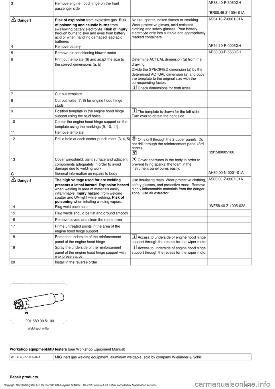
Weld spot miller
201 589 00 51 00
Workshop equipment/MB testers
(see Workshop Equipment Manual)
WE58.40-Z-1005-02A
MIG inert gas welding equipment, aluminum weldable, sold by company Wieländer & Schill
Repair products
Number
Designation
Order number
BR00.45-Z-1004-01A
MB body sealant for sealing seams (suitable for painting)
001 989 63 20
Copyright DaimlerChrysler AG 09.05.2006 CD-Ausgabe G/10/04 . This WIS print-out will not be recorde
d by Modification services.
Page 2
Page 3203 of 4133
SM63.20-P-0003GI
Reinforce right front engine hood hinge support
16.1.02
MODELS
163.136 /154 /172 #A as of 145273,
163.136 /154 /172 #X as of 708319,
163.113 /128 /174 /175
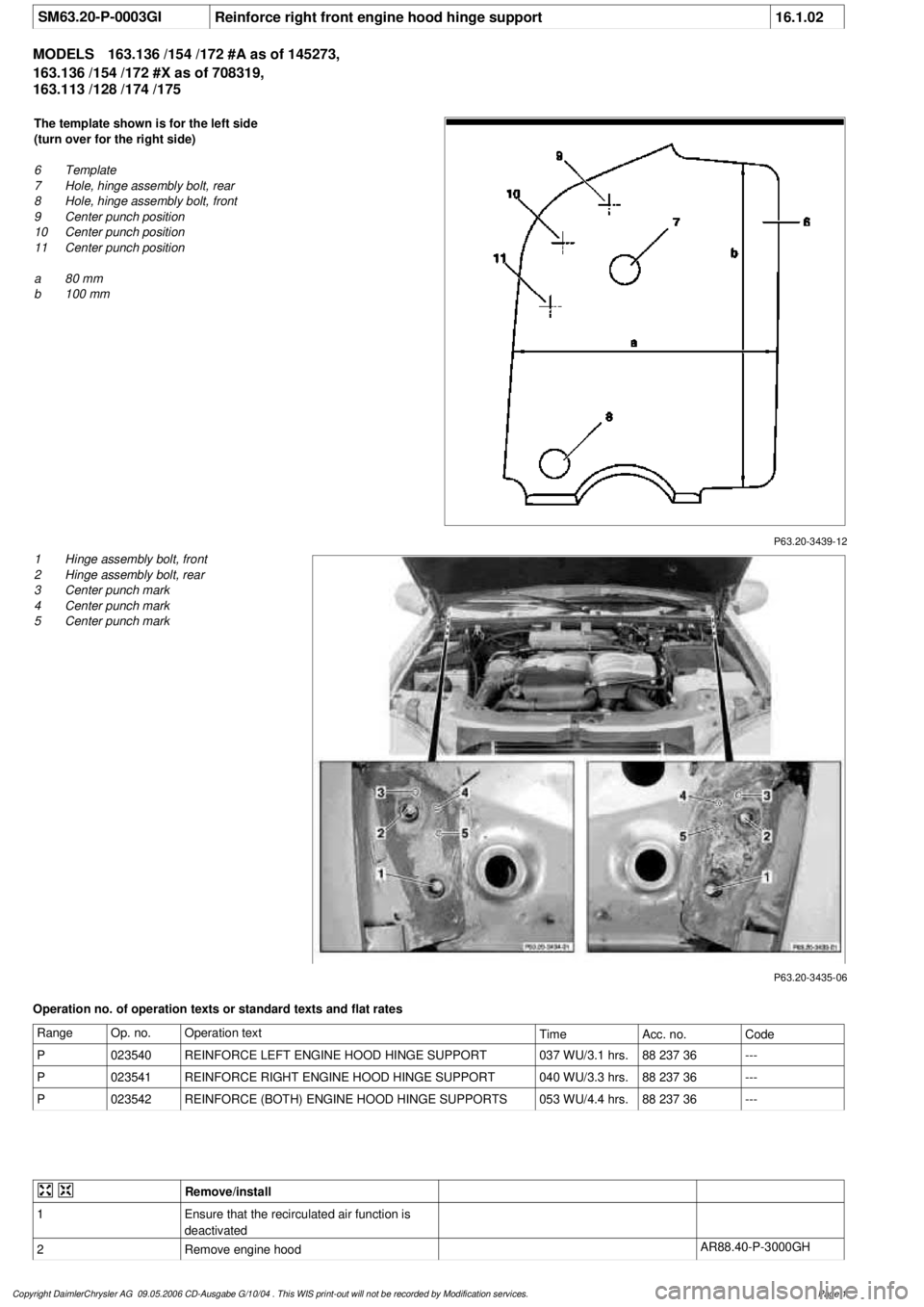
P63.20-3439-12
The template shown is for the left side
(turn over for the right side)
6
Template
7
Hole, hinge assembly bolt, rear
8
Hole, hinge assembly bolt, front
9
Center punch position
10
Center punch position
11
Center punch position
a
80 mm
b
100 mm
P63.20-3435-06
1
Hinge assembly bolt, front
2
Hinge assembly bolt, rear
3
Center punch mark
4
Center punch mark
5
Center punch mark
Operation no. of operation texts or standard texts and flat rates
Range
Op. no.
Operation text
Time
Acc. no.
Code
P
023540
REINFORCE LEFT ENGINE HOOD HINGE SUPPORT
037 WU/3.1 hrs.
88 237 36
---
P
023541
REINFORCE RIGHT ENGINE HOOD HINGE SUPPORT
040 WU/3.3 hrs.
88 237 36
---
P
023542
REINFORCE (BOTH) ENGINE HOOD HINGE SUPPORTS
053 WU/4.4 hrs.
88 237 36
---
Remove/install
1
Ensure that the recirculated air function is
deactivated
2
Remove engine hood
AR88.40-P-3000GH
Copyright DaimlerChrysler AG 09.05.2006 CD-Ausgabe G/10/04 . This WIS print-out will not be recorde
d by Modification services.
Page 1
Page 3204 of 4133
3
Remove engine hood hinge on the front
passenger side
AR88.40-P-3060GH
*BR00.45-Z-1004-01A
Danger!
Risk of explosion
from explosive gas.
Risk
of poisoning and caustic burns from
swallowing battery electrolyte.
Risk of injury
through burns to skin and eyes from battery
acid or when handling damaged lead-acid
batteries
No fire, sparks, naked flames or smoking.
Wear protective gloves, acid-resistant
clothing and safety glasses. Pour battery
electrolyte only into suitable and appropriately
marked containers.
AS54.10-Z-0001-01A
4
Remove battery
AR54.10-P-0005GH
5
Remove air conditioning blower motor
AR83.30-P-5560GH
6
Print out template (6) and adapt the size to
the correct dimensions (a, b)Determine ACTUAL dimension (a) from the
drawing.
Divide the SPECIFIED dimension (a) by the
determined ACTUAL dimension (a) and copy
the template to the original size with the
corresponding factor.
Check dimensions for both axles.
7
Cut out template
8
Cut out holes (7, 8) for engine hood hinge
studs
9
Position template in the engine hood hinge
support using the stud holes
The template is drawn for the left side.
Turn over to obtain the right side.
10
Center the engine hood hinge support on the
template using the markings (9, 10, 11)
11
Remove template
12
Drill a hole at each center punch mark (3, 4, 5)
Only drill through the 2 upper panels. Do
not drill through the reinforcement panel (3rd
panel).
*201589005100
13
Cover windshield, paint surface and adjacent
components adequately in order to avoid
damage due to welding work
Cover apertures in the body in order to
prevent flying sparks: the foam in the
instrument panel burns easily.
c
General information on repairs to body
AH60.00-N-0001-01A
Danger!
The high voltage used for arc welding
presents a lethal hazard
.
Explosion hazard
when welding in area of materials easily
inflammable.
Injury hazard
from welding
spatter and UV-light while welding.
Risk of
poisoning
when inhaling welding vapors.
Use insulating mats. Wear protective clothing,
safety glasses, and protective mask.
Remove
highly inflammable materials from the danger
zone. Use air extractor.
AS00.00-Z-0007-01A
14
Plug weld each hole
*WE58.40-Z-1005-02A
15
Plug welds should be flat and ground smooth
16
Remove covers and clean the repair area
17
Prime untreated points in the area of the
engine hood hinge support
18
Prime the underside of the reinforcement
panel of the engine hood hinge
Access to underside of engine hood hinge
support through the recess for the wiper motor.
19
Spray the underside of the reinforcement
panel of the engine hood hinge support with
wax preservative
Access to underside of engine hood hinge
support through the recess for the wiper motor.
20
Install in the reverse order
Weld spot miller
201 589 00 51 00
Workshop equipment/MB testers
(see Workshop Equipment Manual)
WE58.40-Z-1005-02A
MIG inert gas welding equipment, aluminum weldable, sold by company Wieländer & Schill
Repair products
Copyright DaimlerChrysler AG 09.05.2006 CD-Ausgabe G/10/04 . This WIS print-out will not be recorde
d by Modification services.
Page 2
Page 3206 of 4133
AR88.40-P-3200GI
Remove/install engine hood lock
9.4.99
MODEL
163.136 /154 /172 #A as of 145273,
163.136 /154 /172 #X as of 708319,
163.113 /128 /157 /174 /175
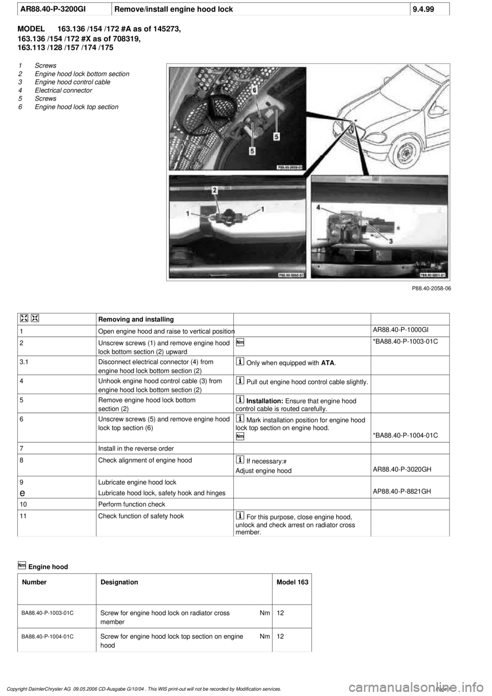
P88.40-2058-06
1
Screws
2
Engine hood lock bottom section
3
Engine hood control cable
4
Electrical connector
5
Screws
6
Engine hood lock top section
Removing and installing
1
Open engine hood and raise to vertical position
AR88.40-P-1000GI
2
Unscrew screws (1) and remove engine hood
lock bottom section (2) upward
*BA88.40-P-1003-01C
3.1
Disconnect electrical connector (4) from
engine hood lock bottom section (2)
Only when equipped with
ATA
.
4
Unhook engine hood control cable (3) from
engine hood lock bottom section (2)
Pull out engine hood control cable slightly.
5
Remove engine hood lock bottom
section (2)
Installation:
Ensure that engine hood
control cable is routed carefully.
6
Unscrew screws (5) and remove engine hood
lock top section (6)
Mark installation position for engine hood
lock top section on engine hood.
*BA88.40-P-1004-01C
7
Install in the reverse order
8
Check alignment of engine hood
If necessary:
#
Adjust engine hood
AR88.40-P-3020GH
9
Lubricate engine hood lock
e
Lubricate hood lock, safety hook and hinges
AP88.40-P-8821GH
10
Perform function check
11
Check function of safety hook
For this purpose, close engine hood,
unlock and check arrest on radiator cross
member.
Engine hood
Number
Designation
Model 163
BA88.40-P-1003-01C
Screw for engine hood lock on radiator cross
member
Nm
12
BA88.40-P-1004-01C
Screw for engine hood lock top section on engine
hood
Nm
12
Copyright DaimlerChrysler AG 09.05.2006 CD-Ausgabe G/10/04 . This WIS print-out will not be recorde
d by Modification services.
Page 1
Page 3207 of 4133
AP88.40-P-8821GH
Lubricating hood catch, locking hook and hinges
2.7.97
MODEL
163
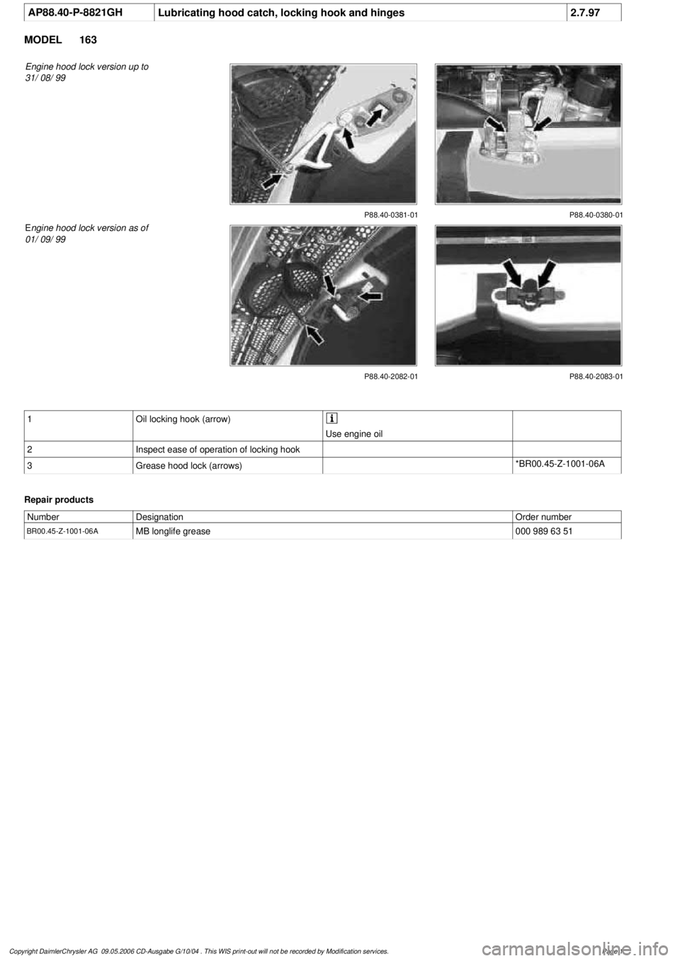
Engine hood lock version up to
31/ 08/ 99
P88.40-0381-01 P88.40-0380-01
P88.40-2082-01
E
ngine hood lock version as of
01/ 09/ 99
P88.40-2083-01
1
Oil locking hook (arrow)
Use engine oil
2
Inspect ease of operation of locking hook
3
Grease hood lock (arrows)
*BR00.45-Z-1001-06A
Repair products
Number
Designation
Order number
BR00.45-Z-1001-06A
MB longlife grease
000 989 63 51
Copyright DaimlerChrysler AG 09.05.2006 CD-Ausgabe G/10/04 . This WIS print-out will not be recorde
d by Modification services.
Page 1
Page 3208 of 4133
AR88.40-P-3200GH
Removing and installing engine hood lock
8.4.99
MODEL
163.136 /154 /172 up to 31.8.99
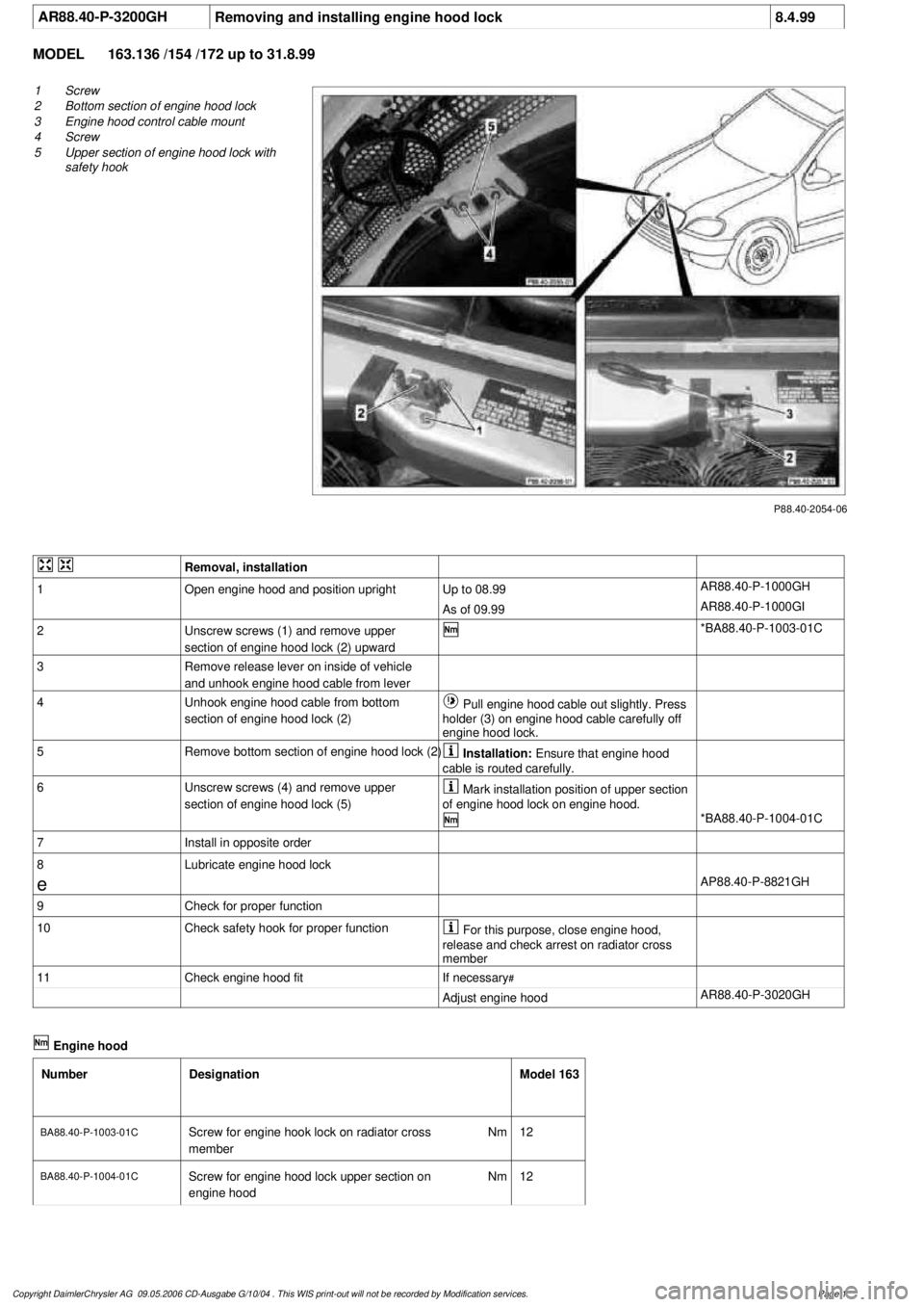
P88.40-2054-06
1
Screw
2
Bottom section of engine hood lock
3
Engine hood control cable mount
4
Screw
5
Upper section of engine hood lock with
safety hook
Removal, installation
1
Open engine hood and position upright
Up to 08.99
AR88.40-P-1000GH
As of 09.99
AR88.40-P-1000GI
2
Unscrew screws (1) and remove upper
section of engine hood lock (2) upward
*BA88.40-P-1003-01C
3
Remove release lever on inside of vehicle
and unhook engine hood cable from lever
4
Unhook engine hood cable from bottom
section of engine hood lock (2)
Pull engine hood cable out slightly. Press
holder (3) on engine hood cable carefully off
engine hood lock.
5
Remove bottom section of engine hood lock (2)
Installation:
Ensure that engine hood
cable is routed carefully.
6
Unscrew screws (4) and remove upper
section of engine hood lock (5)
Mark installation position of upper section
of engine hood lock on engine hood.
*BA88.40-P-1004-01C
7
Install in opposite order
8
Lubricate engine hood lock
e
AP88.40-P-8821GH
9
Check for proper function
10
Check safety hook for proper function
For this purpose, close engine hood,
release and check arrest on radiator cross
member
11
Check engine hood fit
If necessary
#
Adjust engine hood
AR88.40-P-3020GH
Engine hood
Number
Designation
Model 163
BA88.40-P-1003-01C
Screw for engine hook lock on radiator cross
member
Nm
12
BA88.40-P-1004-01C
Screw for engine hood lock upper section on
engine hood
Nm
12
Copyright DaimlerChrysler AG 09.05.2006 CD-Ausgabe G/10/04 . This WIS print-out will not be recorde
d by Modification services.
Page 1