1997 MERCEDES-BENZ ML320 engine
[x] Cancel search: enginePage 3339 of 4133
Blending air flap actuator
Fresh air/recirculated air flap actuator
Defroster vent flap actuator motor
Rear shutoff flap actuator motor
Footwell flap actuator
Electric heater booster (for engine 612.963 only) and therefore forms a complete unit.
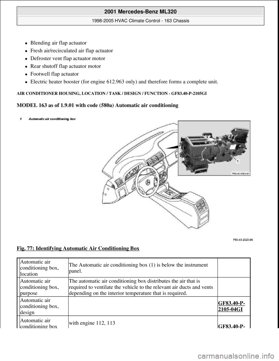
AIR CONDITIONER HOUSING, LOCATION / TASK / DESIGN / FUNCTION - GF83.40-P-2105GI
MODEL 163 as of 1.9.01 with code (580a) Automatic air conditioning
Fig. 77: Identifying Automatic Air Conditioning Box
Automatic air
conditioning box,
locationThe Automatic air conditioning box (1) is below the instrument
panel.
Automatic air
conditioning box,
purposeThe automatic air conditioning box distributes the air that is
required to ventilate the vehicle to the relevant air ducts and vents
depending on the interior temperature that is required.
Automatic air
conditioning box,
design
GF83.40-P-
2105-04GI
Automatic air
conditioning box with engine 112, 113GF83.40-P-
2001 Mercedes-Benz ML320
1998-2005 HVAC Climate Control - 163 Chassis
me
Saturday, October 02, 2010 3:23:16 PMPage 95 © 2006 Mitchell Repair Information Company, LLC.
Page 3340 of 4133
AC OFF BUTTON, FUNCTION - GF83.40-P-2107-01GI
Function
When the AC OFF button ( ) on the automatic air conditioning push-button control module is pressed an
LED comes on, the refrigerant compressor is switched off and cooling therefore switched off The air is no
longer cooled and dried.
Vehicles with diesel engine:
Additionally the electric heater booster is switched off. All other functions are retained.
In order to switch off the refrigerant compressor the push-button control module sends a switch-off request over
the CAN. At the same time, the compressor torque value is set to "0". After a specified time delay the
refrigerant compressor is switched off.
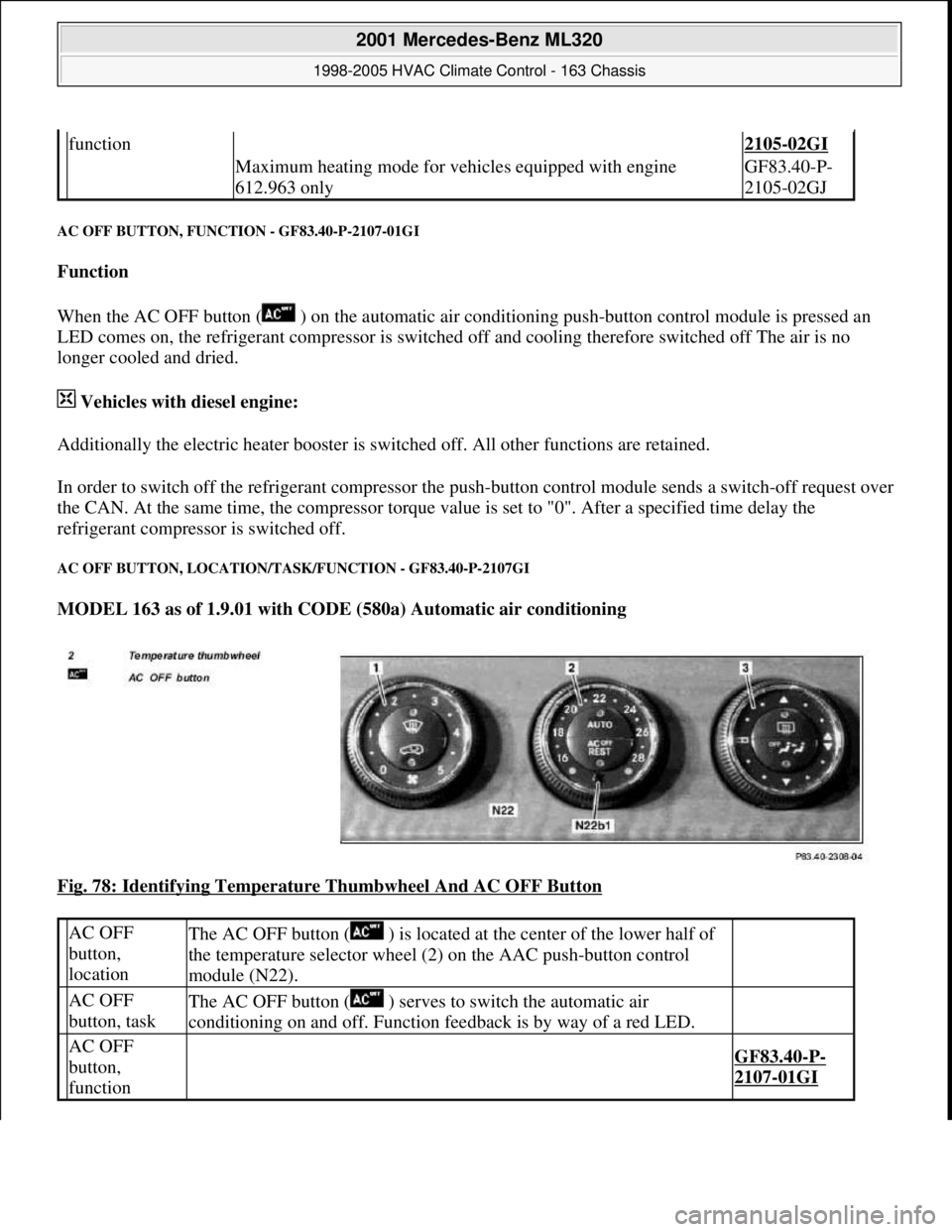
AC OFF BUTTON, LOCATION/TASK/FUNCTION - GF83.40-P-2107GI
MODEL 163 as of 1.9.01 with CODE (580a) Automatic air conditioning
Fig. 78: Identifying Temperature Thumbwheel And AC OFF Button
function2105-02GI
Maximum heating mode for vehicles equipped with engine
612.963 onlyGF83.40-P-
2105-02GJ
AC OFF
button,
locationThe AC OFF button ( ) is located at the center of the lower half of
the temperature selector wheel (2) on the AAC push-button control
module (N22).
AC OFF
button, taskThe AC OFF button ( ) serves to switch the automatic air
conditioning on and off. Function feedback is by way of a red LED.
AC OFF
button,
function
GF83.40-P-
2107-01GI
2001 Mercedes-Benz ML320
1998-2005 HVAC Climate Control - 163 Chassis
me
Saturday, October 02, 2010 3:23:16 PMPage 96 © 2006 Mitchell Repair Information Company, LLC.
Page 3341 of 4133
REST BUTTON, FUNCTION - GF83.40-P-2109-01GI
Function
Pressing the reset button ( ) on the AAC push-button control module (N22) switches on the residual engine
heat utilization system. When the engine is switched off, the residual heat heats the vehicle depending on the
temperature setting on the AAC push-button control panel (N22) and the ambient temperature in the vehicle
interior. The vehicle can be heated for approx. 30 min, with the engine switched off. The function is only
available with the ignition switched off or in position 1. If there is low voltage, the residual heat function is
automatically switched off.
The flaps are in automatic mode and the quantity of air is also automatically regulated.
The residual heat function is switched off,
if the electronic key is moved to position 2 in the starter switch,
after approx. 30 minutes,
if the battery voltage drops below 11V.
AUXILIARY FAN, FUNCTION - GF83.40-P-2115-01GH
Function
Depending on the refrigerant pressure and/or the coolant temperature the left auxiliary fan (M4m1), right
auxiliary fan (M4m2) are actuated.
The all-activity module (AAM) (N10) receives the coolant temperature from the coolant temperature sensor and
the refrigerant pressure from the refrigerant pressure sensor (B12).
The all-activity module (AAM) (N10) compares this input information with stored values and actuates the left
auxiliary fan (M4m1), right auxiliary fan (M4m2).
When the following values are indicated the left auxiliary fan (M4m1), right auxiliary fan (M4m2) are switched
on or off:
refrigerant pressure >16 bar = auxiliary fan ON
refrigerant pressure < 12 bar = auxiliary fan OFF
coolant temperature > 105°C = auxiliary fan ON
coolant temperature < 94°C = auxiliary fan OFF
AUXILIARY FAN, FUNCTION - GF83.40-P-2115-01GI
Function
Depending on the refrigerant pressure and/or the coolant temperature the left auxiliary fan (M4m1) and the right
auxiliary fan (M4m2) are actuated.
2001 Mercedes-Benz ML320
1998-2005 HVAC Climate Control - 163 Chassis
me
Saturday, October 02, 2010 3:23:16 PMPage 97 © 2006 Mitchell Repair Information Company, LLC.
Page 3342 of 4133
The all-activity module (AAM) (N10) receives the coolant temperature by the coolant temperature sensor
(B11/4) and the refrigerant pressure by the refrigerant pressure and temperature sensor (B12/2). The all-activity
module (AAM) (N10) compares this input information with stored values and actuates the left auxiliary fan
(M4m1) and the right auxiliary fan (M4m2).
When the following values are indicated the left auxiliary fan (M4m1), right auxiliary fan (M4m2) are switched
on or off:
refrigerant pressure >16 bar = auxiliary fan ON
refrigerant pressure <13 bar = auxiliary fan OFF
coolant temperature > 105°C = auxiliary fan ON
coolant temperature < 97°C = auxiliary fan OFF
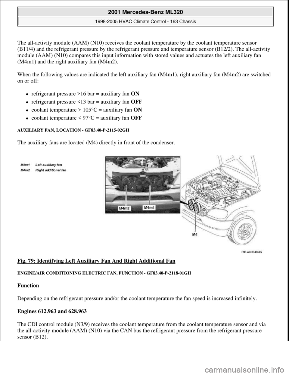
AUXILIARY FAN, LOCATION - GF83.40-P-2115-02GH
The auxiliary fans are located (M4) directly in front of the condenser.
Fig. 79: Identifying Left Auxiliary Fan And Right Additional Fan
ENGINE/AIR CONDITIONING ELECTRIC FAN, FUNCTION - GF83.40-P-2118-01GH
Function
Depending on the refrigerant pressure and/or the coolant temperature the fan speed is increased infinitely.
Engines 612.963 and 628.963
The CDI control module (N3/9) receives the coolant temperature from the coolant temperature sensor and via
the all-activity module (AAM) (N10) via the CAN bus the refrigerant pressure from the refrigerant pressure
sensor (B12).
2001 Mercedes-Benz ML320
1998-2005 HVAC Climate Control - 163 Chassis
me
Saturday, October 02, 2010 3:23:16 PMPage 98 © 2006 Mitchell Repair Information Company, LLC.
Page 3343 of 4133
This input information is relayed by the CDI control module (N3/9) to the integrated control module of the
electric engine/AC intake fan with integrated control (M4/7).
Engines 113.942 and 113.981
The all-activity module (AAM) (N10) receives the coolant temperature via the coolant temperature sensor and
the refrigerant pressure via the refrigerant pressure sensor (B12).
This input information is relayed by the all-activity module (AAM) (N10) to the integrated control module of
the engine and AC electric suction fan with integrated control (M4/7)
There the input information is compared with the stored values and, if necessary, the speed of the engine and
AC electric suction fan with integrated control (M4/7) is increased to 100 %.
The engine and AC electric suction fan with integrated control (M4/7) operates with AC switched on and in the
reheat mode for basic ventilation with a capacity of up to 20 %.
The basic ventilation can be switched off under the following conditions:
At an outdoor temperature of < or = 15°C the value of the outdoor temperature is transmitted from the
outside temperature sensor (B10/5) to the AC control module (N19).
The pressure-dependent fan speed remains the same.
At a vehicle speed of > 75 km/h
The vehicle speed value comes from the traction system control module via the instrument cluster (A1)
and CDI control module (N3/9), to the control module integrated in the electric suction fan engine and
AC with integrated control (M4/7). The pressure-dependent fan speed remains the same.
An overrun time of 60 s can be set in order to ensure that the engine and AC electric suction fan with integrated
control (M4/7) will continue to operate even where the refrigerant compressor is temporarily switched off by
the icing protection.
The engine and AC electric suction fan with integrated control (M4/7) has a power rating of 550W.
ELECTRIC FAN, ENGINE/AIR CONDITIONING, LOCATION - GF83.40-P-2118-02GH
The engine and AC electric suction fan with integrated control (M4/7) is located immediately in front of the
condenser.
2001 Mercedes-Benz ML320
1998-2005 HVAC Climate Control - 163 Chassis
me
Saturday, October 02, 2010 3:23:16 PMPage 99 © 2006 Mitchell Repair Information Company, LLC.
Page 3347 of 4133
Whenever the system is opened, the fluid reservoir should be replaced because of the water which has
collected there in the meantime.
EXPANSION VALVE, FUNCTION - GF83.40-P-2123-01GC
Function
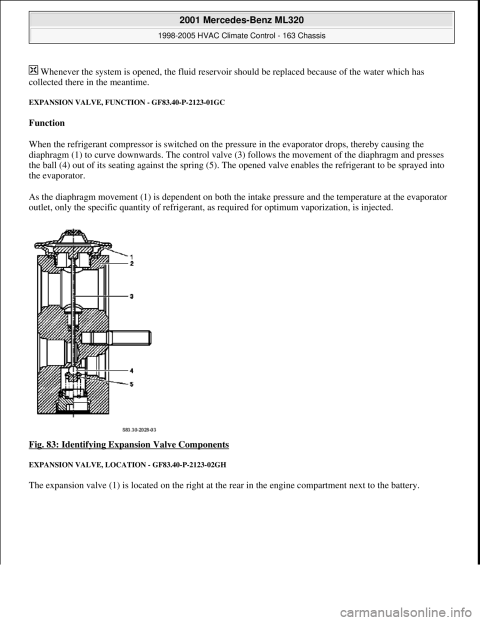
When the refrigerant compressor is switched on the pressure in the evaporator drops, thereby causing the
diaphragm (1) to curve downwards. The control valve (3) follows the movement of the diaphragm and presses
the ball (4) out of its seating against the spring (5). The opened valve enables the refrigerant to be sprayed into
the evaporator.
As the diaphragm movement (1) is dependent on both the intake pressure and the temperature at the evaporator
outlet, only the specific quantity of refrigerant, as required for optimum vaporization, is injected.
Fig. 83: Identifying Expansion Valve Components
EXPANSION VALVE, LOCATION - GF83.40-P-2123-02GH
The expansion valve (1) is located on the right at the rear in the engine compartment next to the battery.
2001 Mercedes-Benz ML320
1998-2005 HVAC Climate Control - 163 Chassis
me
Saturday, October 02, 2010 3:23:16 PMPage 103 © 2006 Mitchell Repair Information Company, LLC.
Page 3349 of 4133
Fig. 85: Identifying Expansion Valve Design
REFRIGERANT PRESSURE SENSOR, FUNCTION - GF83.40-P-2126-01GH
Function
Shutting off the refrigerant compressor
The refrigerant pressure sensor (B12) sends the current value to the All Activity Module (N10). The All
Activity Module (N10) compares this input information with stored values and actuates the refrigerant
compressor.
At the following values, the refrigerant compressor is switched on or off:
refrigerant pressure > 3 bar = refrigerant compressor ON
refrigerant pressure < 2 bar = refrigerant compressor OFF
refrigerant pressure < 26 bar = refrigerant compressor ON
refrigerant pressure > 30 bar = refrigerant compressor OFF
Cut-in of the auxiliary fan (engines 111.977 and 112.942)
The pressure value received from the refrigerant pressure sensor (B12) is recorded by the All Activity Module
(N10) and compared there with a stored value.
As of 12/99, the Extended Activity Module (EAM, N10/1) assumes this task from the All Activity Module
(N10).
At the following values, the auxiliary fan (M4m1, M4m2) is switched on or off:
refrigerant pressure > 16 bar = auxiliary fan ON
refrigerant pressure <12 bar = auxiliary fan OFF
Cut-in of the electric fan for engine/AC (engines 113.942/981 and 612.963)
The pressure value received from the refrigerant pressure sensor (B12) is recorded by the All Activity Module
(N10), sent to the control module inte
grated in the electric fan for engine/AC and compared there with a stored
Expansion valve,
locationModel 168GF83.40-P-2123-
02GC
Model 163GF83.40-P-2123-
02GH
Expansion valve, taskThe expansion valve injects the liquid refrigerant into the
evaporator.
Expansion valve,
function GF83.40-P-2123-
01GC
2001 Mercedes-Benz ML320
1998-2005 HVAC Climate Control - 163 Chassis
me
Saturday, October 02, 2010 3:23:16 PMPage 105 © 2006 Mitchell Repair Information Company, LLC.
Page 3350 of 4133
value.
At the following values the electric fan for engine/AC (M4/7) is switched on or off:
refrigerant pressure > 20 bar = electric fan for engine/AC ON
refrigerant pressure <12 bar = electric fan for engine/AC OFF
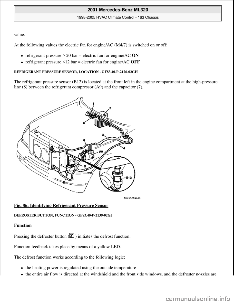
REFRIGERANT PRESSURE SENSOR, LOCATION - GF83.40-P-2126-02GH
The refrigerant pressure sensor (B12) is located at the front left in the engine compartment at the high-pressure
line (8) between the refrigerant compressor (A9) and the capacitor (7).
Fig. 86: Identifying Refrigerant Pressure Sensor
DEFROSTER BUTTON, FUNCTION - GF83.40-P-2139-02GI
Function
Pressing the defroster button ( ) initiates the defrost function.
Function feedback takes place by means of a yellow LED.
The defrost function works according to the following logic:
the heating power is regulated using the outside temperature
the entire air flow is directed at the windshield and the front side windows, and the defroster nozzles are
2001 Mercedes-Benz ML320
1998-2005 HVAC Climate Control - 163 Chassis
me
Saturday, October 02, 2010 3:23:16 PMPage 106 © 2006 Mitchell Repair Information Company, LLC.