1997 MERCEDES-BENZ ML320 engine
[x] Cancel search: enginePage 3385 of 4133
The in-car temperature sensor (B10/4) is equipped with an aspirator blower which constantly draws air out of
the vehicle interior for the temperature measurement when the ignition is ON . The in-car temperature sensor
(B10/4) records the interior temperature and conveys it to the AAC push-button control module. A comparison
is made there with the setting on the temperature selector and the blend air flap is repositioned depending on the
result of this comparison.
It is connected to the AAC push-button control module via a separate electric cable.
Constant circulation of the interior air at the in-car temperature sensor (B10/4) is achieved by the in-car
temperature sensor aspirator blower (M9) and therefore ensures a high level of control accuracy.
In contrast to the previous suction jet nozzle a high level of control accuracy is ensured by the in-car
temperature sensor aspirator blower (M9).
OUTSIDE AIR TEMPERATURE SENSOR FUNCTION - GF83.57-P-2103-01GH
Function
The resistance of the outside air temperature sensor (B10/5) depends on the ambient temperature and the ground
speed. With an increase in the outside temperature, its resistance decreases. This information is sent to the air
conditioning control module (N19). This information causes a slight lowering or raising of the temperature
selected at the air conditioning control panel.
This achieves an adaptation to the temperature perception of the occupants.
The outside temperature depends on the ground speed, which prevents a value for the outside temperature that is
too high - as may occur when the vehicle is stationary or when traveling slowly, e.g. due to thermal radiation
from the engine - from being sent to the air conditioning control module (N19).
The value of the ground speed is sent from the traction systems control module (N47) via the instrument cluster
(A1) to the air conditioning control module (N19).
When switching the ignition off and on and with speeds lower than 20 km/h the temperature measured last is
used.
OUTSIDE AIR TEMPERATURE SENSOR POSITION - GF83.57-P-2103-02GH
The outside air temperature sensor (B10/5) is located at the front on the air inlet of the evaporator housing.
2001 Mercedes-Benz ML320
1998-2005 HVAC Climate Control - 163 Chassis
me
Saturday, October 02, 2010 3:23:17 PMPage 141 © 2006 Mitchell Repair Information Company, LLC.
Page 3395 of 4133
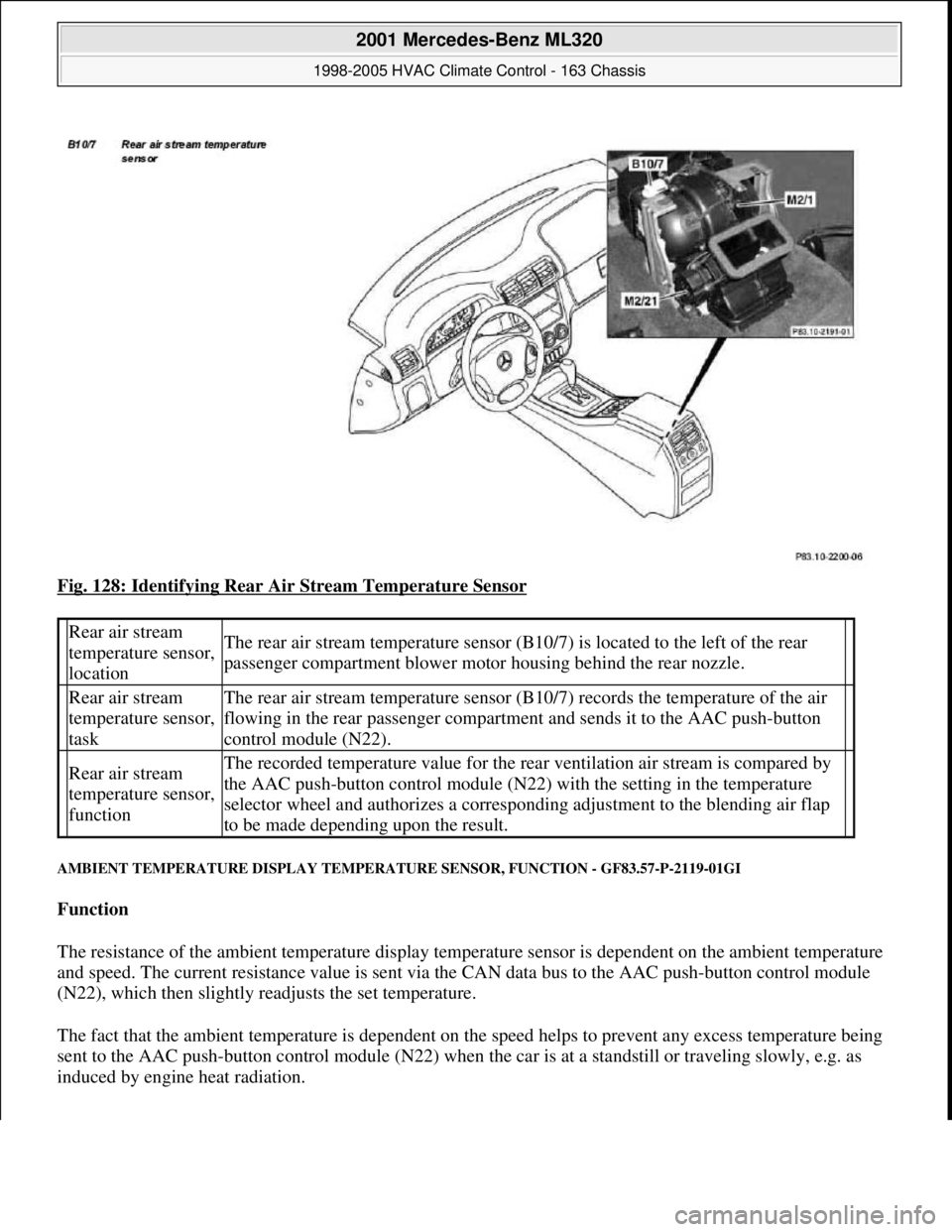
Fig. 128: Identifying Rear Air Stream Temperature Sensor
AMBIENT TEMPERATURE DISPLAY TEMPERATURE SENSOR, FUNCTION - GF83.57-P-2119-01GI
Function
The resistance of the ambient temperature display temperature sensor is dependent on the ambient temperature
and speed. The current resistance value is sent via the CAN data bus to the AAC push-button control module
(N22), which then slightly readjusts the set temperature.
The fact that the ambient temperature is dependent on the speed helps to prevent any excess temperature being
sent to the AAC push-button control module (N22) when the car is at a standstill or traveling slowly, e.g. as
induced b
y engine heat radiation.
Rear air stream
temperature sensor,
locationThe rear air stream temperature sensor (B10/7) is located to the left of the rear
passenger compartment blower motor housing behind the rear nozzle.
Rear air stream
temperature sensor,
taskThe rear air stream temperature sensor (B10/7) records the temperature of the air
flowing in the rear passenger compartment and sends it to the AAC push-button
control module (N22).
Rear air stream
temperature sensor,
functionThe recorded temperature value for the rear ventilation air stream is compared by
the AAC push-button control module (N22) with the setting in the temperature
selector wheel and authorizes a corresponding adjustment to the blending air flap
to be made depending upon the result.
2001 Mercedes-Benz ML320
1998-2005 HVAC Climate Control - 163 Chassis
me
Saturday, October 02, 2010 3:23:17 PMPage 151 © 2006 Mitchell Repair Information Company, LLC.
Page 3396 of 4133
When switching the ignition on or off and at speeds of less than 20 km/h the last measured temperature value is
used.
At ignition OFF, the last ambient temperature used for the control operation is stored.
AMBIENT TEMPERATURE DISPLAY TEMPERATURE SENSOR, LOCATION/TASK/FUNCTION - GF83.57-P-2119GI
MODEL 163 as of 1.9.01 with CODE (580a) Automatic air conditioning
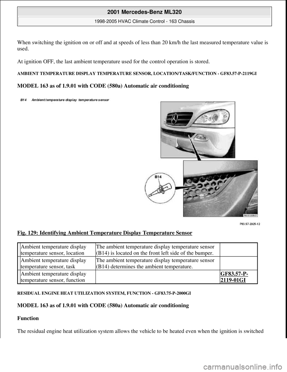
Fig. 129: Identifying Ambient Temperature Display Temperature Sensor
RESIDUAL ENGINE HEAT UTILIZATION SYSTEM, FUNCTION - GF83.75-P-2000GI
MODEL 163 as of 1.9.01 with CODE (580a) Automatic air conditioning
Function
The residual en
gine heat utilization system allows the vehicle to be heated even when the ignition is switched
Ambient temperature display
temperature sensor, locationThe ambient temperature display temperature sensor
(B14) is located on the front left side of the bumper.
Ambient temperature display
temperature sensor, taskThe ambient temperature display temperature sensor
(B14) determines the ambient temperature.
Ambient temperature display
temperature sensor, function GF83.57-P-
2119-01GI
2001 Mercedes-Benz ML320
1998-2005 HVAC Climate Control - 163 Chassis
me
Saturday, October 02, 2010 3:23:17 PMPage 152 © 2006 Mitchell Repair Information Company, LLC.
Page 3397 of 4133
OFF . To this end the system uses the residual heat of the engine. The residual engine heat is dissipated to the
coolant and routed through the heat exchanger with the aid of the heating water circulation pump. The air drawn
in by the blower motor is routed around the heat exchanger, whereby it is then warmed up. The heated air is
then routed over the air outlets into the passenger compartment.
The residual engine heat utilization system can only be used when the ignition is switched OFF.
Once the Rest push-button ( ) on the AAC push-button control module (N22) has been pressed the
following program sequence is run:
Blending air flaps are automatically controlled
Heating water circulation pump ON
The blower's control voltage is limited to a maximum value of 5 Volt.
End of program
Pressing the Rest push-button ( )
Timeout of 30 minutes period (repeated operation possible)
Protection against undervoltage at a battery voltage of less than 11 V (LED flashes)
Ignition ON
During the residual engine heat utilization function no function keys are accepted apart from the Rest push-
button ( ) and the set point adjusters.
SAFETY PRECAUTIONS
RISK OF EXPLOSION CAUSED BY WELDING OR SOLDERING WORK ON CLOSED AIR CONDITIONING SYSTEM.
RISK OF POISONING CAUSED BY INHALING OVERHEATED REFRIGERANT VAPORS. RISK OF INJURY TO SKIN AND
EYES CAUSED BY CONTACT WITH LIQUID REFRIGERANT. - AS83.00-Z-0001-01A
Never perform welding work on or near a closed air conditioning system. No smoking or open flames.
Wear safety glasses and protective gloves. Work only in well ventilated areas. Carry out repair work on
the air conditioning system circuit only after the system has been discharged.
Potential risks
Risk of explosion
When closed air conditionin
g systems (charged or empty) become heated, high pressures are produced that can
Rest push-button, location/task/function GF83.40-P-2148GI
Heating water circulation pump, location/task/ function GF83.20-P-2109GI
Heating system heat exchanger, location/ purpose/function GF83.20-P-2108GC
Blower motor, location/task/design/function GF83.10-P-2170GI
Blending air flap actuator, location/task/function GF83.57-P-2112GI
2001 Mercedes-Benz ML320
1998-2005 HVAC Climate Control - 163 Chassis
me
Saturday, October 02, 2010 3:23:17 PMPage 153 © 2006 Mitchell Repair Information Company, LLC.
Page 3402 of 4133
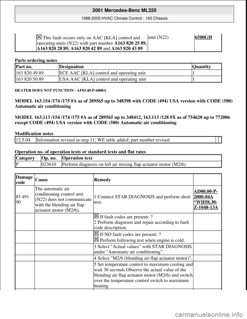
Parts ordering notes
HEATER DOES NOT FUNCTION - AF83.40-P-6008A
MODEL 163.154 /174 /175 #A as of 289565 up to 348398 with CODE (494) USA version with CODE (580)
Automatic air conditioning
MODEL 163.113 /154 /174 /175 #A as of 289565 up to 348412, 163.113 /128 #X as of 754620 up to 772006
except CODE (494) USA version with CODE (580) Automatic air conditioning
Modification notes
Operation no. of operation texts or standard texts and flat rates
This fault occurs only on AAC [KLA] control and
operating units (N22) with part number A163 820 25 89,
A163 820 28 89, A163 820 42 89 and A163 820 43 89 unit (N22)6500GH
Part no.DesignationQuantity
163 820 49 89ECE AAC [KLA] control and operating unit1
163 820 50 89USA AAC [KLA] control and operating unit1
12.5.04Information revised in step 11; WE table added; part number revised
CategoryOp. no.Operation text
P023610Perform diagnosis on left air mixing flap actuator motor (M2/6)
Damage
codeCauseRemedy
83 491
90
The automatic air
conditioning control unit
(N22) does not communicate
with the blending air flap
actuator motor (M2/6).
1 Connect STAR DIAGNOSIS and perform short
test.
AD00.00-P-
2000-04A
*WH58.30
-
Z-1048-13A
If fault codes are present: ?
2 Perform diagnosis and repair according to fault
code description.
If NO fault codes are present: ?
Perform following test when engine is cold.
3 Select "Actual values" with STAR DIAGNOSIS
under "Automatic air conditioning".
4 Select "M2/6 (blending air flap actuator motor)".
5 Set temperature control to maximum cooling and
wait 30 seconds Observe the actual value of the
blending air flap actuator motor (M2/6) and switch
over the temperature control switch to maximum
heating.
2001 Mercedes-Benz ML320
1998-2005 HVAC Climate Control - 163 Chassis
me
Saturday, October 02, 2010 3:23:17 PMPage 158 © 2006 Mitchell Repair Information Company, LLC.
Page 3404 of 4133
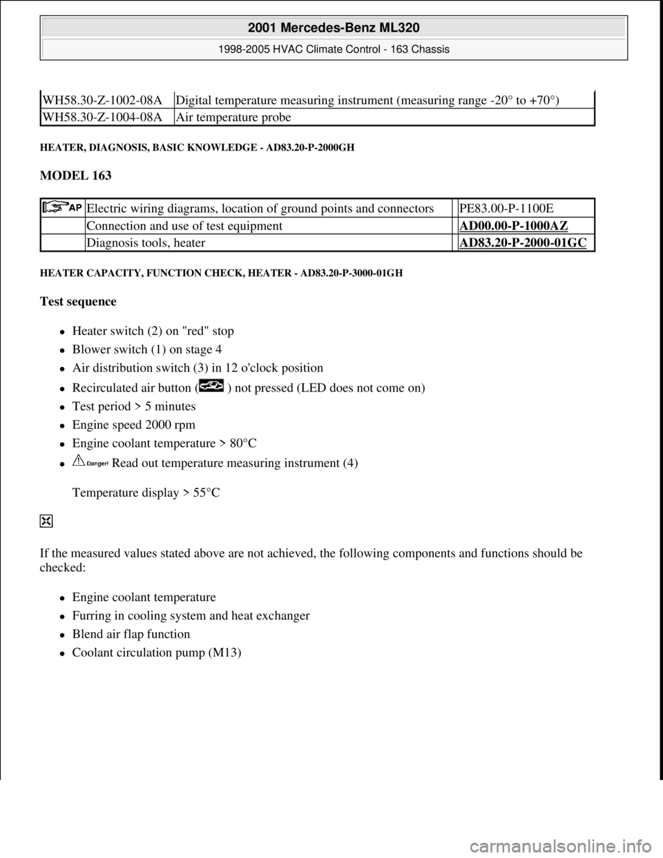
HEATER, DIAGNOSIS, BASIC KNOWLEDGE - AD83.20-P-2000GH
MODEL 163
HEATER CAPACITY, FUNCTION CHECK, HEATER - AD83.20-P-3000-01GH
Test sequence
Heater switch (2) on "red" stop
Blower switch (1) on stage 4
Air distribution switch (3) in 12 o'clock position
Recirculated air button ( ) not pressed (LED does not come on)
Test period > 5 minutes
Engine speed 2000 rpm
Engine coolant temperature > 80°C
Read out temperature measuring instrument (4)
Temperature display > 55°C
If the measured values stated above are not achieved, the following components and functions should be
checked:
Engine coolant temperature
Furring in cooling system and heat exchanger
Blend air flap function
Coolant circulation pump (M13)
WH58.30-Z-1002-08ADigital temperature measuring instrument (measuring range -20° to +70°)
WH58.30-Z-1004-08AAir temperature probe
Electric wiring diagrams, location of ground points and connectors PE83.00-P-1100E
Connection and use of test equipment AD00.00-P-1000AZ
Diagnosis tools, heater AD83.20-P-2000-01GC
2001 Mercedes-Benz ML320
1998-2005 HVAC Climate Control - 163 Chassis
me
Saturday, October 02, 2010 3:23:17 PMPage 160 © 2006 Mitchell Repair Information Company, LLC.
Page 3405 of 4133
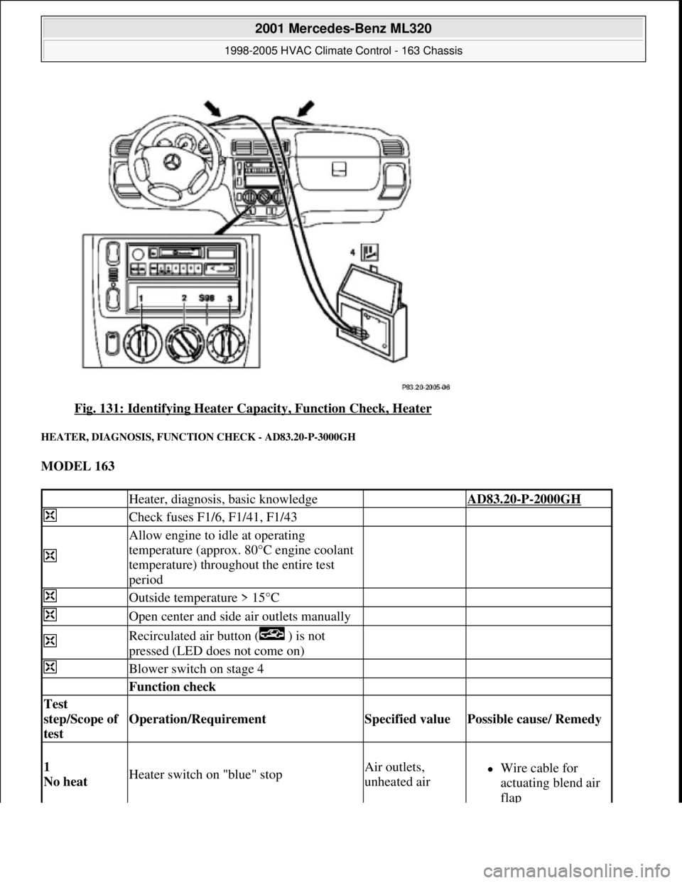
Fig. 131: Identifying Heater Capacity, Function Check, Heater
HEATER, DIAGNOSIS, FUNCTION CHECK - AD83.20-P-3000GH
MODEL 163
Heater, diagnosis, basic knowledge AD83.20-P-2000GH
Check fuses F1/6, F1/41, F1/43
Allow engine to idle at operating
temperature (approx. 80°C engine coolant
temperature) throughout the entire test
period
Outside temperature > 15°C
Open center and side air outlets manually
Recirculated air button ( ) is not
pressed (LED does not come on)
Blower switch on stage 4
Function check
Test
step/Scope of
test
Operation/Requirement Specified value Possible cause/ Remedy
1
No heat Heater switch on "blue" stopAir outlets,
unheated airWire cable for
actuating blend air
flap
2001 Mercedes-Benz ML320
1998-2005 HVAC Climate Control - 163 Chassis
me
Saturday, October 02, 2010 3:23:17 PMPage 161 © 2006 Mitchell Repair Information Company, LLC.
Page 3406 of 4133
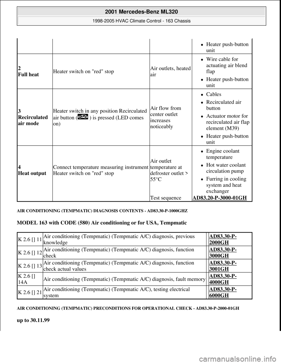
AIR CONDITIONING (TEMPMATIC) DIAGNOSIS CONTENTS - AD83.30-P-1000GHZ
MODEL 163 with CODE (580) Air conditioning or for USA, Tempmatic
AIR CONDITIONING (TEMPMATIC) PRECONDITIONS FOR OPERATIONAL CHECK - AD83.30-P-2000-01GH
up to 30.11.99
Heater push-button
unit
2
Full heat Heater switch on "red" stopAir outlets, heated
air
Wire cable for
actuating air blend
flap
Heater push-button
unit
3
Recirculated
air mode Heater switch in any position Recirculated
air button ( ) is pressed (LED comes
on)Air flow from
center outlet
increases
noticeably
Cables
Recirculated air
button
Actuator motor for
recirculated air flap
element (M39)
Heater push-button
unit
4
Heat output Connect temperature measuring instrument
Heater switch on "red" stop
Air outlet
temperature at
defroster outlet >
55°C
Engine coolant
temperature
Hot water coolant
circulation pump
Furring in cooling
system and heat
exchanger
Test sequenceAD83.20-P-3000-01GH
K 2.6 [] 11Air conditioning (Tempmatic) (Tempmatic A/C) diagnosis, previous
knowledge AD83.30-P-
2000GH
K 2.6 [] 12Air conditioning (Tempmatic) (Tempmatic A/C) diagnosis, function
check AD83.30-P-
3000GH
K 2.6 [] 13Air conditioning (Tempmatic) (Tempmatic A/C) diagnosis, function
check actual values AD83.30-P-
3001GH
K 2.6 []
14AAir conditioning (Tempmatic) (Tempmatic A/C) diagnosis, fault memory AD83.30-P-
4000GH
K 2.6 [] 21Air conditioning (Tempmatic) (Tempmatic A/C), testing electrical
system AD83.30-P-
6000GH
2001 Mercedes-Benz ML320
1998-2005 HVAC Climate Control - 163 Chassis
me
Saturday, October 02, 2010 3:23:17 PMPage 162 © 2006 Mitchell Repair Information Company, LLC.