Page 3513 of 4133
AR91.60-P-0680GH
Remove/install passenger airbag unit
27.2.01
MODEL
163.113 /128 /136 /154 /157 /172 /174 /175
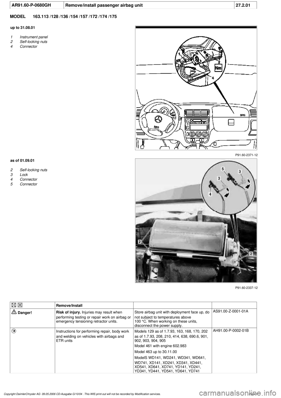
P91.60-2371-12
up to 31.08.01
1
Instrument panel
2
Self-locking nuts
4
Connector
P91.60-2337-12
as of 01.09.01
2
Self-locking nuts
3
Lock
4
Connector
5
Connector
Remove/Install
Danger!
Risk of injury.
Injuries may result when
performing testing or repair work on airbag or
emergency tensioning retractor units.
Store airbag unit with deployment face up, do
not subject to temperatures above
100 °C. When working on these units,
disconnect the power supply.
AS91.00-Z-0001-01A
Instructions for performing repair, body work
and welding on vehicles with airbags and
ETR units
Models 129 as of 1.7.93, 163, 168, 170, 202
as of 1.7.93, 208, 210, 414, 638, 690.6, 901,
902, 903, 904, 905
Model 461 with engine 602.983
Model 463 up to 30.11.00
ModelS WD141, WD241, WD341, WD641,
WD741, XD141, XD241, XD341, XD441,
XD541, XD641, XD741, YD141, YD241,
YD341, YD441, YD541, YD641, YD741
AH91.00-P-0002-01B
Copyright DaimlerChrysler AG 09.05.2006 CD-Ausgabe G/10/04 . This WIS print-out will not be recorde
d by Modification services.
Page 1
Page 3518 of 4133
AR07.52-P-1465A
Remove/install intake air temperature sensor
16.2.99
ENGINE
604, 611.960 /961 /962, 612.961 /962 /963 /967, 613.961 /960, 628.960
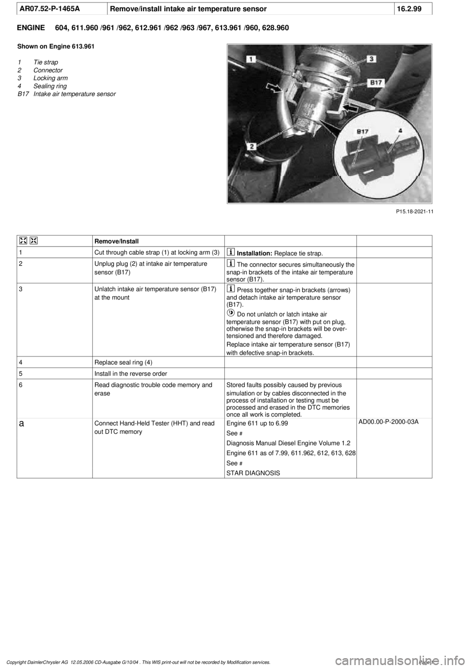
P15.18-2021-11
Shown on Engine 613.961
1
Tie strap
2
Connector
3
Locking arm
4
Sealing ring
B17
Intake air temperature sensor
Remove/Install
1
Cut through cable strap (1) at locking arm (3)
Installation:
Replace tie strap.
2
Unplug plug (2) at intake air temperature
sensor (B17)
The connector secures simultaneously the
snap-in brackets of the intake air temperature
sensor (B17).
3
Unlatch intake air temperature sensor (B17)
at the mount
Press together snap-in brackets (arrows)
and detach intake air temperature sensor
(B17).
Do not unlatch or latch intake air
temperature sensor (B17) with put on plug,
otherwise the snap-in brackets will be over-
tensioned and therefore damaged.
Replace intake air temperature sensor (B17)
with defective snap-in brackets.
4
Replace seal ring (4)
5
Install in the reverse order
6
Read diagnostic trouble code memory and
erase
Stored faults possibly caused by previous
simulation or by cables disconnected in the
process of installation or testing must be
processed and erased in the DTC memories
once all work is completed.
a
Connect Hand-Held Tester (HHT) and read
out DTC memory
Engine 611 up to 6.99
See
#
AD00.00-P-2000-03A
Diagnosis Manual Diesel Engine Volume 1.2
Engine 611 as of 7.99, 611.962, 612, 613, 628
See
#
STAR DIAGNOSIS
Copyright DaimlerChrysler AG 12.05.2006 CD-Ausgabe G/10/04 . This WIS print-out will not be recorde
d by Modification services.
Page 1
Page 3576 of 4133
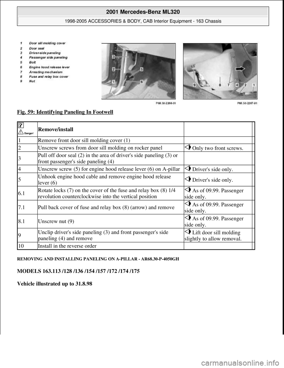
Fig. 59: Identifying Paneling In Footwell
REMOVING AND INSTALLING PANELING ON A-PILLAR - AR68.30-P-4050GH
MODELS 163.113 /128 /136 /154 /157 /172 /174 /175
Vehicle illustrated up to 31.8.98
Remove/install
1Remove front door sill molding cover (1)
2Unscrew screws from door sill molding on rocker panel Only two front screws.
3Pull off door seal (2) in the area of driver's side paneling (3) or
front passenger's side paneling (4)
4Unscrew screw (5) for engine hood release lever (6) on A-pillar Driver's side only.
5Unhook engine hood cable and remove engine hood release
lever (6) Driver's side only.
6.1Rotate locks (7) on the cover of the fuse and relay box (8) 1/4
revolution counterclockwise into the vertical position As of 09.99. Passenger
side only.
7.1Pull back cover of fuse and relay box (8) (arrow) and remove As of 09.99. Passenger
side only.
8.1Unscrew nut (9) As of 09.99. Passenger
side only.
9Unclip driver's side paneling (3) and front passenger's side
paneling (4) and remove Lift door sill molding
slightly to allow removal.
10Install in the reverse order
2001 Mercedes-Benz ML320
1998-2005 ACCESSORIES & BODY, CAB Interior Equipment - 163 Chassis
me
Saturday, October 02, 2010 3:35:22 PMPage 58 © 2006 Mitchell Repair Information Company, LLC.
Page 3716 of 4133
AF07.07-P-2700A
Oil consumption too high
28.1.03
ENGINE
112, 113 in MODEL 163.1## ## up to 357786
ENGINE
112 in MODEL 202.02
ENGINE
112 in MODEL 202.08
ENGINE
112 in MODEL 210.06
ENGINE
113 in MODEL 210.07
ENGINE
112 in MODEL 210.663
ENGINE
112 in MODEL 210.26# ## up to 276396
ENGINE
113 in MODEL 210.27# ## up to 276396
ENGINE
112, 113 in MODEL 210.08# ## up to 084039
ENGINE
112, 113 in MODEL 210.28# ## up to 084039
Operation no. of operation texts or standard texts and flat rates
Category
Op. no.
Operation text
Time
Acc. no.
Code
P
023813
Remove/install/replace gasket between intake pipe and throttle
valve
006 WU/0.5 h
------
Damage code
Cause
Remedy
14 034 04
Gasket (B) between intake pipe (A) and
throttle valve defective.
High oil consumption of more than 0.8
liters per 1000 km.
In order to avoid erroneous removal the
following documents
must
be processed
before starting the work:
#
High oil consumption
AF18.00-P-8044D
Measure oil consumption
AR18.00-P-0025AV
1
Remove,/install/replace gasket (B)
between intake pipe (A) and throttle
valve.
AR07.07-P-1454A
Use new gasket according to parts
ordering notes Old gasket with part number
112 141 01 80 should no longer be used.
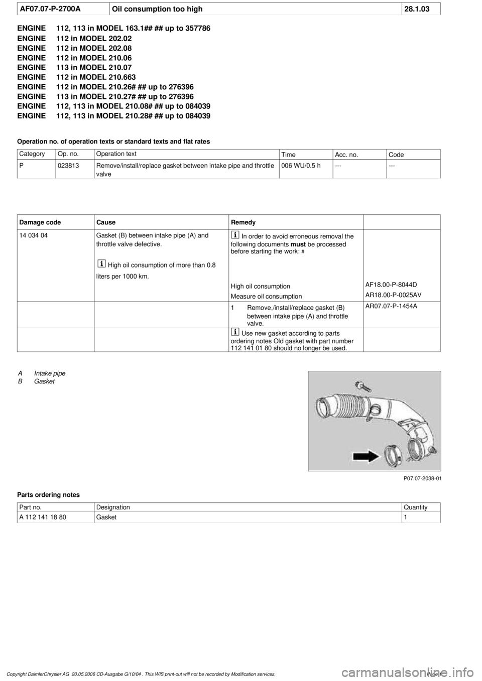
P07.07-2038-01
A
Intake pipe
B
Gasket
Parts ordering notes
Part no.
Designation
Quantity
A 112 141 18 80
Gasket
1
Copyright DaimlerChrysler AG 20.05.2006 CD-Ausgabe G/10/04 . This WIS print-out will not be recorde
d by Modification services.
Page 1
Page 3718 of 4133
AP18.00-P-0101-06GH
Replacing oil filter element, draining oil filter
Oil filter
Number
Designation
Engines
112.910/911/
912/913/914/
915/916/917/
920/921/922/
923/940/941/
942/943/944/
945/946/947/
949/951/953/
954/955/960/
961/970/972/
973/975
Engines
113.940/941/
942/943/944/
945/946/948/
960/961/962/
963/965/966/
967/968/969/
980/981/982/
984/986
Engines
113.990/
991/993
BA18.20-P-1001-01D
Screw cap on oil filter
Nm
252525
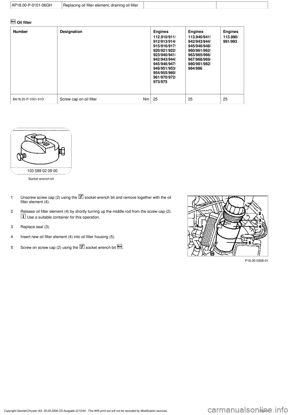
103 589 02 09 00
Socket wrench bit
1
Unscrew screw cap (2) using the
socket wrench bit and remove together with the oil
filter element (4).
2
Release oil filter element (4) by shortly turning up the middle rod from the screw cap (2).
Use a suitable container for this operation.
3
Replace seal (3).
4
Insert new oil filter element (4) into oil filter housing (5).
5
Screw on screw cap (2) using the
socket wrench bit
.
P18.00-0308-01
Copyright DaimlerChrysler AG 20.05.2006 CD-Ausgabe G/10/04 . This WIS print-out will not be recorde
d by Modification services.
Page 1
Page 3719 of 4133
AP18.00-P-0101-06EG
Replace oil filter element, drain oil filter
Crankcase ventilation, cylinder head cover
Number
Designation
Engine
611.960/
961/962
Engine
612.961/
962/967
Engine
612.963
Engine
612.965/
966
Engine
613.960/
961
BA01.20-P-1002-01A
Screw of trim panel of cylinder head cover
to cylinder head cover
Nm
1010101010
BA01.20-P-1003-01A
Screw attaching cover panel to charge air
distribution pipe
Nm
1010101010
Crankcase ventilation, cylinder head cover
Number
Designation
Engine
646.951/961,
647
Engine
646.962/963
Engine
648
BA01.20-P-1002-01G
Bolt, trim panel of cylinder
head cover to cylinder head
Nm
999
BA01.20-P-1003-01G
Bolt, cover to charge air
distribution pipe.
Nm
999
Designation
Engine
611.960/
961/962
Engine
612.961/962/
963/990,
613.960/961
Engine
612.965/
966
Engine
646.951/961/
962/963/982/
983/984,
647, 648
BA18.20-P-1002-01G
Screw cap at oil filter
Nm
25252525
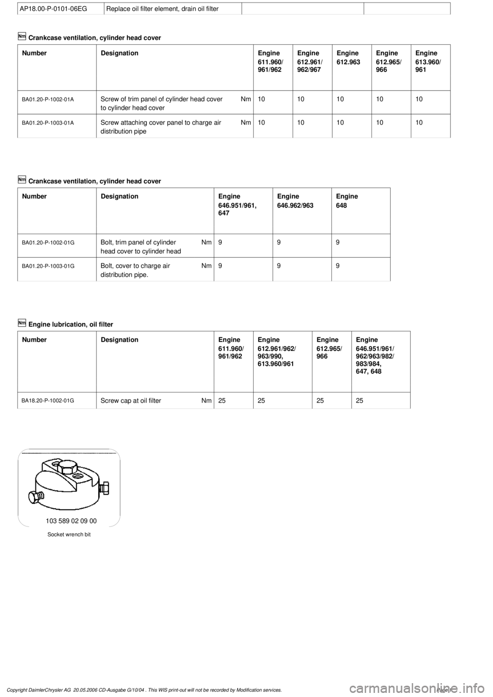
Socket wrench bit
103 589 02 09 00
Copyright DaimlerChrysler AG 20.05.2006 CD-Ausgabe G/10/04 . This WIS print-out will not be recorde
d by Modification services.
Page 1
Page 3720 of 4133
P18.20-2022-01
1
Engine 611.961 as of 07.99, 611.962, 612, 613, 646, 647, 648:
Remove trim panel of cylinder head cover and trim panel of charge air distribution pipe.
2
Model 203, 211:
Remove fastening clamp (arrow) of fuel line.
3
Remove screw cap (1) with wrench socket
and take off together with oil filter element
(3).
4
Replace seal (2).
5
Insert new oil filter element (3) into oil filter housing.
6
Fasten the screw cap (1) with bolts using a socket wrench bit
.
7
Model 203, 211:
Install the fastening clamp (arrow) of the fuel line.
8
Engine 611.961 as of 07.99, 611.962, 612, 613, 646, 647, 648:
Install the cylinder head cover trim panel and the charge air distribution pipe trim panel
.
Copyright DaimlerChrysler AG 20.05.2006 CD-Ausgabe G/10/04 . This WIS print-out will not be recorde
d by Modification services.
Page 2
Page 3721 of 4133
AF01.40-P-4000AU
Oil leak out of drain opening on left side of engine (cylinder 6)
21.1.98
ENGINE
112 in MODEL 129, 163, 170, 202, 203, 208, 210, 220
ENGINE
113 in MODEL 129, 163, 202, 208, 210, 215, 220
ENGINE
112 in MODEL 463
ENGINE
113 in MODEL 463
Modification notes
23.3.99
Supersedes STIP no. 01.40-004 dated 15.1.98
Validity and cause modified
Damage code
Cause
Remedy
Threaded connection of oil duct in
front of crankcase V is installed without or
with a damaged sealing ring.
Consequently, engine oil in V of crankcase
below intake module. Engine oil flows out of
drain opening on left side of engine behind
cylinder 6 and 8 resp.
1
Remove intake module
2
Replace sealing ring
Parts ordering notes
Part no.
Designation
Quantity
023 997 70 48
Sealing ring
1
Copyright DaimlerChrysler AG 20.05.2006 CD-Ausgabe G/10/04 . This WIS print-out will not be recorde
d by Modification services.
Page 1