1997 MERCEDES-BENZ ML320 engine
[x] Cancel search: enginePage 3723 of 4133
GF18.40-P-4111-02A
Oil sensor function
n
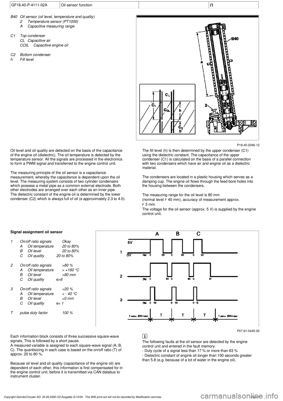
P18.40-2046-12
B40
Oil sensor (oil level, temperature and quality)
2
Temperature sensor (PT1000)
A
Capacitive measuring range
C 1
Top condenser
C L
Capacitive air
C
OIL
Capacitive engine oil
C 2
Bottom condenser
h
Fill level
Oil level and oil quality are detected on the basis of the capacitance
of the engine oil (dielectric). The oil temperature is detected by the
temperature sensor. All the signals are processed in the electronics
to form a PWM signal and transferred to the engine control unit.
The measuring principle of the oil sensor is a capacitance
measurement, whereby the capacitance is dependent upon the oil
level. The measuring system consists of two cylinder condensers
which possess a metal pipe as a common external electrode. Both
other electrodes are arranged over each other as an inner pipe.
The dielectric constant of the engine oil is determined by the lower
condenser (C
2
) which is always full of oil (
e
approximately 2.3 to 4.0).
The fill level (h) is then determined by the upper condenser (C
1
)
using the dielectric constant. The capacitance of the upper
condenser (C
1
) is calculated on the basis of a parallel connection
with two condensers which have air and engine oil as a dielectric
material.
The condensers are located in a plastic housing which serves as a
damping cup. The engine oil flows through the feed bore holes into
the housing between the condensers.
The measuring range for the oil level is 80 mm
(normal level
F
40 mm), accuracy of measurement approx.
F
3 mm.
The voltage for the oil sensor (approx. 5 V) is supplied by the engine
control unit.
P07.61-0445-05
Signal assignment oil sensor
1
On/off ratio signals
Okay
A
Oil temperature
20 to 80%
B
Oil level
20 to 80%
C
Oil quality
20 to 80%
2
On/off ratio signals
>80 %
A
Oil temperature
> +160 °C
B
Oil level
>80 mm
C
Oil quality
e
>6
3
On/off ratio signals
<20 %
A
Oil temperature
< - 40 °C
B
Oil level
<0 mm
C
Oil quality
e
< 1
T
pulse duty factor
100 %
Each information block consists of three successive square-wave
signals, This is followed by a short pause.
A measured variable is assigned to each square-wave signal (A, B,
C). The quantisizing in each case is based on the on/off ratio (T) of
approx. 20 to 80 %.
Because oil level and oil quality (capacitance of the engine oil) are
dependent of each other, this information is first compensated for in
the engine control unit, before it is transmitted via CAN databus to
instrument cluster.
The following faults at the oil sensor are detected by the engine
control unit and entered in the fault memory:
- Duty cycle of a signal less than 17 % or more than 83 %
- Dielectric constant of engine oil longer than 100 seconds greater
than 5.8 (e.g. because of a lot of water in the engine oil).
Copyright DaimlerChrysler AG 05.06.2006 CD-Ausgabe G/10/04 . This WIS print-out will not be recorde
d by Modification services.
Page 1
Page 3724 of 4133
GF18.40-P-4111A
Oil sensor, location/task/design/function
15.10.96
ENGINE
111.951 /955 /956 /957 /982
ENGINE
112.910 /911 /912 /913 /914 /916 /917 /920 /921 /922 /923 /940 /941 /942 /943 /944 /946 /947 /949 /9 53 /954 /955
/970 /972 /973 /975
ENGINE
113.940 /941 /942 /943 /948 /960 /961 /963 /965 /966 /967 /968 /969
ENGINE
166.940 /960 /990 /995
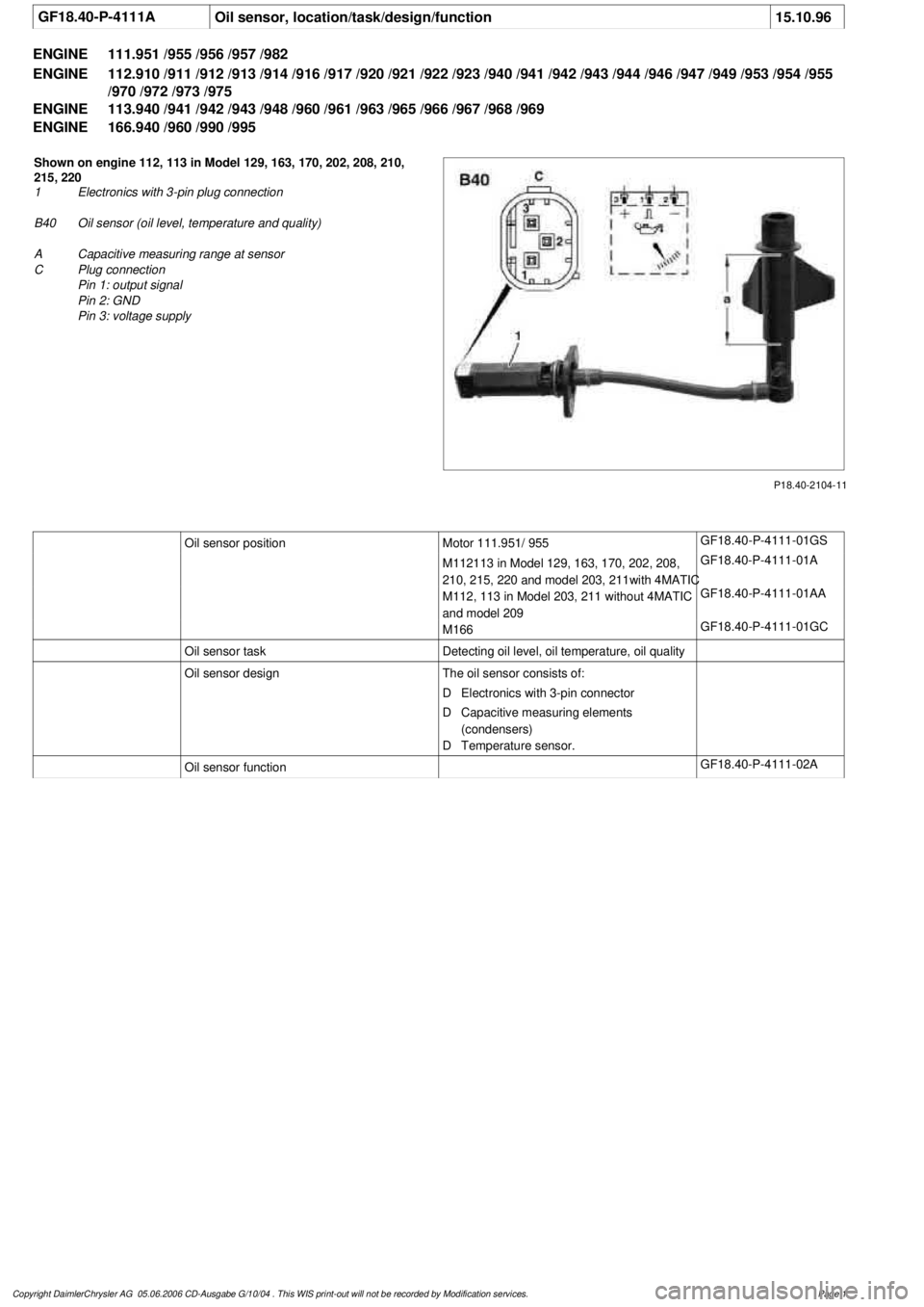
P18.40-2104-11
Shown on engine 112, 113 in Model 129, 163, 170, 202, 208, 210,
215, 220
1
Electronics with 3-pin plug connection
B40
Oil sensor (oil level, temperature and quality)
A
Capacitive measuring range at sensor
C
Plug connection
Pin 1: output signal
Pin 2: GND
Pin 3: voltage supply
Oil sensor position
Motor 111.951/ 955
GF18.40-P-4111-01GS
M112113 in Model 129, 163, 170, 202, 208,
210, 215, 220 and model 203, 211with 4MATIC
GF18.40-P-4111-01A
M112, 113 in Model 203, 211 without 4MATIC
and model 209
GF18.40-P-4111-01AA
M166
GF18.40-P-4111-01GC
Oil sensor task
Detecting oil level, oil temperature, oil quality
Oil sensor design
The oil sensor consists of:
D
Electronics with 3-pin connector
D
Capacitive measuring elements
(condensers)
D
Temperature sensor.
Oil sensor function
GF18.40-P-4111-02A
Copyright DaimlerChrysler AG 05.06.2006 CD-Ausgabe G/10/04 . This WIS print-out will not be recorde
d by Modification services.
Page 1
Page 3725 of 4133
GF18.40-P-4111-01A
Oil sensor position
n
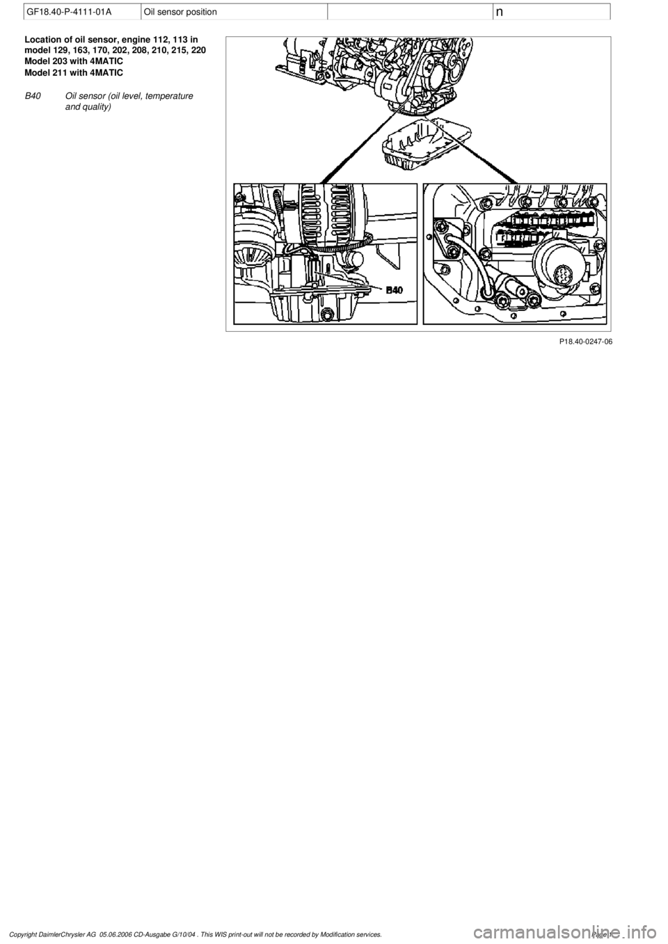
P18.40-0247-06
Location of oil sensor, engine 112, 113 in
model 129, 163, 170, 202, 208, 210, 215, 220
Model 203 with 4MATIC
Model 211 with 4MATIC
B40
Oil sensor (oil level, temperature
and quality)
Copyright DaimlerChrysler AG 05.06.2006 CD-Ausgabe G/10/04 . This WIS print-out will not be recorde
d by Modification services.
Page 1
Page 3726 of 4133

BB00.40-P-0229-03AMultigrade engine oils (Sheet 229.3)
For use in vehicles/engines refer to
#
Sheet 229.3
Sheet 223.2
BB00.40-P-0223-02A
For specified viscosity grades refer to
#
Sheet 224.1 (passenger-car engines)
BB00.40-P-0224-01A
Sheet 224.2 (commercial-vehicle
engines)
BB00.40-P-0224-02A
Product name
0W-300W-405W-305W-405W-50
Company, town, country
76 Pure Synthetic Motor Oil
X
ConocoPhillips, Costa Mesa, CA, USA
Addinol Extra light MV 038
X
Addinol Lube Oil GmbH, Leuna, Germany
Addinol Super light MV 0546
X
Addinol Lube Oil GmbH, Leuna, Germany
Addinol Super power MV 0537
X
Addinol Lube Oil GmbH, Leuna, Germany
Agip Eurosport
X
ENI S.p.A. - Refining & Marketing Division, Rome, Italy
Agip Extra HTS
X
ENI S.p.A. - Refining & Marketing Division, Rome, Italy
Agip Sint 2000 Evolution
XX
ENI S.p.A. - Refining & Marketing Division, Rome, Italy
Agip Sint Turbodiesel Evolution
X
ENI S.p.A. - Refining & Marketing Division, Rome, Italy
Agip Synthetic PC
X
ENI S.p.A. - Refining & Marketing Division, Rome, Italy
Agip Tecsint SL
X
ENI S.p.A. - Refining & Marketing Division, Rome, Italy
Agip Tecsint SX
X
ENI S.p.A. - Refining & Marketing Division, Rome, Italy
Alpine topsynth
X
Mitan Mineralöl GmbH, Ankum, Germany
Antar Excellia LDX 5W40
X
Total Lubrifiants, Paris, France
AP Supreme Premium 9999 Synthetic
X
AP Oil International Ltd, Singapore, Singapore
Aral HighTronic
X
Aral Aktiengesellschaft, Hamburg, Germany
Aral SuperSynth
X
Aral Aktiengesellschaft, Hamburg, Germany
Aral SuperTronic
X
Aral Aktiengesellschaft, Hamburg, Germany
Aral SuperTronic G
X
Aral Aktiengesellschaft, Hamburg, Germany
Autol Carrera
X
Agip Schmiertechnik GmbH, Würzburg, Germany
Aviasynth
X
Avia Mineralöl-AG, Munich, Germany
Azmol Leader
X
Aot Azmol, Berdyansk, Ukraine
Blasol PSP 5W40
X
Blaser Swisslube AG, Hasle-Rüegsau, Switzerland
BP Euro Plus
X
BP p.I.c., London, England
BP Visco 5000
X
BP p.I.c., London, England
BP Visco 5000 Turbo Diesel
X
BP p.I.c., London, England
BP Visco 7000 GM
X
BP p.I.c., London, England
BP Visco 7000 Long Life
X
BP p.I.c., London, England
BP Visco 7000 Special
X
BP p.I.c., London, England
BP Visco 7000 Sport
X
BP p.I.c., London, England
Carl Motorenöl Power
X
Coparts Autoteile GmbH, Essen, Germany
Castrol Formula RS Motorsport 0W-40
X
Castrol Ltd., Swindon, England
Castrol Formula RS Road and Track
X
Castrol Ltd., Swindon, England
Castrol Formula SLX
X
Castrol Ltd., Swindon, England
Castrol Formula SLX LongTec
X
Castrol Ltd., Swindon, England
Castrol Formula SLX Turbo Diesel
X
Castrol Ltd., Swindon, England
Castrol GTX 7 Dynatec
X
Castrol Ltd., Swindon, England
Castrol Performance
X
Castrol Ltd., Swindon, England
Castrol Syntec 0W-30
X
Castrol Ltd., Swindon, England
Castrol Syntec 5W-40
X
Castrol Ltd., Swindon, England
Castrol TXT E.D.I. tec
X
Castrol Ltd., Swindon, England
Castrol TXT Softec
X
Castrol Ltd., Swindon, England
Castrol TXT Softec Plus
X
Castrol Ltd., Swindon, England
Cepsa Star Mega Synthetic
X
Cepsa Lubricantes, S.A., Madrid, Spain
Cepsa Star Mega Synthetic 0W-30
X
Cepsa Lubricantes, S.A., Madrid, Spain
CONCEP-TECH VS
X
Swd Lubricants GmbH & CO. KG, Duisburg, Germany
Consol Ultima
X
Vial Oil Ltd., Moscow, Russia
Cosmo Lio Royal
X
Cosmo Oil Lubricants Co., Ltd, Tokyo, Japan
CPC 9000 MB Motor Oil
X
Chinese Petroleum Corporation, Chia-Yi, Taiwan
DEA Ultec SYN-T
X
Shell & DEA Oil GmbH, Hamburg, Germany
Duckhams Q 5W40 Fully Synthetic
X
BP p.I.c., London, England
Copyright DaimlerChrysler AG 20.05.2006 CD-Ausgabe G/10/04 . This WIS print-out will not be recorde
d by Modification services.
Page 1
Page 3734 of 4133

GF54.30-P-4104A
Outside temperature display, location/function
8.7.99
MODEL
129
MODEL
140 as of 1.6.96
MODEL
170
MODEL
163, 202 with CODE (240a) Outside temperature display
MODEL
202 as of 1.8.96
MODEL
168
MODEL
208 up to 31.7.99,
210 as of 1.6.96 up to 30.6.99
To display the temperature, the
outside temperature indicator
A1p4
requires:
D
the outside temperature
D
the speed signal
D
the engine running time
and
D
the coolant temperature (model 129, and model 140 as of
1.6.96, model 170, model 202 as of 08/96 and model 163,
model 168, model 210)
The outside temperature is determined by the outside temperature
indicator temperature sensor B14. The temperature sensor is
installed at the front left of the vehicle under the bumper and
connected to the instrument cluster A1 via the 21 or 25-pin
connector, coding part A terminal 1 and 2.
The speed signal, engine running time and engine temperature are
determined internally by the instrument cluster A1.
Since the outside temperature display depends on the speed, engine
running time and coolant temperature, high temperatures (influenced
by the heat generated by the engine, for example) are not displayed
when the vehicle is stationary or moving slowly.
Function, model 202 until 08/95
When the ignition is switched on and off and at speeds below approx.
20 km/h, the last temperature measured is stored and displayed.
If the measured outside temperature drops below the stored value,
the current measured temperature is displayed.
If the outside temperature rises above the stored value, the current
measured outside temperature is displayed only after the following
delays:
D
When the engine is not running, the current outside
temperature is only displayed after 6 times the engine running
time. For example, if the preceding running time was 5 minutes,
the current temperature is not displayed until after 30 minutes.
The maximum delay, however, is 1 hour.
Up to 09.94
D
At vehicle speeds between 20-60 km/h, outside temperatures
are displayed after a delay of approx. 5 min.
D
At vehicle speeds over 60 km/h, outside temperatures are
displayed after a delay of approx. 2 minutes.
As of 09.94
D
At vehicle speeds between 20-45 km/h, outside temperatures
are displayed after a delay of approx. 3 min.
D
At vehicle speeds over 45 km/h, outside temperatures are
displayed after a delay of approx. 1.5 min.
Function
Model 129, model 140 as of 1.6.96, model 170, model 202 as of
08/96, model 163, model 168, model 208 and model 210
D
When the ignition is turned on or off
and with an engine temperature < 60°C
the current temperature is always stored and displayed.
D
When the ignition is turned off
and with an engine temperature < 60°C
the temperature last measured is stored and displayed.
D
When the ignition is turned on
and when an engine temperature < 60(C
The stored temperature is displayed.
If the measured outside temperature drops below the stored value,
the current measured temperature is displayed.
If the outside temperature rises above the stored value, the current
measured outside temperature is displayed only after the following
delays:
D
When the engine is not running, the current outside
temperature is only displayed after 6 times the engine running
time. For example, if the preceding running time was 5 minutes,
the current temperature is not displayed until after 30 minutes.
The maximum delay, however, is 1 hour.
D
At vehicle speeds between 20-45 km/h, outside temperatures
are displayed after a delay of approx. 3 minutes.
D
At vehicle speeds above 45 km/h, outside temperatures are
displayed after a delay of approx. 1.5 minutes.
Copyright DaimlerChrysler AG 05.06.2006 CD-Ausgabe G/10/04 . This WIS print-out will not be recorde
d by Modification services.
Page 1
Page 3740 of 4133
AR03.10-P-7311-01V
Measure end clearance of piston rings
Modification notes
12.6.02
Value in line 1001 for Engine 113.967 modified from
0.012...0.060 to 0.033...0.07 and from 0010...0.030 to
0.01...0.04
Value in BE03.10-P-1001-05B for Engine
113.967 modified
*BE03.10-P-1001-05B
Test values for piston rings
Number
Designation
Engine 112.910/
911/912
Engine 112.920/
921/922/923/940/
941/942/943/944/
945/946/947/948/
960,
113.940/941/942/
943
Engine 113.944/
980/981/982/984
BE03.10-P-1001-05B
Vertical clearance of
piston ring
Groove 1
mm
0,012...0,0600,012...0,0600,012...0,060
Groove 2
mm
0,010...0,0300,010...0,0300,010...0,030
Test values for piston rings
Number
Designation
Engine 113.960/
961/962/963/965/
968
Engine
113.967
BE03.10-P-1001-05B
Vertical clearance of
piston ring
Groove 1
mm
0,012...0,0600,033...0,070
Groove 2
mm
0,010...0,030
0,01...0,04
Commercially available tools
(see Workshop Equipment Manual)
Number
Designation
Make (e.g.)
Order number
WH58.30-Z-1008-12A
Feeler gage
Stiefelmayer
D-73734 Esslingen
59
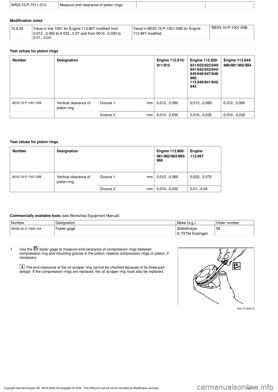
P03.10-2034-01
1
Use the
feeler gage to measure end clearance of compression rings between
compression ring and mounting groove in the piston; replace compression rings or piston, if
necessary.
The end clearance of the oil scraper ring cannot be checked because of its three-part
design. If the compression rings are replaced, the oil scraper ring must also be replaced.
Copyright DaimlerChrysler AG 20.05.2006 CD-Ausgabe G/10/04 . This WIS print-out will not be recorde
d by Modification services.
Page 1
Page 3741 of 4133
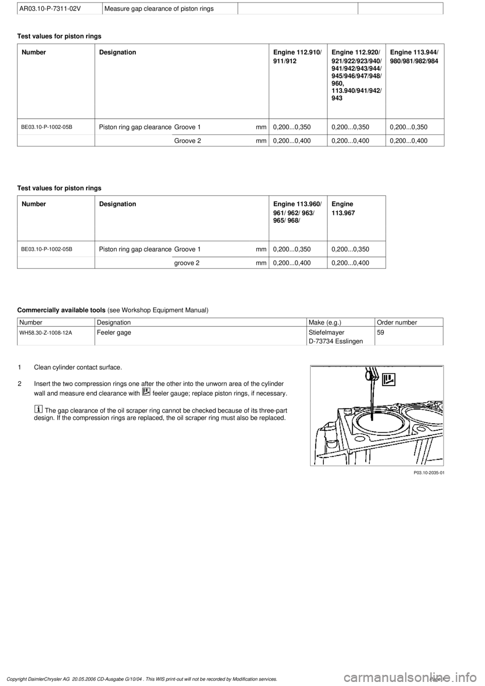
AR03.10-P-7311-02V
Measure gap clearance of piston rings
Test values for piston rings
Number
Designation
Engine 112.910/
911/912
Engine 112.920/
921/922/923/940/
941/942/943/944/
945/946/947/948/
960,
113.940/941/942/
943
Engine 113.944/
980/981/982/984
BE03.10-P-1002-05B
Piston ring gap clearance
Groove 1
mm
0,200...0,3500,200...0,3500,200...0,350
Groove 2
mm
0,200...0,4000,200...0,4000,200...0,400
Test values for piston rings
Number
Designation
Engine 113.960/
961/ 962/ 963/
965/ 968/
Engine
113.967
BE03.10-P-1002-05B
Piston ring gap clearance
Groove 1
mm
0,200...0,3500,200...0,350
groove 2
mm
0,200...0,4000,200...0,400
Commercially available tools
(see Workshop Equipment Manual)
Number
Designation
Make (e.g.)
Order number
WH58.30-Z-1008-12A
Feeler gage
Stiefelmayer
D-73734 Esslingen
59
P03.10-2035-01
1
Clean cylinder contact surface.
2
Insert the two compression rings one after the other into the unworn area of the cylinder
wall and measure end clearance with
feeler gauge; replace piston rings, if necessary.
The gap clearance of the oil scraper ring cannot be checked because of its three-part
design. If the compression rings are replaced, the oil scraper ring must also be replaced.
Copyright DaimlerChrysler AG 20.05.2006 CD-Ausgabe G/10/04 . This WIS print-out will not be recorde
d by Modification services.
Page 1
Page 3742 of 4133
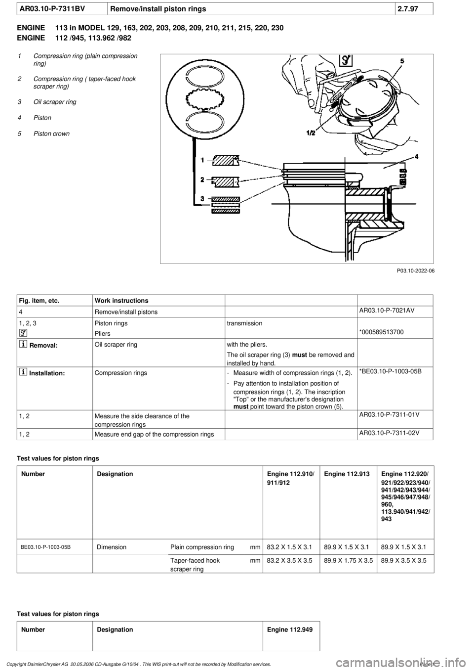
AR03.10-P-7311BV
Remove/install piston rings
2.7.97
ENGINE
113 in MODEL 129, 163, 202, 203, 208, 209, 210, 211, 215, 220, 230
ENGINE
112 /945, 113.962 /982
P03.10-2022-06
1
Compression ring (plain compression
ring)
2
Compression ring ( taper-faced hook
scraper ring)
3
Oil scraper ring
4
Piston
5
Piston crown
Fig. item, etc.
Work instructions
4
Remove/install pistons
AR03.10-P-7021AV
1, 2, 3
Piston rings
transmission
Pliers
*000589513700
Removal:
Oil scraper ring
with the pliers.
The oil scraper ring (3)
must be removed and
installed by hand.
Installation:
Compression rings
-
Measure width of compression rings (1, 2).
*BE03.10-P-1003-05B
-
Pay attention to installation position of
compression rings (1, 2). The inscription
"Top" or the manufacturer's designation
must
point toward the piston crown (5).
1, 2
Measure the side clearance of the
compression rings
AR03.10-P-7311-01V
1, 2
Measure end gap of the compression rings
AR03.10-P-7311-02V
Test values for piston rings
Number
Designation
Engine 112.910/
911/912
Engine 112.913
Engine 112.920/
921/922/923/940/
941/942/943/944/
945/946/947/948/
960,
113.940/941/942/
943
BE03.10-P-1003-05B
Dimension
Plain compression ring
mm
83.2 X 1.5 X 3.189.9 X 1.5 X 3.189.9 X 1.5 X 3.1
Taper-faced hook
scraper ring
mm
83.2 X 3.5 X 3.5
89.9 X 1.75 X 3.5
89.9 X 3.5 X 3.5
Test values for piston rings
Number
Designation
Engine 112.949
Copyright DaimlerChrysler AG 20.05.2006 CD-Ausgabe G/10/04 . This WIS print-out will not be recorde
d by Modification services.
Page 1