Page 770 of 2189

Electrical Troubleshoot:ng ('gg - 00 Models)
Troubleshooting Flowchart - Shift Control Solenoid Valve B (cont,dl
PCM CONNECTOR A {25PI
LGl (BRN/BLK)
IBRN/BLKI LG2IBRN/BLK)
Wire side of temale terminals
Wire sid€ ot female terminals
FCM CONNECTORS
SHIFT @NTROL SOENOID VALVEA/A ASSEMBLY CONNECTOR (2PI
.-_
1)2-.T-
I sn e tcanlwxrt
(o
YI
Terminal side oI male terminals
Check for continuity between the820 terminal and body ground,and between the 822 terminaland body ground.
Ropair opan in the wirgsb.twocn the 820 rnd 822 te.mi,n.ls and ground lG10t), and..p.ir poor ground lG10t).
Check Shift Control Sol.noidVrlve B tor a Short Ci.cuit:1. Disconnect the 2P connectorfrom the shift control solenoidvalve A/B assembly.2. Check for continuity betweenthe D2 and 820 or 822 termi-nals.
Repair 3hort to ground in tho wirebotw.en tha 02 torminsl and theshift com.ol rolonoid v.lv. B.
Meaiuro Shift Cont.ol SolonoidVrlve B Raailtrnca at the SolonoidConn€c,toa:Messure the r€sistance belweenthe No. 2 terminal of the 6hiftcontrol solenoid valve A/Bassembly connector and bodyground.
R.pl.co th. 3hift control lolenoidv!lv. A/8.lsombly.ls the resistance 12 - 25 O?
Chack for open in the wi.ebetwoon th€ D2 termin.l and the3hift control lolanoid valv6 8.
B (25P1 - llDt
From page'14-91
SH B (GRN/WHTI
\
14-92
Page 776 of 2189
Electrical Troubleshooting ('99 - 00 Modelsl
Troubleshooting Flowchart - Linear Solenoid (cont'dl
Check Linea. Solenoid tor aShort Ci.cuit:Check for continuity between thebody ground and the 88 terminaland B17 terminal individually.
PCM CONNECTOR A {25PI
Wire side of female terminals
From page 14 97
Repair shon in the wir6 betweenth€ 88 and 817 terminals and thelin€ar solenoid,
Measure Linear SolenoidResistance:1. Connect the linear solenoidconnector,2. Meas u re the resistancebetween the Bg and 817 termtnals,
Repair loose te.minal or open inthe wire botwoen the 88 .nd Bl7t.rmin.b end the linoar 3olenoid.
ls the resistance approx. 5.0 O?
Check for loose terminal tit in thePCM conn€ctors, lf necessary,substitut6 a known-good PCMand recheck.
LSAM (WHTI
14-98
Page 780 of 2189

Electrical Troubleshooting ('99 - 00 Models)
Troubleshooting Flowchart - E Indicator Light Does Not Come On
FCM CONNECTOR B (25P}
LGl {8RN/ALKI{BRN/8LK}
Wire side ol temale terminals
LGl IBNN/BLK} LG2 {BRN/BLK)
i2t5 6q
910t7
LG2
o) (o
The Pll indicator light does notcome on when the ignitionswitch is fi.st turned ON (ll). lltshould come on for about twoseconda.l
Check the Service Check Con-nector:Make sure the special tool (SCS
Service Connector) is not connect-ed to the service check connector?
ls the specialtool {SCS ServiceConnector) is not connected tothe seNice check connector.
Disconnect the special tool fromthe service check connector andr6check.
Check the Dll lndicator LightiShift to d position.
Check for loose terminal fit in thePCM connecto13. It necessary.sub3titute a known-good PCMand recheck.
Does the @ indicator lightcome on?
Check the Ground Circuit:1. Turn the ignition switch OFF.2. Disconnect the B (25P) con-nector from the PCM.3. Check for continuity betweenthe 820 terminal and bodyground, and between the 822terminal and body ground.
Repair open in the wiresbetween the B20 rnd 822 termi-nals and ground (G101), andrep.ir poor ground (G1011.
Measure Power Supply CircuitVoltage:1. Turn the ignition switch ON {ll}.2. Measure the voltage betweenterminals B1 and 822 andbetween terminals Bg and820.
Repair open or short in the wi.obetween th6 81 and/or 89 termi-nals and the PGM-FI main relav,and between th€ PGM-FI mainr€ley rnd the under-hood tus€/relay box.
To page 14''103
14-102
Page 817 of 2189

Valve Body
2.
Repair
NOTE: This repair is only necessary if one or more of
the valves in a valve body do not slide smoothly in their
bores. You may use this procedure to free the valves in
the valve bodies.
1. Soak a sheet of #600 abrasive paper in ATF for
about 30 minutes.
Carefully tap the valve body so the sticking valve
drops out of its bore.
CAUTION: lt may b€ necessary to use a small
screwdriver to pry the valve free. Be careful not to
scratch the bore whh the screwdriver.
Inspect the valve for any scuff marks. Use the ATF-
soaked #600 paper to polish off any burrs that are
on the valve, then wash the valve in solvent and dry
it with compressed a ir.
Roll up half a sheet of ATF-soaked paper, and insert
it in the valve bore of the sticking valve.
Twist the paper slightly, so that it unrolls and fits the
bore tightly, then polish the bore by twisting the
paper as you push it in and out.
CAUTION: The valve body is aluminum and doesn't
require much polishing to remove any burrs,
3.
4.
ATF-soaked#600 abrasive Paper
5.
7.
Remove the #600 paper and thoroughly wash the
entire valve body in solvent. then dry it with com-
pressed air.
Coat the valve with ATF, then drop ir into its bore.
It should drop to the bonom of the bore under its
own weight. lf not, repeat step 4, then retest.
VALVE BODY
Remove the valve. then thoroughly clean it and the
valve body with solvent. Dry all parts with com-
pressed air. then reassemble using ATF as a lubri
cant.
W
-M
14-139
Page 820 of 2189
Main Valve Body
Disassembly/lnspection/Reassembly
NOTE:
. Cleanall parts thoroughly in solvent or carburetor cleaner, and drywith compressed air. Blowoutall passages.. Replace the valve body as an assembly if any pans are worn or damaged.. Check all valves for free movement. lf anyfail toslidefreely, see Valve Body Repairon page,l4-139.. Coat all parts with ATF during assembly.
CAUTION: Do not use a magnet to removs tha check balls; it may magnetizo the balls.
CPB VALVEVALVE CAP CLIP
ORIFICE CONTROL VALVE
BALLS, 8
lST ACCUMULATOR CHOKE
MODULATORVALVE
RELIEF VALVEVALVE
MAIN VALVE EODYInspect for wear, scratchesand scoring.
SEBVO CONTROL VAL
I.2 SHIFT VALVE
14-142
VALVE CAP
Page 822 of 2189

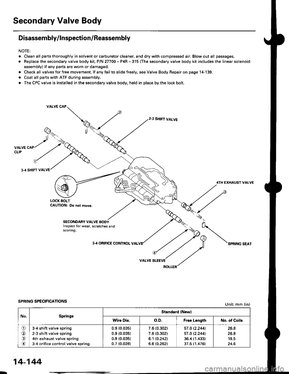
Secondary Valve Body
Disassembly/lnspection/Reassembly
NOTE:
. Cleanall parts thoroughly in solvent or carburetor cleaner. and drywith compressed air, Blowoutall passages.
. Replace the secondary valve body kit. P/N 27700 - P4R - 315 (The secondary valve body kit includes the linear solenoid
assembly) if any parts are worn or damaged.
. Checkall valves for free movement. lf anyfailto slide freely, seeValveBody Repairon page 14-139,
. Coat all parts with ATF during assembly.
. The CPC valve is installed in the secondary valve body, held in place by the lock bolt.
2.3 SHIFT VALVE
3.4 SHIFT VAL
.TH EXHAUST VALVE
LOCK BOLTCAUTION: Do not move.
SECONDARY VALVE BODYInspect for wear, scratches 6ndscoring.
3-'l ORIFICE CONTROL VAL
VALVE
SPRING SPECIFICATIONSUnit: mm (in)
No.SpringsStandard {New)
Wire Dia.o.D.Free LongthNo. of Coils
ora,.n
3-4 shift valve spring
2-3 sh ift valve spring
4th exhaust valve spring
3-4 orifice control valve spring
0.910.035)
0.9 {0.035)
0.9 {0.035)
0.7 {0.028)
7.6 (0.302)
7.6 (0.302)
6.1 10.2421
6.6 (0.262)
57 .O 12.2441
57 .O 12.2441
36.4 (1.433)
37.5 (1.476)
26.8
26.8
24.6
14-144
Page 823 of 2189

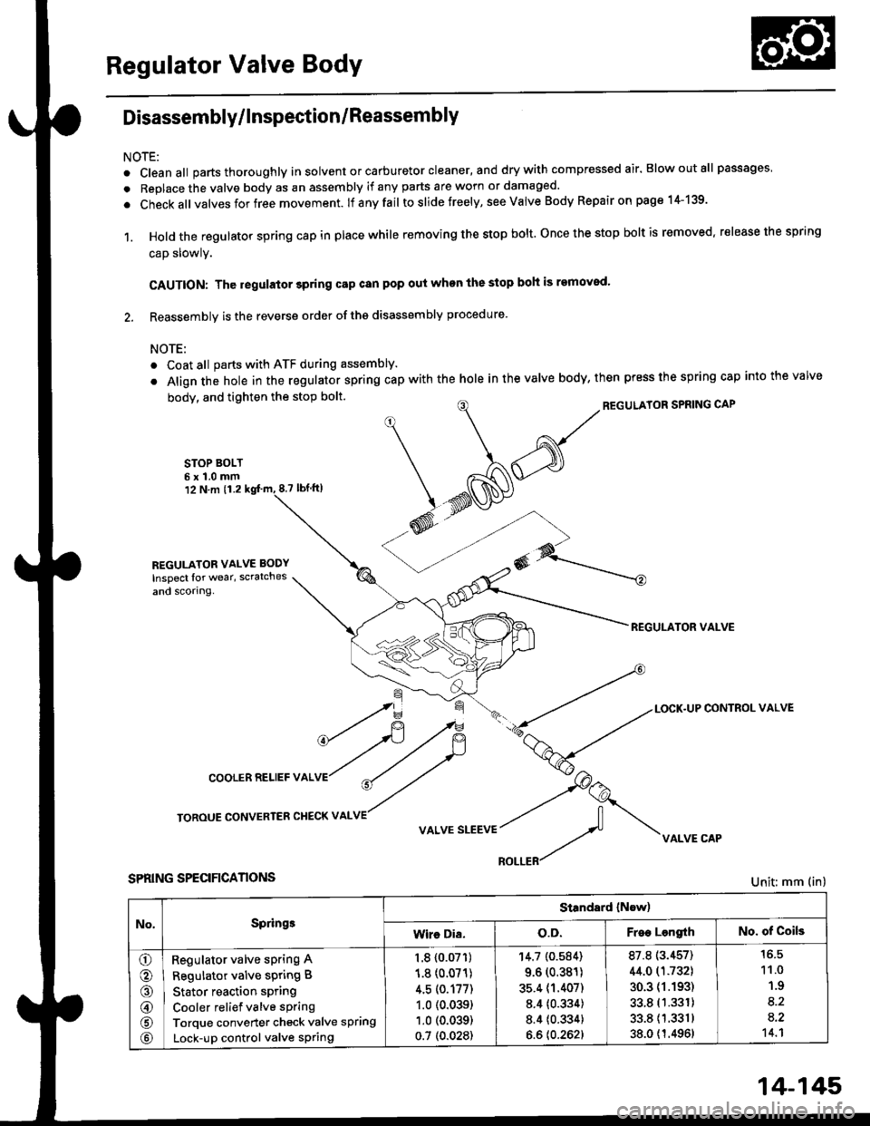
Regulator Valve Body
Disassembly/lnspection/Reassembly
NOTE:
. cleanall parts thoroughly in solvent or carburetor cleaner, and drywith compressed air. Blowoutall passages
. Replace the valve body as an assembly if any parts are worn or damaged.
. check allvalves for free movement. lf anyfail toslidetreely, see valve Body Repairon page 1+139.
1. Hold the regulator spring cap in place while removing the stop bolt. once the stop bolt is removed. release the spring
cap slowly.
CAUTION: The regulator 3pring cap can pop out when the stop boh is removod'
2. Reassembly is the reverse order ofths disassembly procedure.
NOTE:
o Coat all parts with ATF during assembly.
. Align the hole in the regulator spring cap with the hole in the valve body, then press the spring cap into the valve
body, and tighten the stop bolt.
STOP BOLT6x1.0mm12 N.m 11.28.7 tbf.lrl
^/^'ou*'oRsPRrNGcAP
*N@
REGULATOR VALVE
\=f -.-*
*fi /F { a-tLocK.uPcoNrRoLvALVE
cooLERRELlEFvALVr"r?
ry
roRouE coNvERrER cHEcKv ^LvE//
v ^r* "r**::f vi{LvE cAp
SPRING SPECIFICANONS
REGULATOR VALVE BODY
Inspect lor wear, scratches
and scorlng.
Unit: mm (in)
No,Springe
Standard (Now)
Wire Dia.o.D.Free LengrthNo. of Coils
o
o
@
@
@
Regulator valve sPring A
Regulator valve spring B
Stator reaction spring
Cooler relief valve spring
Torque converter check valve spring
Lock-up control valve sPring
1.8 {0.07'�r)
1.8 (0.071)
4.5 (0.177)
1.0 (0.039)
1.0 (0.039)
0.7 (0.028)
'r4.7 (0.584)
9.6 (0.381)
35.4 (1.407)
8.4 {0.334)
8.4 {0.334}
6.6 {0.262}
87.8 (3.457)
44.0 (1.732)
30.3 (1.193)
33.8 (1.331)
33.811.3311
38.0 {1.4961
11.0
1.9
8.2
a.2't 4.1
14-145
Page 825 of 2189
Lock-up Valve BodY
Disassembly/lnspection/Reassembly
NOTE:
. Clean all pans thoroughly in solvent or carburetor cleaner' and dry with compressed air' Blow out all passages'
a Replace the valve body as an assembly if any parts are worn or d€maged'
. Checkall valves for free movement ttanytaitio stlae freely' see Valve Body Repairon page 14-'139'
. Coat all parts with ATF during assembly
LOCK.UP VALVE BODY
Inspect for wear, scratchesand sconng.
VALVE CAP
LOCK-UP TIMING VAL
SPRING SPECIFICATIONSUnit: mm (in)
73.1 t2.902J
ao.7 13.'17717.6 (0.302)
8.1 (0.319)Lock-up shift valve sPrang
Lock-up timing valve sPrlng
14-147