Page 478 of 2189

tAlternator (ALT) FR Signal ('99 - 00 Models except Dl6Y5 engine with M/T)
This signals the ECM/PCM when the Alternator {ALT) is chargingECM/PCM CONNECTORS
Wire side of female terminals
ECM/PCM CONNECTOR C (31P}
lt
lP
ALT CONNECTORS IClO4I
JUMPER
JUMpER WlnE
WIRE
Wire side of female termlnals
ECM/PCM CONNECTOR C (31PI
3P*NO
Check lor an op€n in the wire (ALT
F line,:1. Turn the agnition switch OFF
2. Disconnect the negative bat-
tery cable {rom the battery.
3. Disconnect the ECM/PCM con'
nector C (31P).
4. Disconnect the 4P (3P)* con'
nector from the ALT.
5. Connect the ALT 4P (3P)* con-
nector terminal No 4 (No. 1)*
to bodY ground with a iumper
6. Check lor continuity between
body ground and ECM/PCM
connector terminal C5
--?--1l2l|�#i3l.l
otriJrwxrr (V)
neor Y
lnsoeclion oI ALT FB Signal.
Check {or a short in the wire {ALT
F line):1. Disconnect the 4P (3P)+ con
nector from the ALT
2. Turn the ignition switch ON (ll)
3. Measurc voltage between EcM/
PCM connector terminals C5
and 820.Check tor a short in the wirc (ALt
F line):1. Turn the ignition switch OFF
2. Disconnect the negative bat_
tery cable from the baRery'
3. Disconnect the ECM/PCM con'
nector C (31P).
4. Check for continuity between
body ground and ECM/PCM
connector terminal C5
ls there aPProx. 5 V?
Check the operation otthe ALT:
1. Turn the ignition switch OFF.
2- Reconnect the ALT 4P (3P)*
connector to the ALT
3. Start the engine. Hold the
engine at 3,000 rpm wrth no
load {in Park or neutrali until
the radiator fan comes on,
then let it idle.
4- Measure voltage between ECM/
PCM connector terminals C5
and 820.
Repair short in the wire between
the EcM/PCM {C5l and the ALT.
Substitute a known-good ECM/
PCM and rechock. lf P.esc.ibedvoltage is now availabl€, ieplace
tho original ECM/PCM
Does the voltage decrease when
headlights and rear delogger are
turned on?
ALT FF signal is OK.
Repair oPen wire betwoen t|lo
ECM,/PCM {C5) and the ALT.
ALT F (WHT/RED)
Wire side of temale terminals
*: Canada model
Wire side of female termrnals
Page 482 of 2189
t
(From page 11 212)
Check lor a 3hort in the PSP
switch:1. Turn the ignition switch OFF.
2. Disconnect the 2P connector
from the PSP switch.
3. Turn the ignition switch ON (ll)
4. Measure voltage between
ECM/PCM connector termi-
nals Ag and C16.
Check tor a short in the wiro {PSP
SW linel:'1. Turn the ignition switch OFF.
2. Disconnect the ECM/PCM con
nector C (31P).
3. Check lor continuity between
body ground and ECM/PCM
connector terminal C16.
ls there battery vohage?
Repair ahort in the wire between
the ECM/PCM (C16) and th6 PsP
switch.
Substitute a known_good ECM/
PCM end rechock. lf Prescribedvoltage b now avsilable. rePlace
the original ECM/PCM.
ECM/PCM CONNECTORS
Wire side of temale terminals
'l
12a6189t0
tl12131415161718
232125a30
oPSP SW (GRNI
1-213
Page 485 of 2189

ldle Control System
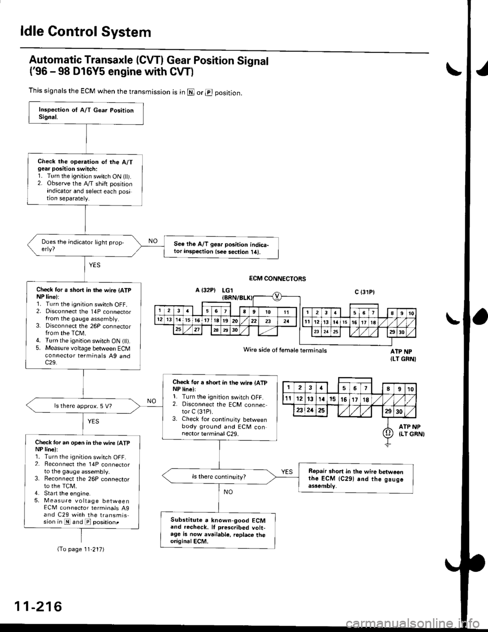
Automatic Transaxle (CVTI Gear Position Signal
('96 -98 D16Y5 engine with CW)
ATP NP{LT GRNI
INP
GBN)
This signals the ECM when the transmission is in @ or @ position.
Check the operation oI the A/Tgear position switch:1. Turn the ignition switch ON flt).2. Observe the A/T shift positionindicator and select each position separately.
See lhe A/T gear position indica-tor insp€ction {see sec{ion l/tl.
Check tor a short in the wir6 (ATpNP line):1. Turn the ignition switch OFF.2. Disconnect the 14P connectorIrom the gauge assembly.3. Disconnect the 26P connectorfrom the TCM.4. Turn the ignition switch ON fll).5. Measure voltage between ECMconnector terminals A9 andc29.
Check for a short in the wire lATpNP linell1. Turn the ignition switch OFF.2. Disconnect the ECM connector C (31P).
3. Check for continuity betweenbody ground and ECM connector terminal C29.
ls there approx. 5 V?
Check for an open in the wire lATpNP lina):1. Turn the ignition switch OFF_2. Beconnect the 14P connectorto the gauge assembly.3. Reconnect the 26P connectorto the TCM.4. Sta rt the engine.5. Measure voltage betweenECM connector terminals A9and C29 with the transmission in E and E posationt
Repair short in the wire betweenthe ECM {C291 and the gaugeassemblv,
Substitute a known-good ECMand recheck. lf prescribed volt-age is now avrilable, replace theo.iginalECM.
Wire side ot female terminals
2457I910
t112131a15151718
2321252930
ATP(LT io
(To page 11'217)
11-216
Page 487 of 2189

ldle Control System
{
(
a
Clutch Switch Signal (Dl6YS engine with M/Tl
This signals the ECM when the clutch is engaged.
A {32P}
ECM CONNECTORS
LGl (BRN/BLK)
\-
cLsw(RED}
Inrpaction ot dutch rwitch signal.
Check for on opon in the wiro(CLSW linel:'!. Turn the ignition switch ON (ll).2. Measure voltage betweon ECt!4connector terminals C29 andA9.
Ch.ck tho clutch switch:1. Turn the ignition switch OFF.2. Disconnect the 2P connectorfrom the clutch switch.3. Turn the ignition switch ON (ll).4. Measure voltage b€tween ECMconnector terminals C29 and
ls thare approx. 5 V?
ls there approx. 5 V?
Check for a short in th6 wire(CLSW line)l1. Turn the ignition swirch OFF.2. Disconnect the ECM connector C (31P)trom the ECM.3. Check lor continuity betweenECM connector terminal C29and body ground.
Chcck for an open in thg wire{CLSW linel:1. Depress the clutch pedal.2. Moasure voltage between ECMconnector torminals C29 andA9.
Repair short in the wirc betweentho ECM {C291 and tho clurchswitch.
Sub3titutg a known-good ECMand rechock, It p.e3cribed vohagoi! now available, roplace the orig-inal ECM.
Wire side of female terminals
26189101l12t3'tat5l617l822
o
(To page 11-219)
11-218
!
Page 488 of 2189
{From page 11-218)
Check lho clutch switch:
1. Turn the ignition switch OFF.
2. Disconnect the 2P connector
from the clutch switch.
3. Check lor continuity between
the clutch switch connector
terminals No. 1 and No.2 with
the clutch pedal depressed
ls voltage less than 1.0 V?
- Adiu3t the clutch swiich.- Reolace lhe clutch switch.
Check for an open in tha wiie:
1. Turn the ignition switch ON lll)
2. Measure voltage between the
clutch switch connector terml'nal No. 1 and body ground with
the clutch pedal depressed.
Repair op€n in the wire betwoen
the EcM (C291 and thc clutch
swilch.ls there approx. 5 V?
Repair open in BLK wire betweenthe clutch switch and Gircl.
Clutch switch signal is OK.
CLUTCH SWITCH 2P CONNECTOR
j-t -
Terminal side of male
termrnals
CLUTCH SWITCH 2P CONNECTOR {C41',
-f--r
I'l'l-l_-
clsw 1;1tREDr Y
Wire 6ide of lemaleterminals
I
lr,
11-219
Page 507 of 2189

Fuel Supply System
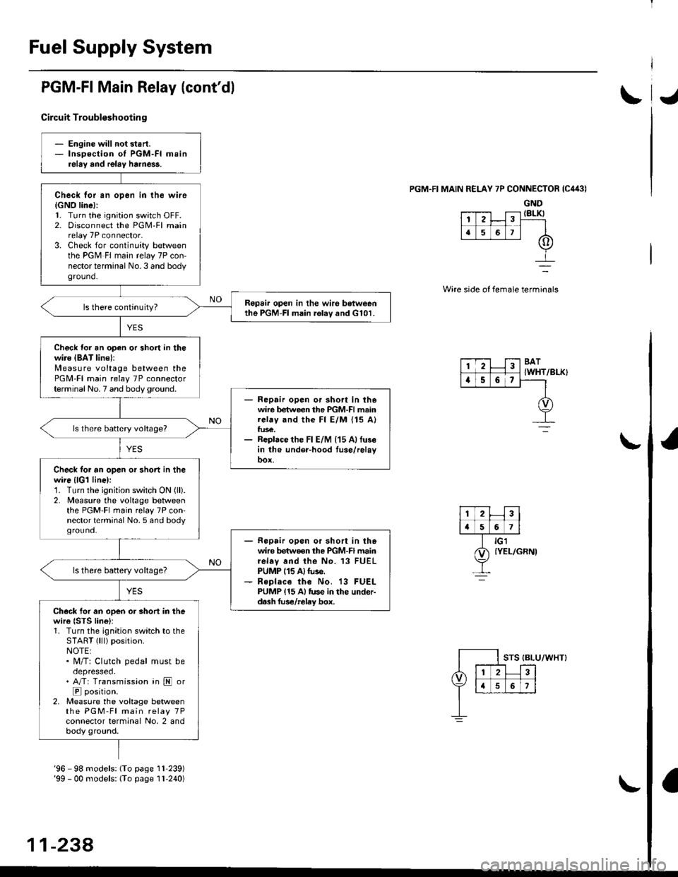
PGM-FI Main Relay (cont'dl
Circuit Troubleshootin g
PGM.FI MAIN RELAY 7P CONNECTOR {C443)
GND{8LK)
Wire side of female terminals
/BLK}
- Engine will not start.- lnsoection of PGM-FI mainrelay and relay harne$.
Check for an open in the wire{GNO line}:l. Turn the ignition switch OFF.2. Disconnect the PGM-Fl mainrelay 7P connector.3. Check for continuity betweenthe PGM Fl main relay 7P con-nector terminal No.3 and bodyground.
Ropai. open in the wir€ betweenthe PGM-FI main .elav and G101.
Check for an open or short in thewire {BAT lin€}:N4easure voltage between thePGM-FI main relay 7P connectorterminal No. 7 and body ground.- Repair open or sho.t in thewire between the PGM-FI mainrelay and the Fl E/M {15 A}fus€.- Replace the Fl E/M (15 Allu3ein the under-hood fuse/relayoox.
ls lhere battery voltage?
Check tor an open or short in thewire {lGl line):1. Turn the ignition switch ON (ll).
2. Measure the voltage betweenthe PGM-Fl main relay 7P con'nector terminal No. 5 and bodyground.- Repair open or short in thewire betwoen the PGM-FI mainrelav and the No. 13 FUELPUMP (15 A)tuse.- R€place the No. 13 FUELPUMP {15 A} tus€ in the under-d.sh fus€/relay box.
ls there battery voltage?
Ch.ck for an open or short in thewire {STS lino}r1. Turn the ignition switch to theSTART (lll) position.NOTE:. M/T: Clutch pedal must beoepresseo.. A/T: Transmission in E or
E position.2, Measure the voltage betweenthe PGM-Fl main relay 7Pconnector terminal No, 2 andbody ground.
12
[,a567
123BAT
{WHTa56,
'96 98 models: (To page 1l 239)'99 - 00 models: (To page I l-240)
11-238,
Page 529 of 2189

Emission Control System
Exhaust Gas Recirculation (EGR) System (Dl6Y5 engine with CW) (cont'dl
tJ
(From page 11-259)EGR CONTROL SOLENOIDVALVE 2P CONNECTOR {C142}
Wire sideof lemaleterminals
ECMCONNECTORa t32Pl
Chock lor an open in the wire (E
SOL linsl:1. Turn the ignition switch OFF.2. Disconnect the 2P connectorIrom the EGR control solenoid
3. Disconnect the ECN4/PCM con-nector A (32P) (B (25P))* fromthe EcM/PCM.4. Check tor continuity betweenECM/PCl, connector terminal47 (86)* and the EGR controlsolenoid valve 2P connectorterminal No.2.
Repair opon in th. wir. bstwocntha EGR control 3ol€noid valvoand tho ECM/PCM (A7 186l'1.
ls there continuity?
Check for . rhort in the wire(ESOL linel:Check for continuity between theEGR controlsolenoid valve 2P con-nector terminal No. 2 and bodyground,
R.p.ir ahort in tha wi.c b.twecnthe EGR control iolonoid vllyeand th. ECM/FCM {A7 (46}rl.
Check for an opon in the wiroIGND linel:Check for continuity between theEGR controlsolenoid vaive 2P con-nector terminal No. I and bodyground,
Rcpai. op€n in the wir6 b6'twoenthe EGR control rol.noid valveand G101.
Sub3titule a known-good ECM/PCM and rechock. lf symptom/indication goes away, replac€the original ECM/PCM.
ESOL
IRED)
ESOLIRED)
Wire sideof femaleterminals--_-]
I
EGR CONTROL SOLENOIDVALVE 2P CONNECTOR ICl'2}
Wire sideof femaleilterminals
ECMCONNECTORB l25P)ESOL(REDI
Wire sideof femalerermtnats
*: '99 - 00 models
11-260
Page 533 of 2189

Emission Gontrol System
Exhaust Gas Recirculation System (Dl6Y5 engine with M/Tl (cont'dl
lFrom page 11 263)EGR VALVE6P CONNECTOR {C144}
J
Wire sideof femaletermtnals
J
Check lor an op€n in the wire (E-
EGR line):1. Turn the ignition switch OFF.2. Disconnect the ECM connector,A (32P)trom the ECM.3. Check lor continuity betweenECM connector terminal A7and the EGR valve 6P connec-torterminal No. 6.
Repair open in the wiro botweenthe EGR valv6.nd th€ ECM {A71.
Check tor a short in the wire {E-EGR lin6l:Check for continuity betweenECM connector terminal A7 andbody ground.
Reoair shorl in tho wiro belwe€nthe EGn vake rnd the ECM lA7l.ls there continuity?
Check fo. an open in tho wiro
IGND line):Check for continuity between theEGR valve 6P connector terminalNo.4 and body ground.
R6pai. open in th€ wir. betweenth6 EGF control solenoid v6lveand G101.
Substitute 8 known-good ECMand recheck. It symptom/indica-tion goes away, roplace the origi-nalECM.
CONNECTORA l32P)
2
a
I G101
Q) raur
-264