1997 HONDA CIVIC Body repair
[x] Cancel search: Body repairPage 461 of 2189
ldle Control System
ldle ControlSystem
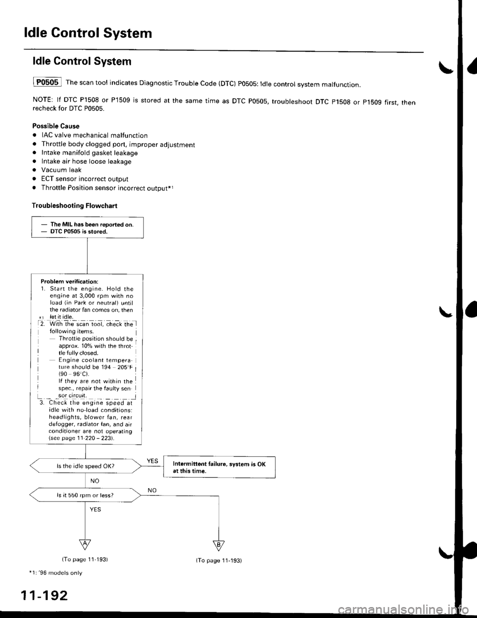
lF0505 l Th" """n tool indicates Diagnostic Trouble Code (DTC) PO5O5: tdte controt system malfunction.
NOTE: lf DTC P1508 or P1509 is stored at the same time as DTC P0505, troubleshoot DTC p1508 or p1bog first. thenrecheck for DTC P0505.
Possible Cause
. IAC valve mechanical malfunction
. Throttle body clogged pon, improper adjustment. Intake manifold gasket leakage
. Intake air hose loose leakage
. Vacu um leak
. ECT sensor incorrect output
. Throttle Position sensor incorrect output*r
Troubleshooting Flowchart
The MIL has been reoorted on.DTC P0505 is stored.
Problem verification:1. Start the engine. Hold theeng;ne at 3,000 rpm with noload (jn Park or neutral) untilthe radiator fan comes on, then*r let it idle.t2. with rhe scan toot, ct'eit Ge l
Throttle position should beapprox. 10% with the throttle fully closed.E ngine coolant tempera-ture should be 194 205'F(90 96.Ci.lf they are not within thespec., repair the faulty sen
L._ _9oI9[cr]41 l3. Chec& the engine speed atidle with no-load cond;tionsiheadlights, blower fan, reardefogger, radiator fan, and airconditioner are not operating\see page l1-22O - 223).
Intermittent tailure, system is OKat this time.ls the idle speed OK?
ls it 550 rpm or less?
(To page 11,193)
*1r'96 models only
11-192
(To page ll-193)
Page 462 of 2189
I
L
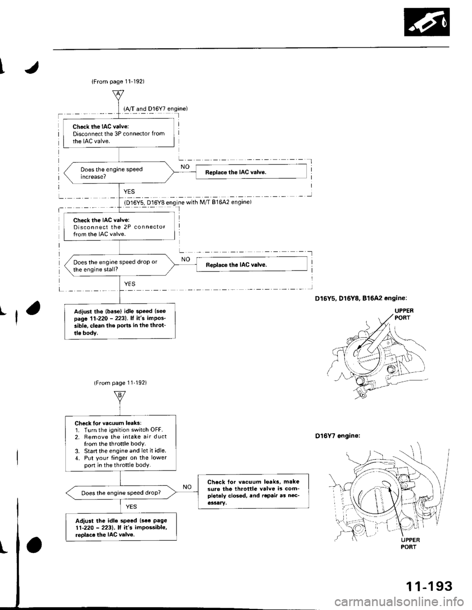
1D16Y5, D16Y8 engine with M/T 81642 engine)I
D16Y7 engine:
{From page 11-192)
Check the IAC valve:Disconnect the 3P connector from
the IAC valve.
Check the IAC valve:Disconnect the 2P connectorfrom the IAC valve.
Does the engine speed drop or
the engine stall?
Adiust the {base} idle speod (see
page 11-220 - 2231.It it's impos-
aible, clean the ports in lhe throt'
tle bodv,
(From page 11-192i
Check Ior vacuum leaks:1. Turn the ignition switch OFF.2. Remove the intake air ductfrom the throttle body.
3. Start the engine and let it idle.
4. Put your finger on the lowerpon in the th.ottle body.
Ch€ck tor vecuum loaks, m.kesure the throttle valve is com_pletaly closed, end repair as nec-Does the engine speed droP?
Adiust the idle speed (see page
11-220 - 2231. lf it's impossible,
reolace the IAC velve.UPPERPORT
1 1-1 93
Page 465 of 2189
![HONDA CIVIC 1997 6.G Workshop Manual ldle Gontrol System
ldle Air Control (lAG) Valve (99 - 00 Dl6Y8 engine with M/T, Bt6A2 enginel
[Fl50g l ]h" scan tool indicates Diagnostic Trouble Code (DTC) P1508: A problem in the ldle Air Controt HONDA CIVIC 1997 6.G Workshop Manual ldle Gontrol System
ldle Air Control (lAG) Valve (99 - 00 Dl6Y8 engine with M/T, Bt6A2 enginel
[Fl50g l ]h" scan tool indicates Diagnostic Trouble Code (DTC) P1508: A problem in the ldle Air Controt](/manual-img/13/6068/w960_6068-464.png)
ldle Gontrol System
ldle Air Control (lAG) Valve ('99 - 00 Dl6Y8 engine with M/T, Bt6A2 enginel
[Fl50g l ]h" scan tool indicates Diagnostic Trouble Code (DTC) P1508: A problem in the ldle Air Controt AC) vatve- CtrCUtt.
The IAC Valve changes the amount of air bypassing the throttle body in response to a current signal from the ECM inorder to maintain the proper idle speed.
IAC VALVE 2P CONNECTOR IC138'
la rcprI - {YEL/8LKI 2t--d,
Y-=
Wire side ot female terminals
Wire side of lemale terminals
VALVE
The MIL has boon r€oorted on.DTC P1508 is srored.
Probl6m verification:1. Do the ECM/PCM Reset Pro-cedure.2. Start the engine, and warm itup to normal operating lem-perature.
Intermittent tailure, system is OKat this timg. Check to. poor con-noctions or loose wires at C138{lAC valvel and ECM.
ls DTC P1508 indicated?
Ch6ck for an open in the wir€{lGPl lino}:1. Turn the ignition switch OFF.2. Disconnect the IAC valve 2Pconnector.3. Turn the ignition switch ON (ll).
4. Measure voltage between bodyground and the IAC valve 2Pconneclor termina I No.2,
Repair opon in the wire bgtwoenIAC valve and PGM-Fl main relay.
Check tof an open or short in thewire {IACV line}l1. Turn the ignition switch OFFand reconnect the IAC valve
2. Disconnect the ECM connectorB {25P).3. Turn the ignition switch ON (ll).
4. Measure voltage betweenbody ground and ECM conn€ctor terminal 823.
(To page 11-197)
1 1-1 96
Page 467 of 2189
ldle Control System
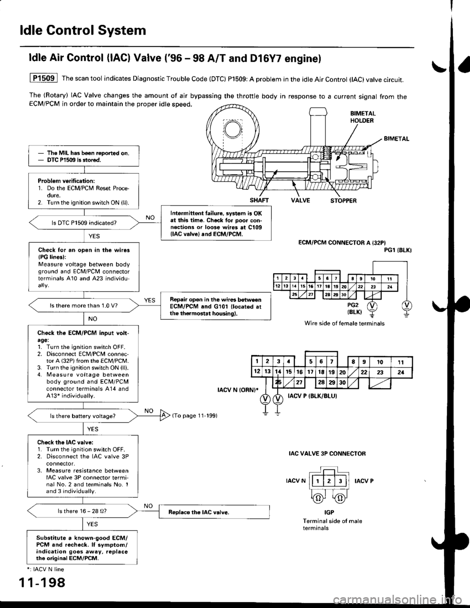
ldle Air Control (lAC) Valve ('96 - 98 A/T and Dl6Y7 enginel
The (Rotary) IAC Valve changes the amount of air bypassing the throttle body in response to a current signal from theECM/PCM in order to maintain the proper idle speed,
BIMETAL
VALVESTOPPER
1P1509 Thescantool indicates Diagnostic Trouble Code (DTC) P1509: A problem in the idle Air Control (tAC)valve circuit.
ECM/PCM CONNECTOR A I32PIPGl IBLKI
IAC VALVE 3P CONNECIOR
IACV NIACV P
IGP
Terminal side of maleterminals
*: IACV N line
1 1-198
The MIL has b€€n roported on.DTC P1509 is stored.
Problem verification:1. Do the ECM/PCM Reset Proce-oure.2. Turn the ignition switch ON (ll).
Intermittent failura, systom ia OKat this time. Check tor poo. con-noctions or loose wires at C109llAC valve) and ECM/PCM.
ls DTC P1509 indicated?
Check for an opon in the wirer{PG lines):Measure voltage between bodvground and ECM/PCII connectorterminals A10 and A23 individu
Repair op€n in the wires betwoenECM/PCM and G101 llocated attho thermostat housing).
ls there more than 1.0 V?
Chock th€ ECM/PCM inpui volt-agel1. Turn the ignition switch OFF.2. Disconnect ECM/PCM connec-tor A (32P)from the ECM/PCM.3. Turn the ignition switch ON (ll).4. Measu re voltage betweenbody ground and ECM/PCMconnector terminals A14 andA13* individually.
Ch6ck th6 IAC valve:1. Turn the ignition switch OFF.2. Disconnect the IAC valve 3Pconnector,3, Measure resistance betweenIAC valve 3P connector termi-nal No.2 and terminals No. 1and 3 individually.
ls there 16 - 28 g?
Substitute a known-good ECM/PCM and recheck. lf symptom/indication goos away, replaceth€ origin.l ECM/PCM.
SHAFT
rAcv N loRNl*
(To page 11-199)
Wire side of lemale terminals
123a56El011
121314r5161718t9202:22321
272AA30
IACV P {BLK/BLUI
Page 470 of 2189
I
I
L
IACV N(oRN)*IACV P{BLK/BLU'
ECM/PCMCONNECTON B (25PI
IACV N(oRNt.
Wire side of female terminals
IAC VALVE 3P CONNECTOR
IACV NIACV P
IACV P
IBLK/BLUI
IGP
Terminal side of male
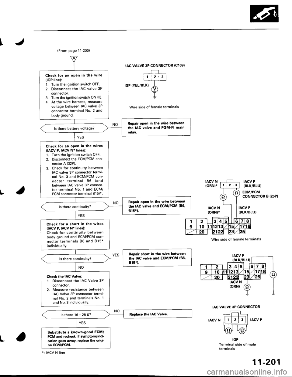
(From page 11 200)
IAC VALVE 3P CONNECTOR {C1O9I
IGP (YEL/BLK)
Wire side of female terminals
Check toi an open in thg wire
{lGP line):1. Turn the ignition switch OFF.
2. Disconnect the IAC valve 3P
connector.3. Turn the ignition switch ON (ll)
4, At the wire harness, measure
voltage between IAC valve 3P
connector terminal No. 2 and
body gro!nd.
Repair open in the wire between
the IAC valve and PGM-FI main
reraY.
Check for an open in the wires
IIACV P. IACV N' lines):
1. Turn the ignition switch OFF.
2. Disconnect the ECM/PCM con-
nector A (32P).
3. Check lor continuity between
IAC valve 3P connector termi'nal No. 3 and ECM/PCM con-necto r terminal B6 (and
beNveen IAC valve 3P connector terminal No. 1 and ECM/PCM connector terminal 815)*.
Repair open in the wiro ltstwcen
the IAC valvo and €CM/PCM (86,
815'1.
Check for a shon in the wires(IACV P, lACv N* linesl:Check for continuity between
body ground and ECM/PCM con-
nector terminals 86 and 815*
individually.
Reoair short in the wiro Mweonthe lac valve end ECM/FCM (86,
815*).ls there continuity?
Check the IAC valv€:l. Disconnect the IAC Valve 3P
connector,2. Measure resislance betweenIAC Valve 3P connector termi
nal No. 2 and terminals No 1and No.3 individually
ls there 16 - 28 O?
Substituta . known-good ECM/
PCM and rochcdc f 3ymptom/indication go€a away, r€dace the original ECM/Pqvl.
"r IACV N line
N
11-201
Page 474 of 2189
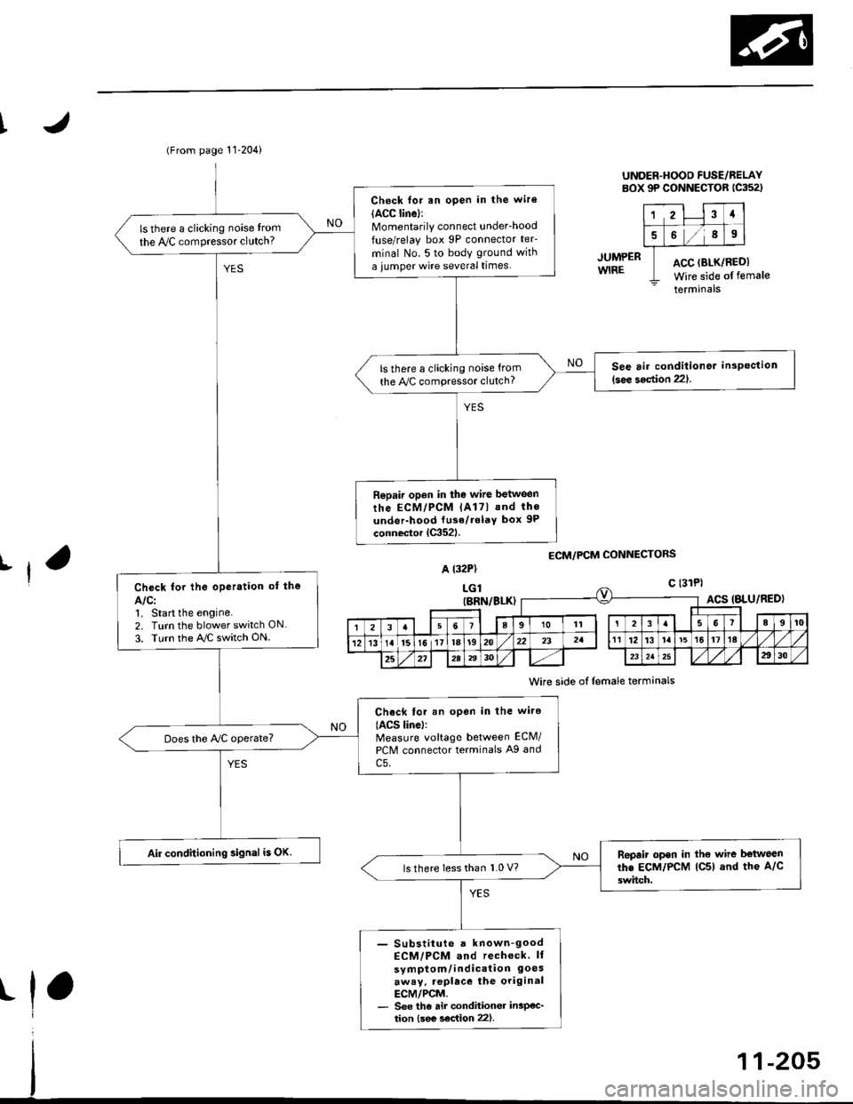
(From page 11-204)
Check for an open in the wir€(ACC linel:Momentarily connect underhood
fuse/relay box 9P connector teF
minal No. 5 to body ground with
a iumper wire several times.
ls there a clicking noise from
the IVC compressor clutch?
See air conditionor inspection(see 3oction 221.ls there a clicking noise from
the Py'C compressor clutch?
Repair open in the wire between
rhe ECM/PCM lAl7l and th6
under-hood fu3e/rolaY box 9P
connector lC352l.
Check for the oPeration of the
Alcl1. Start the engine.2. Turn the blower switch ON
3. Turn the AJC switch ON.
Chock tor an open in the wire
IACS linel:Measure voltage between ECM/
PCM connector terminals A9 and
c5.
Does the Ay'C operate?
Air conditioning signal is OK.Repair open in the wire b€tweenthe EcM/PcM lC5) and the A/c
3witch.ls there less than 1.0 V?
- Substiiute a known-goodECM/PCM and recheck ll
symptom/indication 9oesaway, .oplace the originalECM/PCM.- See the air condhioner insP€c_tion {see s€c{ion 22).
UNDER.HOOD FUSE/BELAYBOX 9P CONNECTOR 1C352)
12Ia
589
ACC (BLK/RI
Wire side ofACC (BLK/REDI
Wire side of female
terminals
JUMPERWIRE
ECM/PCM CONNECTORSrfA t32P)
LGlc {31Pl
t
(BRN/BLK)ACS IBLU/RED)
I23a9101t3I89t0
121315l611la1920232att12't3la't5t617ta
25272A2930232a2930
Wire side of lemale terminals
Page 476 of 2189

I
JUMP€RWIRE
UNDER-HOOO FUSE/RELAYsox 9P coNNEcroR lca52l
123a
5689
ACC (8LK/REDI
Wire side ofterminals
ECM/PCM CONNECTORS
A (32P1
female
Wire side of {emale terminals
(From page 11-206)
Check for an open in the wite
IACC lino):Momentarily connect under_hood
luse/relay box 9P connector teF
minal No. 5 to body ground with
a jumper wire several times.
ls there a clicking noise from
the Iy'C compressor clutch?
S6e air conditioner insPoction
l3oa section 221ls there a clicking noise lrom
the ly'C compressor clutch?
Ropair open in tho wilo betwg€n
the ECM/PCM lA17) and the A/C
clutch rolay.
Chock for the oporation of lho
AIC:1, Start the engine.
2. Turn the blower switch ON
3. Turn the ray'C switch ON.
Check lor an open in the wiro(ACS lino):Measure voltage between ECM/
PCM connector terminals A27
and 820.
Does the Iy'C operate?
Air conditioning signal is OK.Repair op6n in the wiro bctwoon
lhe ECM/PCM lA27l and tho A/C
3witch.ls voltage lessthan 1.0 V?
- Sub6iitut€ r known€ood ECtt /PCM and rccheck. ll sYmP-
tom/indication 9oe3.waY,replaca the original ECM/PCM- See the ai. condhionGr in3p€c-tion lsee soc{ion 221.
11-207
Page 477 of 2189

ldle Control System
Alternator (ALTI FR Signal {'96 - 98 Models,'99 - 00 Dl6y5 engine with M/Tl
ECM/PCM CONNECTORS
a {32P)
LGl(BRN/BLK)
Wire side of female terminals
ALT CONNECTORS IC1O4I
JUMPER
JUMPER WIRE
WIRE
Wire side of female terminals
ALT F{WHT/REO)
This signals the ECM/PCM when the Alternator (ALT) is charging.
Inspoction of ALT FR Signal.
Check tor a short in tfte wire (ALTF linel:1. oisconnect the 4P (3P)* con-nector from the ALT.2. Turn the ignition switch ON (ll).3. M easu re voltage betweenECM/PCM connector terminals C17 and A9.Check lor a sho.t in the wire {ALTF line):r. I urn rne tgn|lton swtlch ul-f,2. Disconnect the negative bat-tery cable from the baftery.3. Disconnect the ECM/PCM connector C {31P).4. Check for continuity betweenbody ground and ECM/PCMconnector terminal C17.
ls there approx. 5 V?
Check th€ operation of the ALT:1. Turn the ignition switch OFF.2. Reconnect the ALT 4P (3P)*connector to the ALT.3. Start the engine. Hold theengine at 3,000 rpm with noload (in Park or neutral) untjlthe radiator fan comes on, thenlet it idle.4. [,4easu re voltage betweenECM/PCM connector terminalsC17 and A9.
Repair short in the wire betwe€nthe ECM/PCM {Cl71and th€ ALT.
Substitute a known-good ECM/PCM and recheck. It prescribedvoltage is now available, roplacethe originrl ECM/PCM.
Does the voltage decrease whenheadlights and rear defogger areturned on?ALT FR signal is OK.
Check tor an open in the wire (AlTF linel:1. Turn the ignition switch OFF.2. Disconnect the negative bat-tery cable from the battery.3. Disco n nect the ECM/PCMconnector C (31P).4. Disconnect the 4P (3P)* con,nector from the ALT.5. Connect the ALT 4P 13P)l connector terminal No. 4 (No. 1)'to body ground with a iumper
6. Check lor continuity betweenbody ground and ECM/PCMconnector terminal C17,
Repair op6n wire botween th€ECM/PCM (C171rnd th€ ALT.ls there continuity?
c {31P)
1178I10
1112131415161718
232125a30
oALT F IWHT/REDI
4P3P*
1 2l
Flr
rr-ri-frwHr/ (V)
neor Y
*: Canada model
11-208
3I78910
1l1213l415161718/l
232125E30
oALT F IWHT/REDI