1997 HONDA CIVIC Body repair
[x] Cancel search: Body repairPage 559 of 2189

Emission Control System
Ch€ck the EVAP purge controlsolenoid valv6:1. Disconnect the 2P connectorfrom the EVAP purge controlsolenoid valve.2. Ouickly raise the engine speedto 3,000 rpm.
Insped vacuum hose routing.lf OK. roplace the EVAP purge
control solonoid valve.
Chock tor r short in the wir€
{PCS line):1. Turn the ignition switch OFF.2. Disconnect ECM/PCM connec-tor A (32P).
3- Check tor continuity betweenthe EVAP purge control sole-noid valve 2P connector termi-nal No. 2 and body ground.
Check the vacuum when hot:1. Turn the ignition switch OFF.2. Block the rear wheels and setthe parking brake.3. Jack up the lront of the vehi-cle and support it with safetystands.4. Start the engine. Hold theengine at 3,000 rpm with noload (in Park or neutrali until
the radiator fan comes on, thenlet it idle.5. Check for vacuum at the vac-uum hose with transmissionin gear (A/T in E position,
lvl/T in 1st gear) after startingthe engine.6. Ouickly raise the engine speedto 3,000 rpm.
Rooair shoft in the wire belwegnthe EVAP pulg6 control solenoidvalvs and tho ECM/PCM {A61.ls there continuity?
Substitute a known-good ECM/PCM and rech6ck. lt 3ymptom/indicrtion 90e3 rway, r6plac6 th€o.iginal ECM/FCM.
Check th€ EVAP purge controlsolenoid valve:1. Turn the;gnition switch OFF.2. Disconnect the 2P connectorfrom the EVAP purge controlsolenoid valve and warm itup to normal operating tem-perature again if necessary.3. Start the engine.4- At the harness side, measurevoltage between the EVAPpurge control solenoid valve2P connector terminal No. 1and No.2 with the transmis-sion in gear {A/T in E posi-tion, M/T in lst geari.
In3pect vacuum hoae routing.lf OK, repl.ce EVAP purge con-trol solonoid valve.ls there battery voltage?
Chock for an open in the wire(lG1 lina):At the harnoss side, measure volt-age beNveen the EVAP purge con-trol solenoid valve 2P connectorterminal No. 1 and body ground.
Repair open in the wire b€lwe€nEVAP purge contrl 3olenoid valv6and lhe No. 15 ALTERNATOR SPSENSOR 17.5 A, fu3e.
ls there battery voltage?
Evaporative Emission (EVAPI Controls (cont'dl
(From page 11-289)
(To page 11-291)
11-290
IJ
EVAP PURGE CONTROL SOLENOIDVALVE 2P CONNECTOR IC114I
PCS
IRED/YEL)
temaletermrnars
of
PCS(RED/YEL)
tGlIBLK/YEL)
{To page 11 291)
Page 561 of 2189

Emission Control System
Evaporative Emission (EVAPI Gontrols (cont'd)EVAP BYPASSSOLENOID VALVEY
(From page l1'291)
Check for a short in the wire{2WBS linel:Disconnect the 2P connector {romthe EVAP bypass solenoid valve.
Does the valve hold vacuum?
Repair short in the wire betweenEVAP bypass solenoid velve andrhe ECM/PCM {A3).
Ooes the valve hold vacuum?
Check the EVAP bvpr$ 3olenoid
1. Turn the ignition switch OFF.2. Connect ECM/PCM connectorterminal A3 and body groundwith a jumper wire.3. Turn the ignition switch ON (ll).Ch€ck lor an op.n in the wirellcl linol:1. Turn the ignition switch OFF.2. Disconnect the 2P connectorfrom the EVAP bypass sole-noid valve.3. Turn the ignition switch ON (lll.
4, Measure voltage between theEVAP bypass solenoid valve2P connector terminal No. 1and body ground.
Does the valve hold vacuum?
Repair open in the wir6 b€tw€€nEVAP purg6 control 3olanoid valveand the No. 15 ALTERNATOR SPSENSOR {7.5 A) Iuse.
Wire side ol female terminals
EVAP SYPASS SOLENOIOVALVE 2P CONNECTOR IC793}
tG1{BLK/WHT)
Wire side offemaleterminals
{To page 11 293)
11-292
(To page 11 293i
Page 679 of 2189

Automatic Transmission
Special Tools ......... .....'."".'-.-.' 14'2
Description .,....................-...... 14-3
power Flow ......,................. 14"6
Elestronic Control System .... . ................'..'.'.. 14-13
Hvdraulic Control .....'......" 1'l-19
Hydraulic F|ow...... .'.'.".'....11-21
Lock-up System '............ ... t/t'33
Electrical System
Component Locations....,.............'......'.............'.,. 14'39
PCM Circuit Diagram
lA/T Control Syst€m: '96 - 98 Models) .........'.. 1/t-40
PCM Tarminal Volt8ge/Measuring Condhions
{'96 - 98 ModeblA/T Control System ............
PCM Circuit Disgram(A/T Conlrol System: '99 - 00 Modsls) '..........' 14-44
PCM Terminal Voltage/Measuring Conditions('99 - 00 Models)A/T Control System ...
Troubleshooting Proceduros ....
Symptom-to-ComPonent Chari
Efectricaf SFiem - '96 - 98 Models '..-.-..."'.'..11-52
Eloqtrical System -'99 - 00 Modols ... .........". 1+54
EleclricatTroubl$hooting ('96 - 98 Models)
Valve Body
Repair .................... ........'.... 14-139
Valve
Assembly
ATF Pump
1,1-1i10
Inspection ...........'.......... 14-141
Main Valvs Body
Disass€mbf y/lnspoction/R.sssembly .'.'.'.'.. -. -. 1 1-1 12
Secondsry Valve BodY
Disa$embfy/lnspoction/Rsassembly ......'.'.'.'. 11-111
Regulator Valve Body
Disa$embly/lnspoction/Rea3sembly ..........'... 14-1{5
Servo Body
Disassombly/lnsp€ction/Reassembly .".'........ 14-146
Lock-up Valv6 Body
Dis$s.mbf y/ln3poction/Rea$embly .'.. -. -..'.'.' 1 1-1 17
Mainsh!ft
Dkassembly/lnep€ction Reassembly ..'...'........ 14'148
Inspoction .............'..........'. l it-149
Countsrshaft
Disa$embly/lnspeqtion/Rea3sembly .......'...'.. 1a-l51
Dba$ombly/Re$s.mblY11-152
til-46
I rl-48
Troubleshooting Flowcharts
Electrical Troubleshooting ('9!t - 00 Models)
Troublsshooting Flowchart3
Lock-up Control Solenoid vslvo A/B AssemblY
RePlacoment
Shift Cont.ol Solenoid Valve A/B A3sembly
Inspestion
Ona-way Clutch
Disassembh/lrupoction/Rca$embly .. "'........ l4-155
Clutch
lllustlttcd Ind.x {A48A, B4RA Transmlssion) ..' 14-156
tustr.tod Index (MrnA Transmi$ionl ............ til-158
...................... 14-153
L
14-56
1+81'
14-105
1+105
Replacoment ......
Mainshaft/Countorshaft Spo€d Sonsors
Replacemsnt ......'."'........... lit'108
Hydraulic System
Symptom-to-Componeni Chart
Hydraulic Sydemr+109
t4-113
1+116
11-117
Rea$emblY
14-106 Difforrr ial
llhdraied Index........ t4-156
B.ckhrh ln3poction. 14-167
Boaring Roplacemont..-..........11-167
..... 14-108 Diftrrsniial Carrior Repl8cemeni .'.-.............'...' lil-168
Oil Sall Romovalt4-t 59
Oil Soal ln3tallstion/Sidc Clearance'......'.....'... 1'l'169
Torqua Convertcr Housing Boarings
Mlin3haft Besring/Oil Scal Roplac.ment ."..'.. lil-172
Counio6hatt Betring R.plscem.nt ..'...... ....... 14-173
Test.....,......14-106
14-107
14-160
11-162
11-171
11-175
Replacement
Test .....,.,..........
Road Te3t
Linear Solenoid AsssmblY
Stall Speed
lllustrated Indax
Transmission/End Cover'. ....
Transmission Hou3ing,.............'.'......'....""..-.-.. 11-128
Torque Conve.ter Housing/Valvo Body ........... 14-130
End Cover
14-itB Park Stop
1+119 In3pection/Adiustmsnt...'......'.'............'...."""'14-175
Transmbgion
Reassombly
11-122 Torquo Convertet/Drivr Plsie ............'.'............'.. . l4-182
Transmission
11.726 Inrtallation
Tranlmission Housing Boarings
Msinsh.ft /CounteEhaft Bearings
B!pltcomgnt
Rcvo.3s ldlor Gear
lnrtallation
Cooler Flushing ..
Shift Cabls
Test
Fluid Level
Checkin9 .........."..'.'.....
Changing
Pressure Testing
Transmission
Transmission
Rgmoval ..
lil-176
.'..........'.'.'..... 1'l-183
.... lil-187
11-132Adiustmont
RemovaUlnttallation1,1-190
lit-191Transmisgion Housing
Removal ... '.'...... ......'..... 14-l3il
Tolque Convgrter Housing/valvs Body
Rsmoval .........,...... ............. 14-136
Valve CaDs
Description .......'................. t 4'138
Shift lndicator Panel
Adiu3tmant ..'.................. 14-192
ATF Coolor Hoses
Connection ..,............,.,....... l'l-192
Shift Lever .,........
Page 750 of 2189

Electrical Troubleshooting ('96 - 98 Modelsl
Troubleshooting Flowchart - Linear Solenoid
NOTE: Record all freeze data before vou troubleshoot,
Po$ible Caus6
. Disconnoctod lineaJ solonoidconnectot. Short or open in linoar solenoid
' Faulty linoar solonoidLINEAR
Terminal side ol male terminals
PCM CONNECTOR B I25PI
Wire side of female terminals
SOLENOID CONNECTOR
l;r]l
TT
YI
LI
REDWHT
OBO ll Scan Tool indicates CodeP176a.Self-diagnosi3 E indicatorlight indicates Code 16,
Measure Linear Solenoid Resist-ance at the Solenoid Connecto.:1. Turn the ignition switch OFF.2. Disconnect the 2P connectorlrom the linear solenoid connector,3. Measure the resistance ofthelinear solenoid.
ls the resistance approx. 5.0 O?
Check Linear Solenoid for a ShonCircuit:1. Disconnect the B 125P) connec-tor from the PCM.2. Check for continuity betweenthe body ground and the B1terminal and 82 terminal inda-vidually.
Repair short in the wires bgtwoenthe Bl and 82 terminab and thelineti solsnoid.
Meaaure Linoar Solenoid RGi3t-anc€:1. Connect the linear solenoidconnector.2, Meas u re the resistancebetween the 81 and 82 termi-nals,
Ropair looso terminal or open inthe wires botwe€n the 81 and 82telminals end the linear solenoid.
ls the resistance approx. 5.0 O?
To page 14-73
14-72
Page 754 of 2189

Electrical Troubleshooting ('96 - 98 Models)
Troubleshooting Flowchart - E Indicator Light Does Not Gome On
PCM CONNECTOR A I32PI
Wire side of female terminals
Tha E indicator light does nolcome on when the ignition swhchis first turned ON (lll. {lt shouldcome on tol about two s€conds.l
Chock the SeJvico Check Connec-tor:Make sure the special tool (SCS
Seryice Conneclor) is not connect-ed to the service check connector.
ls the special tool (SCS ServiceConnector) connected to the service check connector?
Disconnect the special tool tromthc sarvice check connoctor androcheck.
Check th6 E indicator Light:Shift to lD.l oosition.
Check tor loose PCM connecto6.ll nece3sary, sub.titute a known-good FCM and r.chock.
Check the Ground Circuit:'1. Turn the ignition switch OFF.2. Disconnecr the A {32P}connec-tor lrom the PCM.3. Check for continuity betweenthe A9 terminal and bodyground and the A22 terminaland body ground.
Repair op6n in tho wirgsbetween tho A9 ot M2 tormi-nals and G101.Rcpair poor glound {G101).
To page 14-77
l.
14-76
Page 756 of 2189

Electrical Troubleshooting ('96 - 98 Models)
Th6 E indicstor light is on con-st.ntly {not blinkingl wheneveithe ignition switch is ON lll).
Measure 04 IND Voltage:1. Turn the ignition switch OFF.2. Disconnect the B 125P) connec-tor from the PCM.3. Turn the ignition switch ON (ll).
4. Measure the voltage betweenthe 813 terminal and bodyground,
Repair 3hort to pow€. in the wirobetween the 813 terminal endthc gauge asiombly.
Meaiure ATP Dil Voltage:1. Turn the ignition switch OFF.2. Connect the I (25P) connectorto the PCM.3. Turn the ignition switch ON (ll).4. Shiftto any position otherthan
5. Measure the voltage betweenthe 824 terminal and bodygrou nd.
Check for a short to ground on thowir6. It wire i3 OK, .eplac6 the A/Tgoar po3ition indbator,
Troubleshooting Flowchart - E Indicator Light On Constantly
a!
PCM CONNECTOR B (25P)
Wire side of lemale terminals
l.
14-7A
Page 761 of 2189

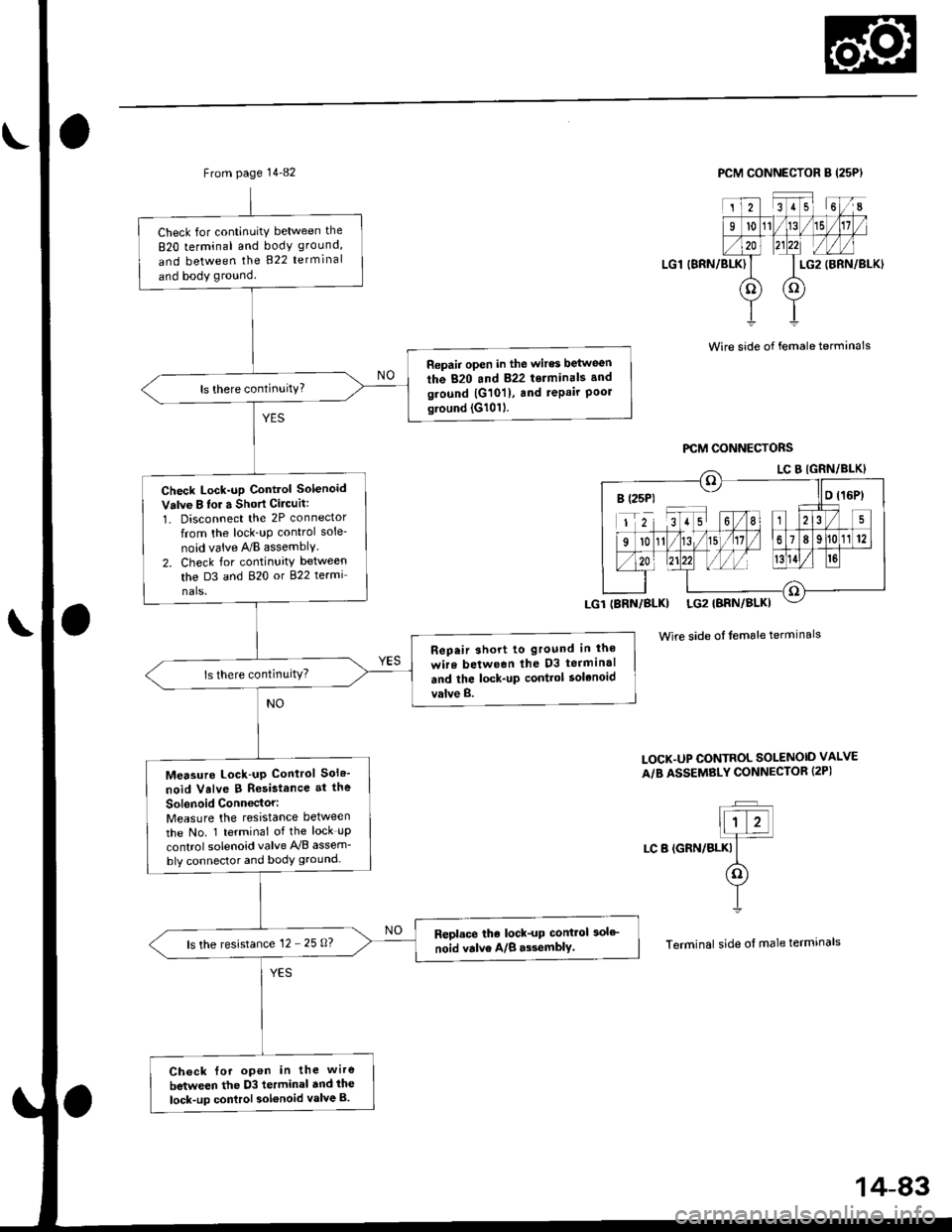
From page 14-82
Check for continuitY between the
820 terminal and body ground,
and between the 822 terminal
and body ground
Repair open in the wires between
the 820 and 822 terminals and
ground |G101), and repair Poolground (G1011.
Check Lock-up Control Solenoid
Valve B lor a Short Cilcuit:
1. Disconnect the 2P connector
from the lock_uP control sole-
noid vaive A/B assemblY.
2. Check for continuity between
the D3 and 820 or 822 termi
nals.
Rep.ir short to ground in lho
wire between lhe D3 terminal
and the lock-up contlol solenoid
valve B.
Measure Lock-up Control Sol6'
noid Valve B Resistance at the
Sol6noid Conn€ctor:Measure the resistance between
the No. 1 terminal of the lock uP
control solenoid valve A'lB assem_
bly connector and body ground-
Repl.ce the lock-up control 3olc
noid valve A/B a$emblY.ls the resistance 12 - 25 0?
Ch6ck {or open in the wire
between the D3 terminal dnd ihe
lock-up control sol€noid valve B.
PCM CONNECTOR B (25PI
LG1 (BRN/BLK)
2351 6I
l011/15
LG2
oo
(BRN/BLKI
Wire side of female terminals
Wire side of female terminals
LOCK.UP CONTROL SOLENOID VALVE
A/B ASSEMBLY CONNECTOR (2PI
t;T�Jllt z!]4
LC B (GRN/BLKI It(o)
YI
Terminal side of male termrnals
B (25P1 - llo t16Pt
14-83
Page 768 of 2189

Electrical Troubleshooting ('gg - 00 Models)
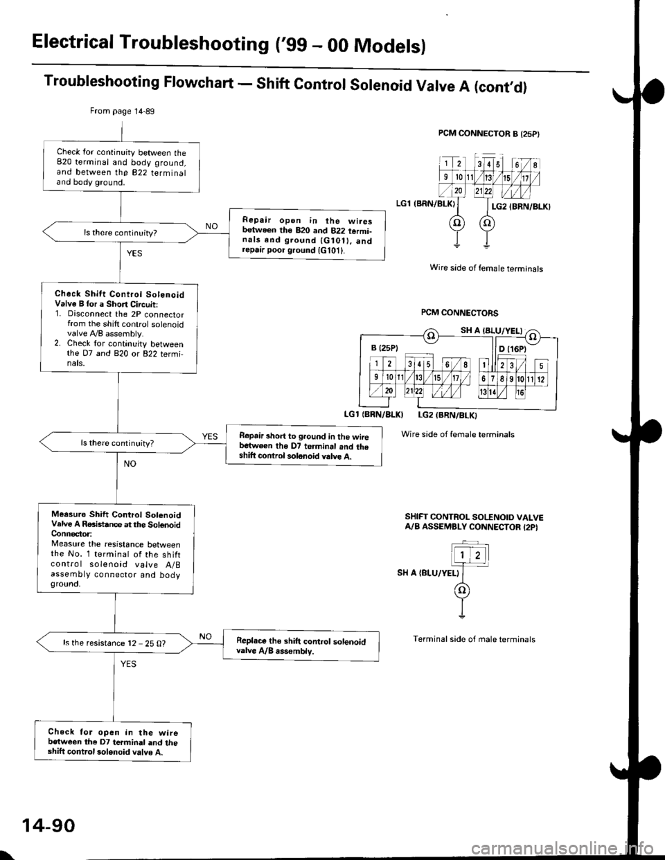
Troubleshooting Flowchart - Shift Control Solenoid Valve A (cont,O)
PCM CONNECTOR B {25P}
LGl (BRN/BLKI
Wire side of female terminals
rcM CONNECTORS
LGl {BBN/BLKI LG2 (BRN/BLKI
Wire side of female terminals
SHIFT CONTROL SO|'INOID VALVEA/B ASSEMBLY CONNECTOR I2PI
SH A {BLU/YELI
From page 14-89
Check lor continuity between the820 terminal and body ground,and between the 822 terminaland body ground.
Repair open in ihe wiresbetween th€ 820 and 822 termi-nals end ground {G10ll. andrepa,r poor ground {G101}.
Check Shitt Control SolenoidValve B for a Short Circuit:1. Disconnect the 2P connectorfrom the shilt control solenoidvalve A,/B assembly.2. Check lor continuity betweenthe D7 and 820 or 822 termi,nals.
R€pair short to ground in the wiiebartwe€n the D7 te.minal and theshift control solonoid valve A.
ls there continuity?
Meesuro Shift Control SolenoidValve A RGistance at the SolenoidConnector:Measure the resistance betweenthe No. 1 terminal of the shiftcontro I solenoid valve A/Bassembty connector and bodygrounct,
Repl.ce tho shift control solenoidvalve A/B rss€mblv.ls the resistance 12 25 O?
Check for open in the wirebetween the D7 termindl and theshift control 3olonoid valve A.
B t25Pt llD t16Pt
\
14-90