Page 1220 of 2189
(From page 19 66)
Check tor an op€n in th€ solenoidcircuit:Measure the voltage between theABS control unit connector appro-priate solenoid circuit terminal*and body ground.' Repsir opon in the appropriateCOM circuit wiro botwoon theABS control unit and modulatolunit.' Repair open in ihe appropriatesol€noid ci.cuit wiro betweentho ABS control unit and modu-lator unit.. Roplaco the modulator unil.
ls there approx.3 V?
Check loi loGe ABS control unitconnoctors. It necessarv, substi-tute a known-good ABS controlunit and recheck.
te
ABS CONTROL UNIT 22P CONNECTOR
Wire side of female terminals
ABS CONTROL UNIT 25P CONNECTOR
\J
FL.OUT {YEL/BLK}DTCConn€clorTerminal
31: FB-lN22PNo. 1
32: FR'OUT22PNo. 12
33: FL IN22PNo.1l
34: FL-OUT22PNo. 10
35: BR-lN26PNo. 13
36: RR-OUT22PNo.2l
37: BL-lN26PNo. 25
38:8I-OUT26PNo. 12
BL.OUT (YELI
Wire side of female terminals
19-67
Page 1223 of 2189

Troubleshooting
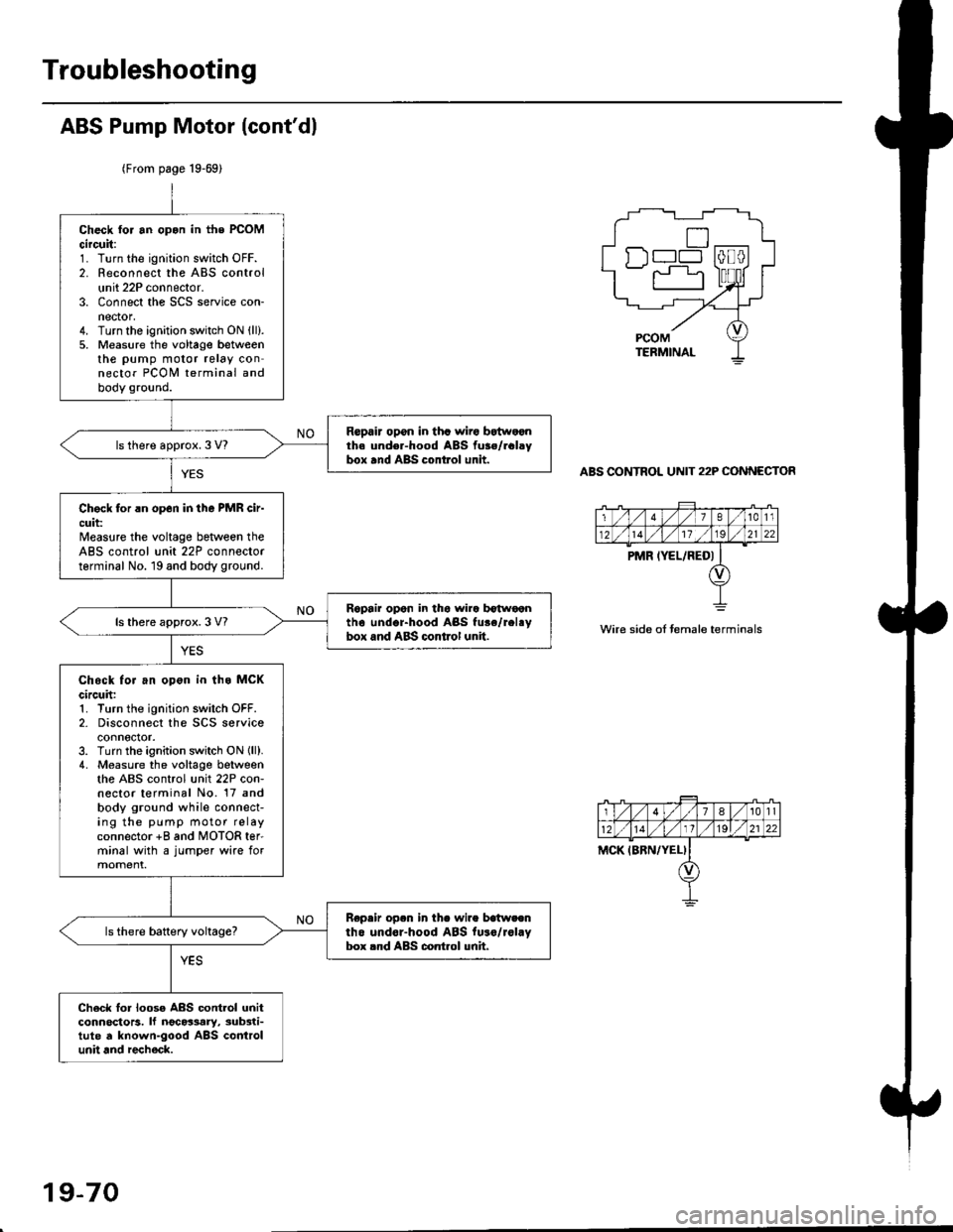
ABS Pump Motor (cont'dl
(From page 19-69)
ABS CONTROL UNIT 22P CONNECTOR
Check tor an opon in the PCOMcircuit:1. Turn the ignition switch OFF.2. Reconnect the ABS controlunit 22P connector.3. Connect the SCS service con-nector,4. Turn the ignition switch ON (ll).
5. Measure the voltage betweenthe pump motor relay connector PCOI,I terminal andbody ground.
Repair opon in tha wiro bEtwoonth. und€r-hood ABS fu3./rclsybox and ABS control unit.ls there approx. 3 V?
Chock for rn op6n in tho PMR cir-cuit:Measure the voltage beNveen theABS control unit 22P connectorterminal No. 19 and body ground.
Ropair opon in tho wira b€twoontho undor-hood ABS fu.e/rel.ybox and ABS control unit.ls there approx. 3 V?
Chock for an opon in ths MCKcircuh:1. Turn the ignition switch OFF.2- Disconnect the SCS serviceconnector.3. Turn the ignition switch ON lll).4. Measure the voltage betweenthe ABS control unit 22P con-nector terminal No. 17 andbody ground while connect-ing the pump motor relayconnector +8 and MOTOR ter'minal with a jumper wire formoment.
Repeir op.n in th. wire batweentho undor-hood ABS fu.o/rol.Vbox rnd ABS control unh.
Ch6ck lor loose ABS contlol unitconnoctors. lf ngc63ary, sub3ti-tute d known-good ABS controlunit and recheck.
n--l
wire side oI temale terminals
19-70
Page 1224 of 2189

tfMain Relay
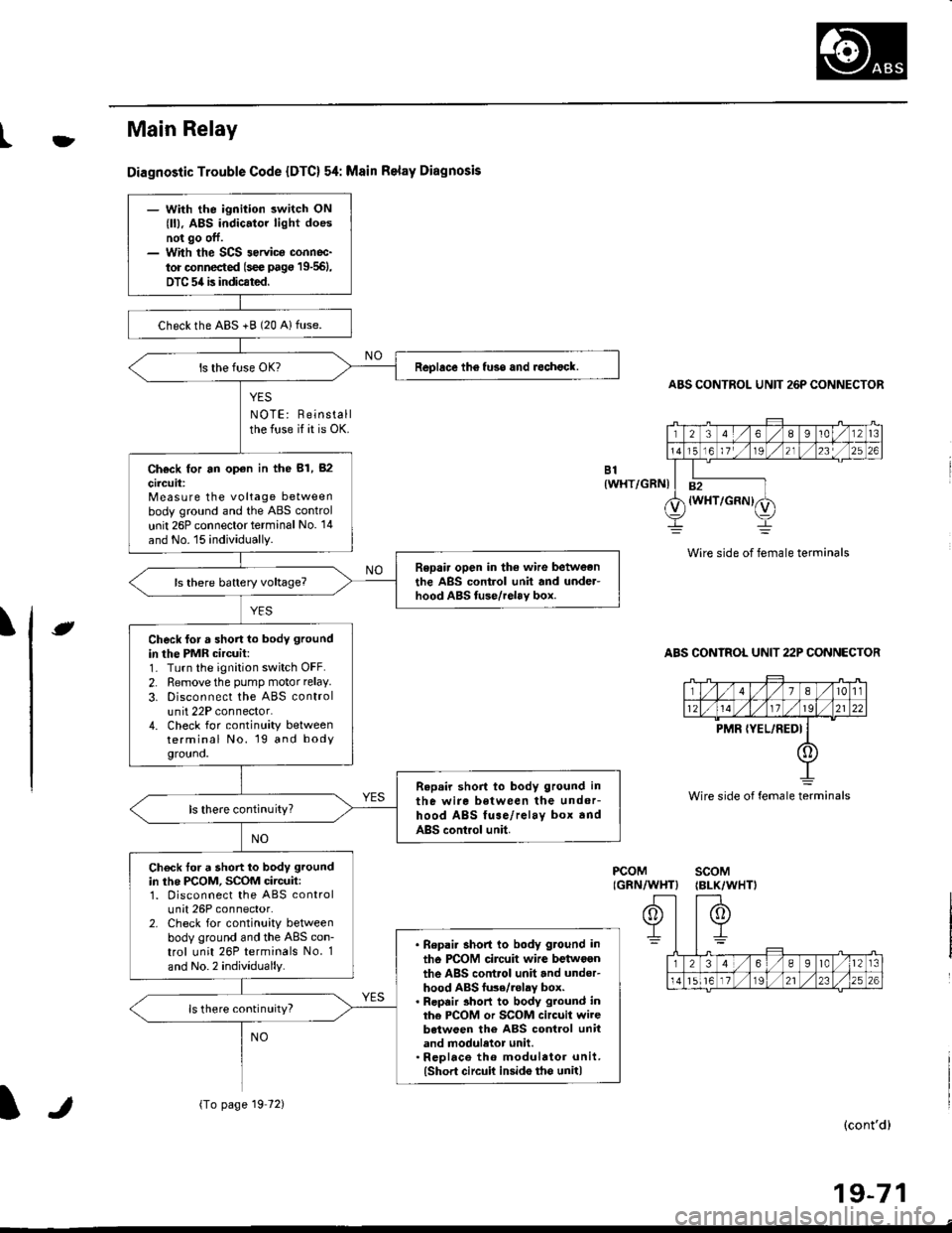
Diagnostic Trouble Code {DTC} 54: Msin Relay Diagnosis
YES
NOTE: Reinstallthe fuse if it is OK.
ABS CONTROL UNIT 26P CONNECTOR
Wire side of female terminals
ABS CONTROL UNIT 22P CONNECTOR
B1{WHT/GRNI
\e
PCOMIGRN/WHT}scoM{BLK/WHTI
(cont'd)
19-71
Wire side of female terminals
- With the ignition switch ON
{ll), ABS indic.tor light doesnot go off.- With the SCS 3ervica connoc-
tor connected (s€e pag€ 19-561,
DTC 54 is indicated.
checkthe ABS +B (20 Alfuse.
Replace th6 fuso and rechock.
Ch€ck for an op€n in the 81, 82
circuit:Measure the voltage betweenbody ground and the ABS control
unit 26P connector terminal No. '14
and No. 15 individually.
Repair open in the wire betweonthe ABS control unit and under-hood ABS tuse/relav box.
Check for a short lo body ground
in the PMR circuit:1- Turn the ignition switch OFF.
2. Remove the pump motor relay.
3. Disconnect the ABS controlunit 22P connector.4. Check for continuity betweenterminal No. 19 and bodygrouno.
Repair short to body ground in
the wire between the undor-hood ABS fuse/relay box andABS control unit.
ls there continuity?
Check tor a short to body ground
in the PCOM, SCOM circuit:1. Disconnect the ABS controlunit 26P connector.2. Check for continuity betweenbody ground and the ABS con-trol unit 26P terminals No. 1
and No.2 individually.
. Bepai. short to body ground in
tho PCOM circuit wire betwoenthe ABS control unit and under-hood ABS fu3e/.olay box.. Repair 3hort to body ground inthe PCOM or SCOM circuit wirebetween the ABS control unitand moduletor unit.. Rcplace th6 modulator unit.(Short circuit insido tho unit)
ls there continuity?
{To page 19 72)lr
Page 1225 of 2189
Troubleshooting
Main Relay (cont'd)
(From page 19'71)
PCOM(GRN/WHTIscoM(BLK/WHT}Check tor a short to powor in thePCOM, SCOM circuit:1. Turn the ignition switch ON r).2. Measure the voltage betweenbody ground and ABS controlunit 26P connector terminalsNo. l and No.2 individually.
. Repair 3hoit to power in ihercOM circuil wire bgtween theABS control unit end unde.-hood ABS fuse/relay box.. Repair sho to powor in thaPCOM oJ SCOM circuit wirobetwoen the ABS control unitand modulator unit.' Repl.co the modul.tor unit.lshort to Dowcr iGido the unit)Replace the ABS control unit.
Vo lta ge
19-72
Page 1231 of 2189
l}
e\
Body ('96 modell
Doors
Front Door Index (4D) ...20-2
Rear Door Index {4Dl .....20-8
Door fndex lzDl3Dl .......20-14
Emblems
f nstallation 20-118
Exterior
Component Location Index ............... 20-93
*Frame Repair Chart .......... 20-120
* Interior
Component Location Index ............... 20-58
Mirrors
Mirror Rep|acement .................. ......... 20-24
Mirror Holder/Gover Replacement ... 20-25
Rearview Mirror Reolacement .......... 20-25
Moonroof
lndex .......... .....................20-50
Opener Cable/Opener and Latch/
Wiper and Washer
Component Location Index .......... ...,. 20-107
Seats and Seat Belts
Gomponent Location Index .......... ..... 20-73
Sub-frame ....20-119
Windshield, Rear Window and Ouarter Glass
Index .......... .....................20-26
Body {'97 modell
Body ('98 modell
Body ('99 modell
Body ('00 model)
20-123
20-131
20-135
20-141
It
Page 1300 of 2189

Dashboard
Gomponent Removal/lnstallation
(cont'd)
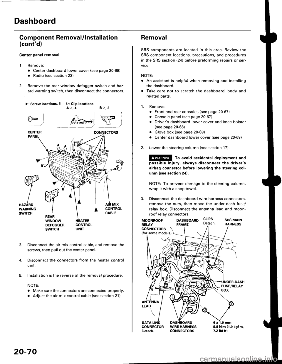
Center panel removal:
1. Remove:
. Center dashboard lower cover (see page 20-69)
. Radio {see section 23)
2. Remove the rear window defogger switch and haz-
ard warning switch, then disconnect the connectors.
>: Screw locations, 5 >: Clip locationsA>,4 B>,3
fii*-)
CENTERPANEI.
rt-xR.
W
IHAZARDWARNINGswlTcH
r44 "
F.IZvl
IIREARwtNoowOEFOGGERswtrcH
MtxCONTNOLCABLE
3. Disconnect the air mix control cable, and remove the
screws, then pull out the center panel.
4. Disconnect the connectors from the heater control
u nit.
5. Installation is the reverse of the removal procedure.
NOTE:
. Make sure the connectors are connected properly.
. Adjust the air mix control cable (see section 21).
20-70
Removal
SRS components are located in this area. Review the
SRS component locations, precautions, and procedures
in the SRS section (24) before preforming repairs or ser-
vice.
NOTE:
. An assistant is helpful when removing and installing
the dashboard.
. Take care not to scratch the dashboard, body and
related parts.
1. Remove:
o Front and rear consoles (see page 20-67)
. Console panel (see page 2O 67),
. Driver's dashboard lower cover and knee bolster(see page 20-68)
. Glove box (see page 20-69)
. Center dashboard lower cover (see page 20-69i
2. Lower the steering column (see section 17).
@ To avoid accidental deplovment and
possible injury, always disconnect the driver's
airbag connector belore lowering the steering col-
umn lsee section 241.
NOTE: To prevent damage to the steering column,
wrap it with a shop towel.
3. Disconnect the dashboard wire harness connectors,
remove the nuts, then move the under-dash fuse/
relay box. Disconnect the antenna lead and moon-
roof relay connectors.
DASHBOARD cltPs
CONNECTORS(for some models)
MOONROOFRELAY
ANTENNALEAO
FRAME
SRS MAINHARNESS
9.8 N.m (1.0 kgf m,7.2lbt.ltl
DATACONNECTOR WIRE HARNESSDetach. CONNECTORS
Page 1382 of 2189
Troubleshooting -'96 - 98 Models
Blower Motor Speed
HEATER FAN SWITCH 6P CONNECTOR
Wire side of female terminals
21-a
Blower motor runs. but one orrnore speeds are inoperative,
Chsck for a short or an open inthe wire{s}:Turn the ignition switch ON {ll),and the heater fan switch OFF.
Does the blower motor run?
Check for a shon in th6 wirels):1. Turn the ignition switch OFF.2. Disconnect the blower motor2P connector,3. Remove the center dashboardlower cover (see section 20),and disconnect the heater lanswitch 6P connector,4. Disconnect the blower resistor 4P connector,5. Check for continuity betweenthe No. 2,3, 4 and 5lerminalsof the heater fan switch 6Pconnector and body ground
individually.
ls there continuity?Reolace the heater fan switch,
Repair short in the wire(s)beiween the blower resistor, theheater tan switch and the blowermotor,
To page 21 9
Page 1385 of 2189
From page 2l 10
Check for an open in the wire:
1. Turn the ignition switch OFF,and disconnect the iLrmPer
2. Remove the center dashboardlower cover (see section 20),
and disconnect the heater fanswitch 6P connector.3. Turn the ignition switch ON (ll).
4. Measure the voltage between
the No. 3 terminal and bodygrou nd.
Repair op.n in th6 wiro betw€enthe blower motor and tho heaterfan switch.
Check for an open in the wire:
1. Turn the ignition switch OFF.2. Check for continuity between
the No. 1 terminal of the heatertan switch 6P connector and
body ground.
Reolaco tho heater fan iwitch
Check tor an op€n in the wire
betw.en the heater tan switchand body ground. ll th€ wilo b OK,
check tor poor ground at G401 and
G102.
HEATER FAN SWITCH 5P CONNECTOR
Wire side oI female terminals
(cont'd)
21-11