Page 585 of 2189

Transmission Assembly
I
Removal
@. Make sure iacks and safety stands are placed prop€dy,
and hoist brackets are atlach€d to correct position on
the enginc.
. Apply parking brake and block rear whosls so car will
nol roll olf stands and lall on you while working under
it.
CAUTION: Use fender covers to svoid damaging painted
surfaces.
1. Disconnect the negative {-) cable first, then the pos-
itive (+) cable from the battery'
Drain transmission oil {see page 13-3).
Remove the intake air tube. intake air duct and air
cleaner housing assembly (see section 5).
Disconnect the starter motor cables, transmission
ground wire and back-up light switch connector.
6x1.0 mm BACK-UP LIGHT
9.8 N.m (1.0 ksf.m, 7.2 lbI.ft) swlTcH CoNNECTOR
8x 1 .25 mm8.8 N.m {0.9 kgt.m,6.5 lbf.ftl
\
ARTER
5. Remove the wire harness clamps.
vssCONNECTOR
6. Disconnect the vehicle speed sensor (VSS) connec-
ror.
Remove the clutch line bracket, clutch line clamp,
and slave cvlinder.
CAUTION:
. Do not opsr.te tho clutdh pedal once the 3lavc
cylindor has b6on romoved.
. Tske care not to bend tha clutch lin6.
7.
(cont'd)
13-5
Page 628 of 2189

Transmission Assembly
l
,
{
Removal
@Make sure iacks and safoty stands are placad plop-
erly (3ee section l).
Apply parking braks and block rear wheels so car
will not roll off stands and fall on you while working
under il.
CAUTION: Us6 fonder cove6 to avoid damaging painted
sudaces.
Disconnect the negative (-) cable from the battery,
then the positive (+l cable.
Drain the transmission oil. then reinstall the drain
plug with a new washer (see page 13-47).
Remove the intake air duct and the air cleaner hous-
ing assembly (see s€ction 5).
Disconnect the back-up light switch connector and
the transmission ground wire.
Remove the lower radiator hose clamp from the
transmission hanger B.
L
8 x 1 .25 mm22Nm12.2kgl'm�,
LOWER RADIATORHOSE CLAMP
16 rbtft)
13-48
7.
Bemove the wire harness clamps.
Disconnect the starter motor cables and the vehicle
speed sensor (VSS) connector.
8 x 1.25 mm8.8 N.m (0.9 kgf.m,6.5 tbtftl
STARTERMOTORCABLES
8. Remove the clutch line bracket and the slav6 cylin-
oer.
NOTE: Do not operate the clutch pedal once the
slave cylinder has been removed.
\J
Page 1104 of 2189

Steering Gearbox
Removal {cont'dl
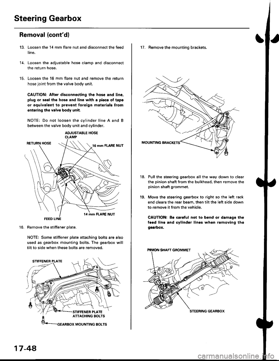
Loosen the 14 mm flare nut and disconnect the feed
line.
Loosen the adjustable hose clamp and disconnect
the return hose.
Loosen the 16 mm flare nut and remove the return
hose joint trom the valve body unit.
CAUTION: After disconnecting lhe hos6 and lin6.
plug or seal the hose and line with a pioca ol tapa
or equivalent to prevenl foreign matorials trom
entsring the valve body unit.
NOTE: Do not loosen the cvlinder line A and
between the valve body unit and cylinder.
ADJUSTABLE HOSECLAMP
Remove the stiffener Dlate.
NOTE: Some stiffener plate attaching bolts are also
used as gearbox mounting bolts. The gearbox will
tilt to side when these bolts are removed.
13.
14.
t9.
16.
17-48,
17. Remove the mounting brackets.
Pull the steering gearbox all the way down to clear
the pinion shaft from the bulkhead. then remove the
pinion shaft grommet.
Move the steering gesrbox to right so the left rack
end clears the rear beam, then tilt the left side down
to remove it from the vehicle,
CAUTION: Be careful not io bend or damage the
fagd ling and cylindsr lin99 whgn rgmoving thg
ggarbox,
18.
STEERING GEANEOX
Page 1122 of 2189

Steering Gearbox
Installation (cont'dl
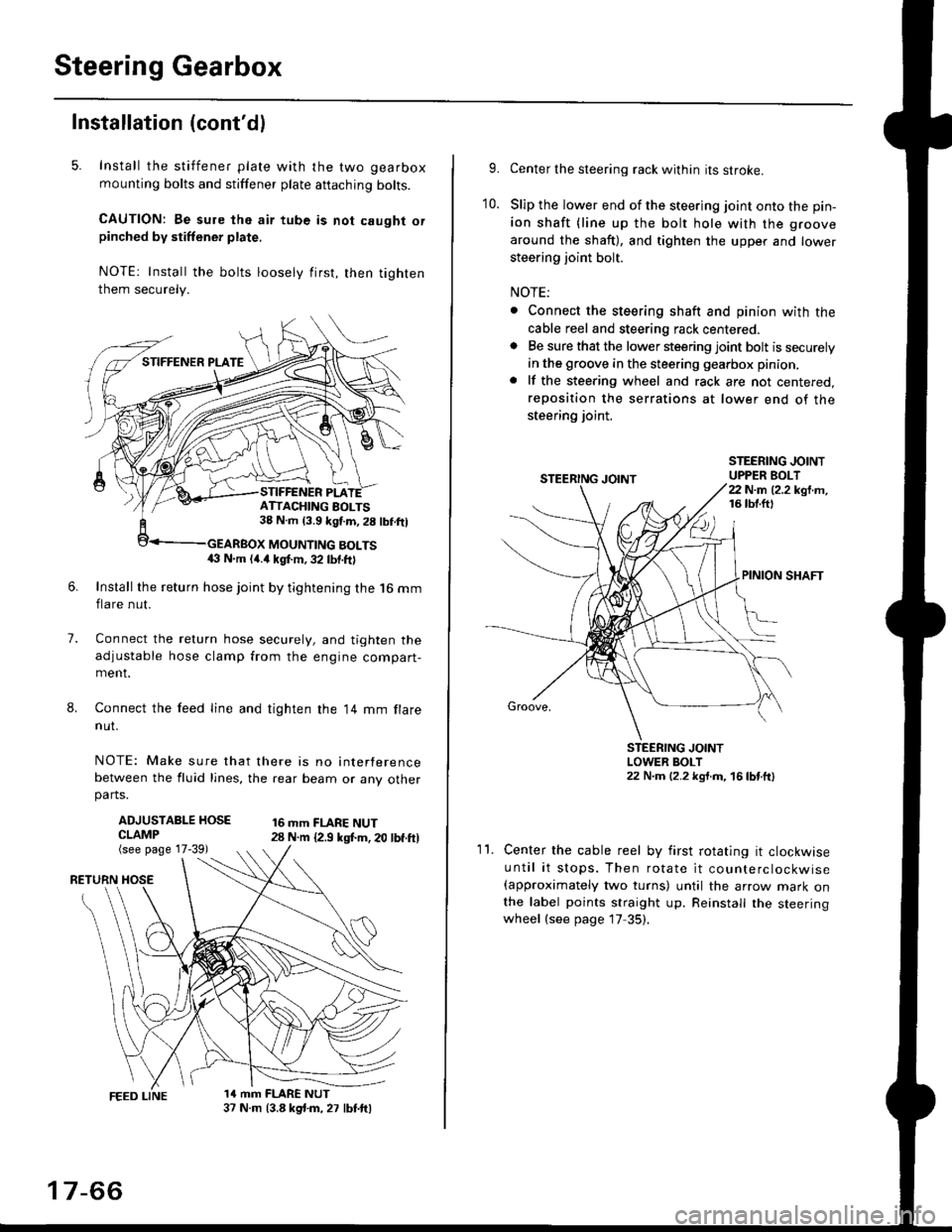
5. Install the stiffener plate with the two gearbox
mounting bolts and stiffener plate aftaching bolts.
CAUTION: Be sure the air tube is not caught orpinched by stiffener plate,
NOTE: Install the bolts loosely first, then tighten
them securely.
7.
8.
6.Install the return hose joint by tightening the l6 mm
flare nut.
Connect the relurn hose securely, and tighten the
adjustable hose clamp from the engine compart-ment.
Connect the feed line and tighten the 14 mm flare
nut.
NOTE: Make sure that there is no interference
between the fluid lines, the rear beam or any otherparts.
ADJUSTABLE HOSECLAMP(see page 17-39)
16 mm FLARE NUT28 N.m {2.9 ksl.m. 20 lbf.ft)
RETURN
1a mm FLARE NUT37 N.m (3.8 kg{.m, 27 lbt.ftl
ATTACHING AOLTS38 N.m 13.9 kgf.m, 28 lbf.ftl
MOUNTING BOLTS(} N.m (4.a kgt m, 32 lbf.ftl
17-66
9.Center the steering rack within its stroke.
Slip the lower end of the steering joint onto the pin-
ion shaft (line up the bolt hole with the groove
around the shaft), and tighten the upper and lower
steering joint bolt.
NOTE:
. Connect the steering shaft and pinion with the
cable reel and steering rack centered.. Be sure that the lower steering joint bolt is securely
in the groove in the steering gearbox pinion.
. lf the steering wheel and rack are not centered,
reposition the serrations at lower end of the
steering joint.
10.
STEERING JOINTUPPER BOLT22 N.m (2.2 kgf.m,16 tbt.ftl
PINION SHAFT
Groove,
STEERING JOINTLOWER BOLT22 N.m (2.2 kgt.m, 16lbtttl
11.Center the cable reel by first rotating it clockwise
until it stops. Then rotate it counterclockwise(approximately two turns) until the arrow mark onthe label points straight up. Reinstall the steeringwheel (see page 17 35).
Page 1178 of 2189

Rear Brake Pads
Inspection and Replacement
Never use an air hose or dry brush to clean brakeassemblies.
Use an OsHA-apptoved vacuum cl€aner to avoidbreathing brake dust,
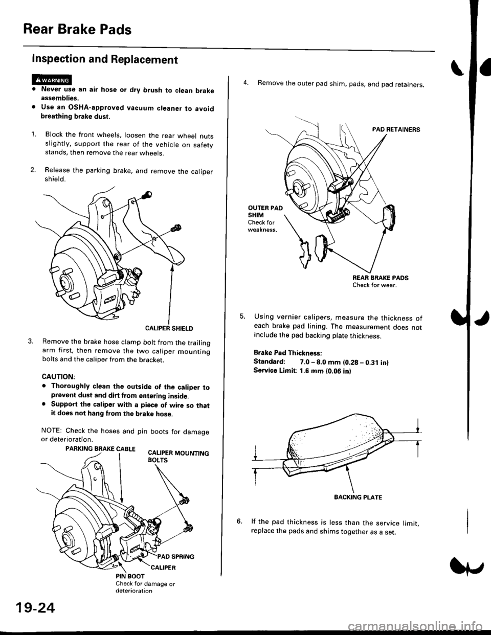
Block the front wheels, loosen the rear wneet nutsslightly, support the rear of the vehicle on safetystands, then remove the rear wheels.
Release the parking brake, and remove the calioersh ield.
CALIPER SHIELD
Remove the brake hose clamp bolt from the trailingarm first, then remove the two caliper mountingbolts and the caliper from the bracket.
CAUTION:
. Thoroughly clean the outside of the caliDer toprevent dust and dirt trom entering inside.. Support the calipor with a pieco of wire so thatit does not hang fuom the brake hose.
NOTEr Check the hoses and pin boots for damageor deterioration.
PARKING BRAKE CABLE ^.. ._-_ ---.
'L
19-24
4. Remove the outer pad shim, pads, and pad retainers.
PAO RETAINERS
OUTER PAOSHIMCheck for
REAR BRAKE PADSCheck for wear.
Using vernier calipers, measure the thickness ofeach brake pad lining. The measurement does notanclude the pad backing plate thickness.
Brake Pad Thickness:
Standard: 7.0 - 8.0 mm {0.28 - 0.31 in}Service Limit: 1.5 mm {0.06 in}
lf the pad thickness is less than the service limit,replace the pads and shims together as a set.
BACKING PI-ATE