Page 1258 of 2189

Windshield
Removal
CAUTION:
. Put on gloves to plotest your h8nds.
. Use seat covers to avoid damaging any surfaces.
1. To remove the windshield, first remove the:. Rearview mirror (see page 20-25)
. Sunvisors and holders (see page 20-64)
. Front pillar trim (see pages 20-59, 60, 61)
! Windshield wiper arms and cowl cover (see page
20-1131
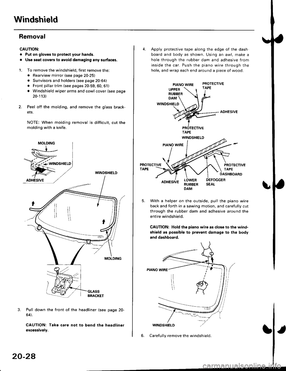
Peel off the molding, and remove the glass brack-
ers.
NOTE: When molding removal is difficult, cut the
molding with a knife.
WINDSHIELO
3. Pull down the front of the headliner (see page 20-
64).
CAUTION: Take care not to bend the headlinet
excsssively.
MOLDING
20-24
4. Apply protective tape along the edge of the dash
board and body as shown. Using an awl, make a
hole through the rubber dam and adhesive from
inside the car. Push the piano wire through the
hole, and wrap each end around a piece of wood-
PIANO WIREPROTECTIVE
UPPERRUBBER| '1"
DAM
WINDSHIELO
AOHESIVE
RUBBERDAM
With a helper on the outside, pull the piano wire
back and forth in a sawing motion, and carefully cut
through the rubber dam and adhesive around the
entire windshield.
CAUTION: Hold the piano wile as close to ihe wind-
shield as possible to prevent damage to the body
and dashboard.
WINDSHIELD
6. Carefully remove the windshield.
Page 1275 of 2189
Removal
2Oi
CAUTION:
. Put on gloves to protect your hands.
. Use seat covers to avoid damaging any surfaces.
1. To remove the quarter glass, first remove the:
. Rear seat-back and rear seat cushion (see page
20_81)
o Slde trim panel (see page 20-611
. Rear shelf (see page 20-61)
o Upper anchor bolt from the front seat belt (see
page 20-86)
. Ouarter trim panel (see page 20-6'l)
2. From inside the car. use a knife to cut through the
quarter glass adhesive allthe way around.
NOTE:
. lf the quarter glass is to be reinstalled, take care
not to damage the molding.
. Apply protective tape along the edge ofthe entire
quaner glass oPening flange
D
I
GLASS
Upper portion:
ADHESIVE
PROTECTIVETAPE
Rear edge portion:
Pillar portion:
Carefully remove the quarter glass.
NOTE: Check the molding for damage, and replace
it if necessary.
3.
TAPE
20-45
Page 1296 of 2189

Carpet
Replacement
SRS components are located in this area. Review the SRS
component locations, precautions, and procedures in the
SRS section {24} before performing repairs or service.
1. Remove:
. Front seat (see page 2O-7 4l
. Rear seat cushion (see pages 20 79, 80, 81)
o Kick panel (see pages 20-59, 60, 61)
o Center pillar lowertrim panel i4D, see page 20-59)
. Front seat belt iower anchor (2Dl3D, see page 20-
86)
. Side trim (see pages 20-59, 60,61)
o Front and rear consoles
. Console panel
Remove the SRS unit covers.
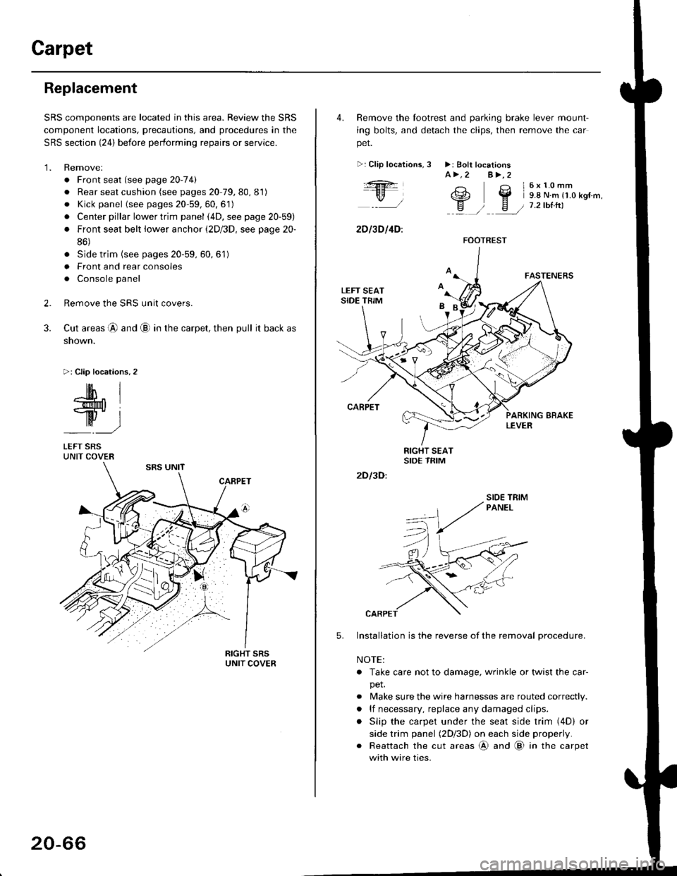
Cut areas @ and @ in the carpet, then pull it back as
snown.
>: Clip locations,2
2.
3.
-lM- IlMt l
ry-l
LEFT SRSUNIT COVER
20-66
4. Remove the tootrest and parking brake lever mount-
ing bolts, and detach the clips, then remove the car
pet.
>:Clip localions,
:ft
\/l
2D l3D l4D:
3 >: Bolt locationsA>.2 A>,2
3 l6x10mm
e2 Y 9.8 N.m r1.o kgr'm,
H ) E / 7.2tbtrtl::a /
5.
2D I3D:
Installation is the reverse of the removal procedure.
NOTE:
. Take care not to damage. wrinkle or twist the car-
pet.
. Make sure the wire harnesses are routed correctly.
. lf necessary, replace any damaged clips.
. Slip the carpet under the seat side trim (4D) or
side trim panel (2Dl3D) on each side properly.
. Reattach the cut areas @ and @ in the carpet
with wire ties.
FOOTREST
SIOE TBIM
Page 1301 of 2189
Remove the following parts Irom the dashboard'
. Driver's dashboard side cover
o Passenger's dashboard lower cover
. Dashboard center lid
Disconnect the connectors and air mix control cable'
6x1.0mm9.8 N.m 11.0 kgl.m,
D>, 1
@7 2'orftl - ---//_._J
,{nil Lll , ,"o
Ift#5 L //Hl Wlj%u|5 i//Wt qT
W72-t11 7'::--J
>: Clip locationsA>, 1 B>, 1
Loosen the bolt.
DASHBOARD
AIR MIX CONTROL
CONNECTORS
FRONT PASSENGER'SAIRBAG CONNECTOR
Remove the bolts, then lift and remove the dashboard'
CAUTION: Use proteqtive plates on the bottom ot the front pillar trim'(cont'd)
20-71
M,::;:"lx3T:iJnif:3lilH:fl"*:1::f"*'il;ili"'"
disconnect rhe front passeneer's airbas
>: Bolt, screw locaiions
A>,7B>, 1
,i( 8x125mm(!,@ 22 N.m t2.2 kstm,-v, 16 tbf.ftl
8xl.25mm I22 N.m 12.2 kgt'm, I'"tt:___J
c>, 1
@
c>,6
Page 1315 of 2189

Front Seat Belt
Replacement
CAUTION: Check the front seat belts for damage, and
replace them it necessary. Be carolul not to damage
them during removal and installation.
Front seat belt removal (4Dl:
1.Slide the front seat forward fully.
Remove the center pillar lower trim panel (see page
20-59).
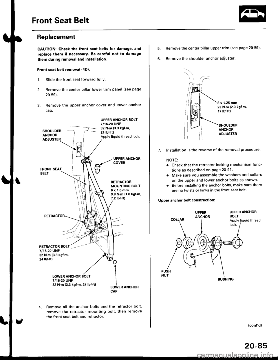
Remove the upper anchor cover and lower anchor
cap.
SHOULDERANCHOR
UPPER ANCHOR BOLT7/16-20 UNF32 N.m (3.3 kgit m,24 lbf.ft)Apply liquid thread lock.
2.
3.
FRONT SEATBELT
RETRACTOR
RETRACTORMOUNTING BOLT6x1.0mm9.8Nm(1.0kgf.m.7.2 tbf.ftl
ER ANCHOR
Remove all the anchor bolts and the retractor bolt,
remove the retractor mounting bolt, then remove
the front seat belt and retractor.
1
I
ILOWCAP
7/1&20 UNF32 N.m (3.3 kgl.m.24 rbl.ftl
7/16-20 UNF32 N.m {3.3 kgf.m,24lbf.ft}
6.
8 x 1.25 mm23 N.m {2.3 kgt'm,17 tbf.ft)
ANCHORADJUSTER
7. Installation is the reverse of the removal procedure
NOTE:
. Check that the retractor locking mechanism func-
tions as described on page 20-91.
. Make sure you assemble the washers and collars
on the uDDer and lower anchor bolts as shown.
. Before installing the anchor bolts, make sure there
are no twists or kinks in the front seat belt.
Upper anchor boh construciion:
UPPER ANCHORBOLT
Remove the center pillar upper trim (see page 20-59)
Remove the shoulder anchor adjuster.
UPPER
COLLARApply liquid thread
(cont'd)
20-85
SUSHING