1997 HONDA CIVIC audio system
[x] Cancel search: audio systemPage 1509 of 2189
D
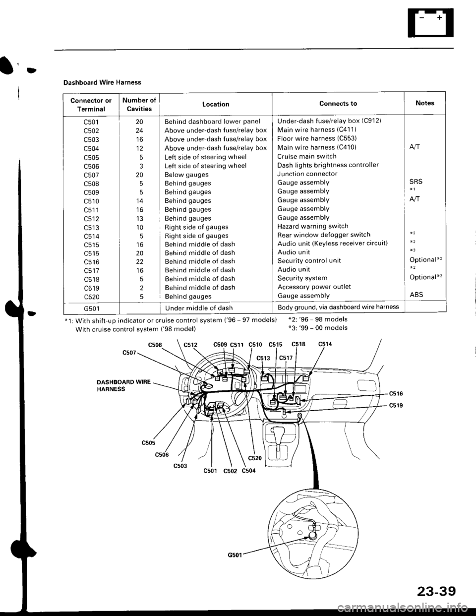
Dashboard Wire Harness
Connector ol
Terminal
Numbel of
CavitiesLocationConnects toNotes
c501
c502
c503
c504
c505
c507
c508
c509
c510
c513
c514
c515
c516
c518
c519
c520
20
24
to
12
5
3
20
5
5
14
r0
5
20
22
5
2
5
Behind dashboard lower panel
Above under-dash luse/relay box
Above under dash Iuse/relay box
Above under dash tuse/relay box
Left side of steering wheel
Left side of steering wheel
Below gauges
Behind gauges
Behind gauges
Behind gauges
Behind gauges
Behind gauges
Right side ot gauges
Right side oI gauges
Beh ind middle of dash
Behind middle of dash
Behind middle of dash
Behind middle of dash
Behind middle of dash
Behind middle of dash
Behind gauges
Under-dash {use/relay box (C912)
Main wire harness 1C411)
Floor wire harness (C553)
Main wire harness (C410)
Cruise main switch
Dash lights brightness controller
Junction connector
Gauge assembly
Gauge assembly
Gauge assembly
Gauge assembly
Gauge assembly
Hazard warning switch
Rear window defogger switch
Audio unit (Keyless receiver circuit)
Audio unit
Security control unit
Audio unit
Security system
Accessory power outlet
Gauge assembly
A"r
SRS
A,/r
Optio nal*'�
Option al*'�
ABS
G501Under middle ol dashBody ground, via dashboard wire harness
*1: With shiit-up indicator or cruise control system ('96 - 97 models)
With cruise control system ('98 model)
c509 C511 c510 c515
13 lc5l7
*2: '96 98 models*3: '99 - 00 models
c508
DASHSOARD WIREHARNESS
c501
c520
c502 c504
23-39
Page 1533 of 2189
(l'-
Fuse NumberAmpswire ColorComponent(s) or Circuitlsl Protect€d
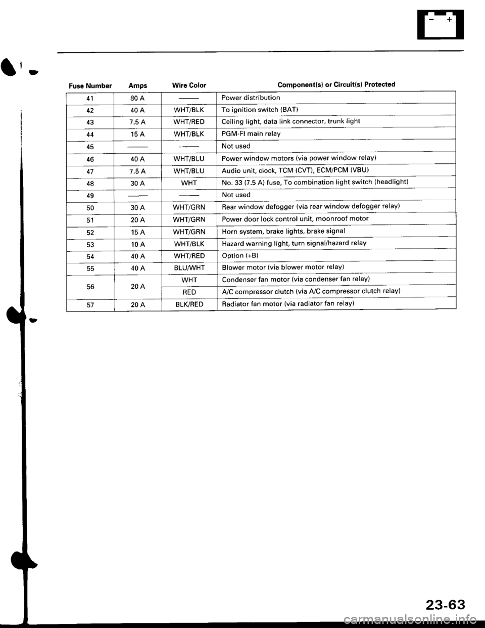
4180APower distribution
4240AWHT/BLKTo ignition switch (BAT)
437.5 AWHT/REDCeiling light, data link connector, trunk light
4415 AWHT/BLKPGM-Fl main relay
Not used
4640AWHT/BLUPower window motors (via power window relay)
477.5 AWHT/BLUAudio unit, clock, TCM (CVT), ECM/PCM (VBU)
4830AWHTNo.33 (7.5 A) fuse, To combination light switch (headlight)
49Not used
5030AWHT/GRNRear window defogger (via rear window defogger relay)
cl20AWHT/GRNPower door lock control unit, moonroof motor
15 AWHT/GRNHorn system, brake lights, brake signal
10 AWHT/BLKHazard warning light, turn signal/hazard rclay
54404WHT/REDOption {+B)
5540ABLU,A/VHTBlower motor (via blower motor relay)
204WHTCondenser fan motor (via condenser fan relay)
REDl'lc compressor clutch (via IVC compressor clutch relay)
204BLVBEDRadiator fan motor (via radiator fan relay)
23-6
Page 1535 of 2189
lr-
Fuse NumberAmpswire ColorComponent{sl or Circuit(sl Protected
*1r '96 - 98 models*2r '98 model*3: '99 - 00 models
,lNot used
2Not used
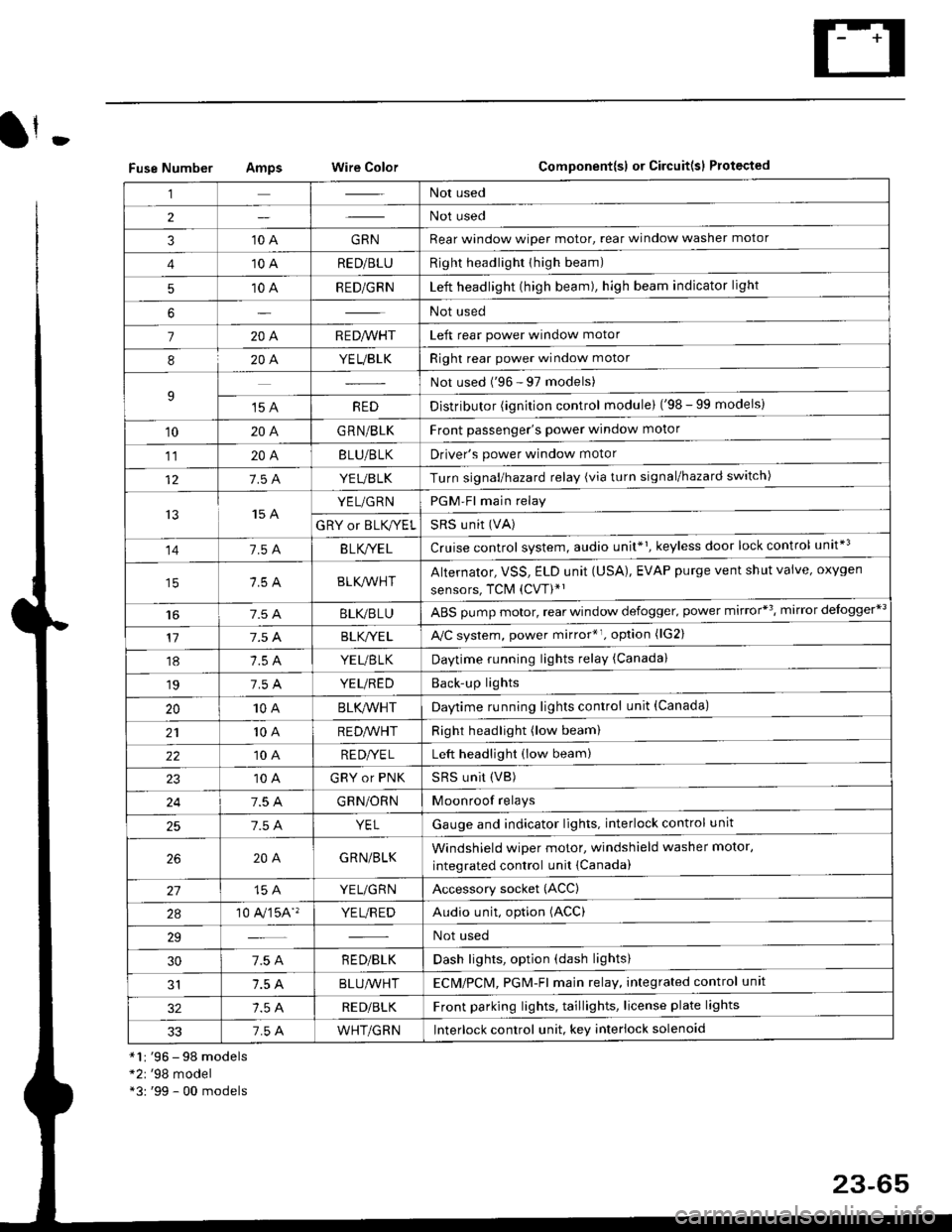
310 AGRNRear window wioer motor, rear window washer motor
410 ARED/BLURight headlighr thigh beam)
510 ARED/GRNLeft headlight (high beam), high beam indicator light
6Not used
7204R E D/VVHTLeft rear power window motor
820A.YEUBLKRight rear power window motor
9Not used ('96 - 97 models)
't5 AREDDistributor (ignition control module) ('98 - 99 models)
10204G RN/BLKFront passenger's power window motor
1120ABLU/BLKDriver's power window motor
127.5 AYEUBLKTurn signal/hazard relay (via turn signal/hazard switch)
t515 AYEL/GRNPGM-Fl main relay
GRY or BLK,^/ELSRS u nit (VA)
141.54B LK/YE LCruise control system, audio unit*1, keyless door lock control unit*3
BLK/lr'r'HTAlternator, VSS, ELD unit (USA), EVAP purge vent shut valve, oxygen
sensors, TCM (CVT)*'
t6BLI(,/BLUABS pump motor, rear window defogger. power mirror*3, mirror delogger*3
177.5 ABLK,/YE LA,/C system, power mirror*r. option (lG2)
18YEUBTKDaytime running lights relay (Canada)
197.5 AYEUREDBack'up lights
2010ABLK/VVHTDaytime running lights control unit (Canada)
2110 AREDA/VHTRight headlight (low beam)
2210 ARE DI/E LLeft headlight (low beam)
10 AGRY or PNKSRS UNit (VB)
247.5 AGRN/ORNMoonroof relays
257.5 AYELGauge and indicator lights. interlock control unit
204GRN/BLKWindshield wiper motor, windshield washer motor,
integrated control unit {Canada)
15 AYEL/GRNAccessory socket (ACC)
2a10 A,/'�]5A''YE L/R EDAudio unit, option (ACC)
29Not used
307.5 AR ED/BLKDash lights, option (dash lights)
1.5 ABLUA/VHTECM/PCl\4, PGM-Fl majn relay, integrated control unit
RED/BLKFront parking lights, taillights, license plate lights
337.5 AWHT/GRNlnterlock control unit. key interlock solenoid
23-65
Page 1544 of 2189
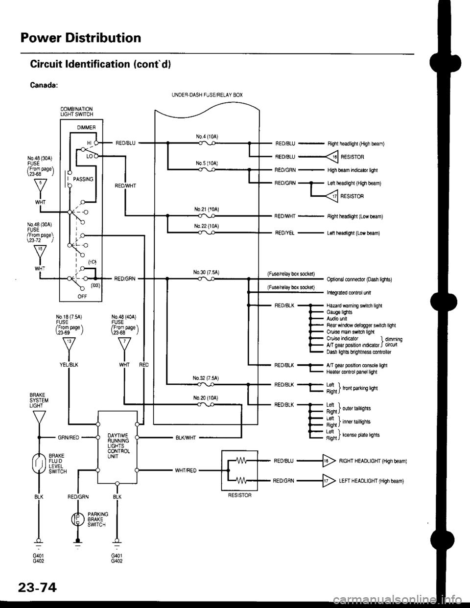
Power Distribution
Circuit ldentification (cont'd)
Canada:
COMBINATIONLIGHT SWITCH
N0.48 {30A)
RED/BLU - Right headlighl (High boam)
FEDiBLU ----< REstsTOR
REo/GRN - HiJh beam indicator lighl
BEo/GRN - Left headlighl iH,gh beam)
L
FEo/YEL - L€ll headlight (Low beam)
(Fuse/lelay box sockel)Optional conneclor (oash lighs)
Inleg6led conlrcl unil
- Hazard wanirE swilch lighl
i- Gauge lEhts
l- Audio unil
l- Re& Yrindow delogg8r swili
t- Ctuise main swrdr ligh
l- C/uise indEator l
E g"ffiry:'l,:1':::1
Refi window delog$r swildr light
Ctuise indicalor 1 dimming,T geal posilion indicator J circu(Dasn lghls brignmess co oller
BRAKESYSTEMLIGHT
V
I
l- GFf
,,4,,0*,lf tIFLUDII ,j I LEVEL
Y
SWTCH
I8LKI
I
I
I:
G401G402
REo/BLK - l/T ged position console lqhl- Hqalor codrot panel tighl
REO/BLK -F- Lefi ) .l- g;n1J lron 9arrn! qm
FEDiBLK + Letl I
F Rqn J ouer larrqns
- I Al, I
{- i'-;*; inne' raittiotts
E fifi]t'"nt"o't't'sn"
*ro,rru -$ RcHT HEADLIGHT (Hrgh beam)
BEDiGRN -+ LEFI H EADLIGHT (High beam)
I BLK
IIPARKING IEFAKE IswrrcH I
I:
G401G402
UNDER,DASH FUSE/RELAY 8OX
lo| | PASSTNGto
/Fforn page\\a-68 l
N0.48 {304)FUSE/From page\\23-72 )
N0.18 (7.54)FUSE/From page \\?3-69 J
v
YIYEUBLK
N0.48 (40A)FUSE/From paqe \\23-68 - ,/
RED6RN
23-74
Page 1657 of 2189
Stereo Sound System
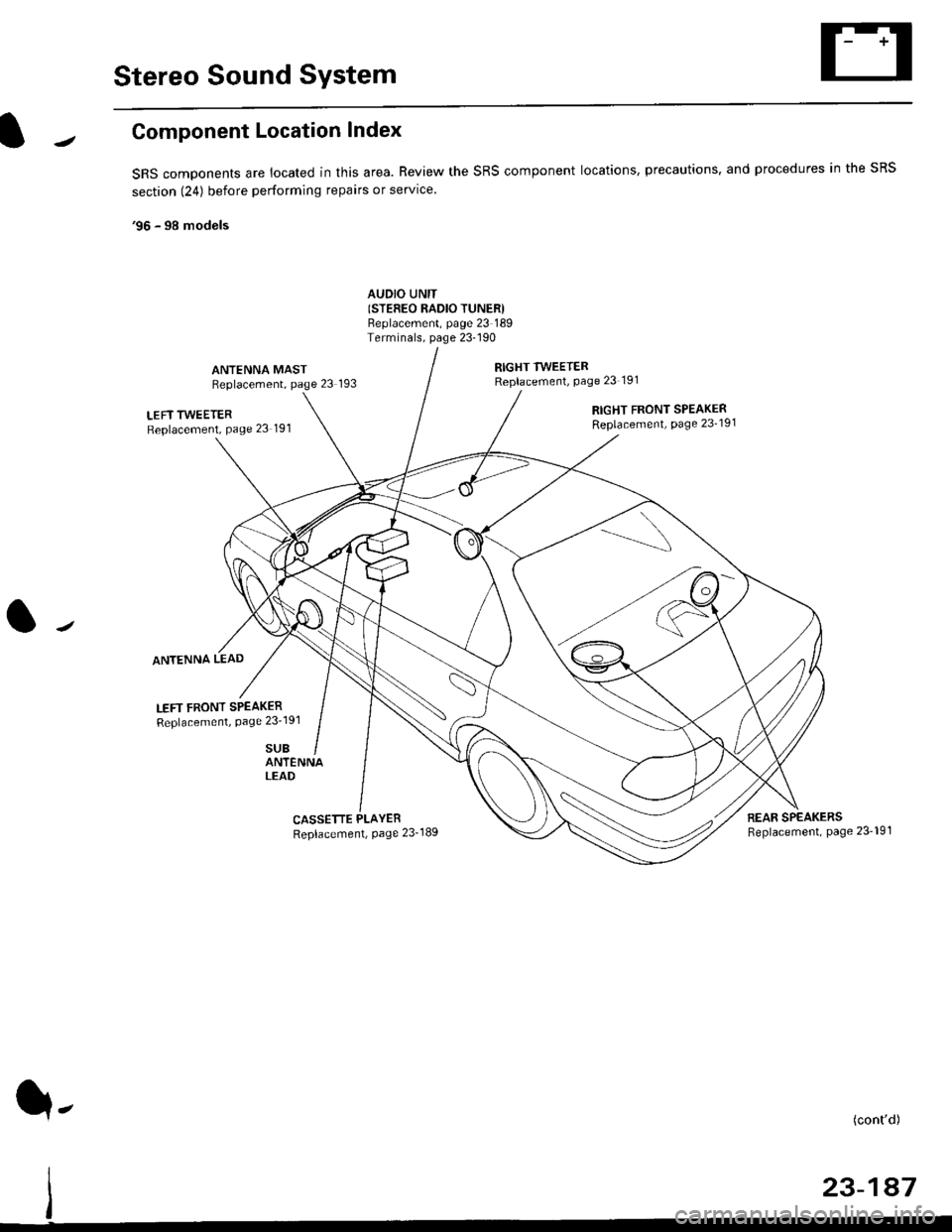
Component Location Index
SRS components are located in this area. Review the SRS component locations, precautions. and procedures in the SRS
section (24) before performing repairs or service.
'96 - 98 models
AUDIO UNIT(STEFEO RADIO TUNERIBeplacement, page 23 189Terminals, page 23-190
ANTENNA MASTReplacement, page 23 193
RIGHT TWEETERReplacement, Page 23 191
LEFT TWEETERReplacement, Page 23 191
ANTENNA LEAD
LEFT FRONT SPEAKER
Replacement, Page 23'191
SUB
RIGHT FRONT SPEAKERReplacement, page 23'191
ANTENNALEAD
CASSETTE PLAYER
Replacement, Page 23-189REAR SPEAKERSReplacement, page 23- 19'l
(cont'd)
23-147
q-
Page 1658 of 2189
Stereo Sound System
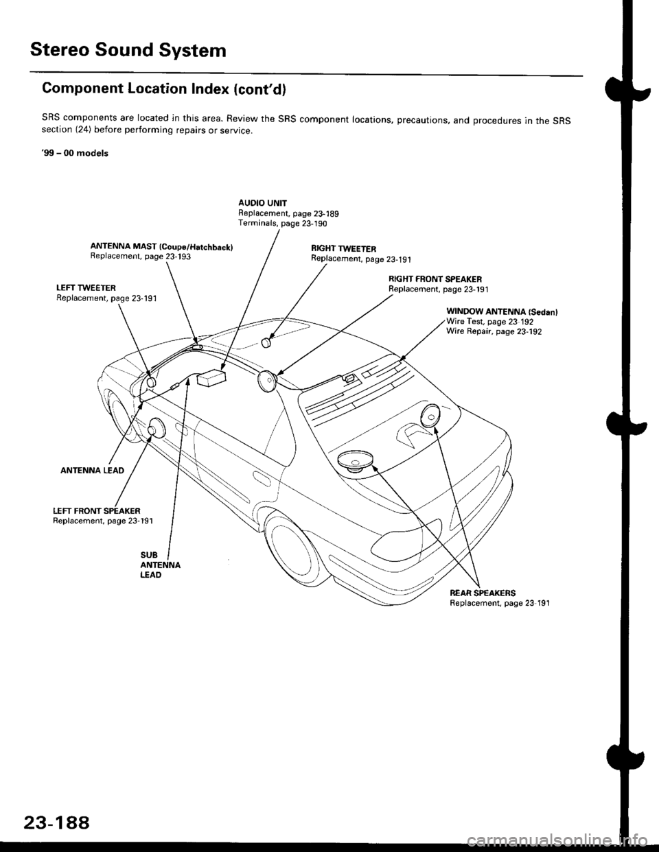
Component Location Index {cont'd)
SRS components are located ln this area. Review the SRS component locations, precautions, and orocedures in the sRSsection (24) before perlorming repairs or service.
'99 - 00 models
AUDIO UNITFeplacement, page 23-189Terminals, page 23-190
ANTENNA MAST (Coupe/Hatchbeck)Replacement, page 23,193RIGHT TWEETERReplacement, p6ge 23-191
LEFT TWEETERReplacement, page 23-191
ANTENNA LEAD
LEFT FRONTReplacement, page 23-191
RIGHT FRONT SPEAKERReplacernent, page 23-191
WINDOW ANTENNA {SedanlWire Test, page 23 192Wire Repair, page 23-192
SUB
I.TAO
REAR SPEAKERSReplacemont, page 23-191
23-1AA
Page 1721 of 2189
Power Door Locks
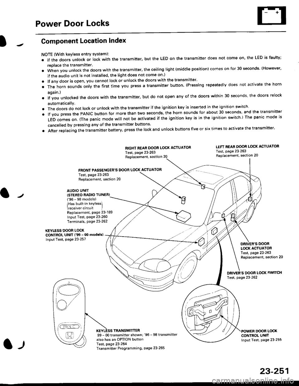
Component Location Index
NOTE (With keyless entry systeml:
. It the doors unlock or lock with the transmitter, but the LED on the transmitter does not come on, the LED is faulty;
replace the transmitter'
. when vou unlock the doors with the transmitter, the ceiling light (middle position) comes on for 30 seconds. (However,
if the audio unit is not installed, the light does not come on )
. lf any door is open, you cannot lock or unlockthe doors with the transmitter'
. The horn sounds only the first time you press a transmitter button. (Pressing repeatedly does not activate the horn
again.)
o lf vou unlocked the doors with the transmitter, but do not open any of the doors within 30 seconds, the doors relock
automatically.
. The doors do not lock or unlock with the transmitter if the ignition key is inserted in the ignition switch
. lf you press the PANIC button for more than two seconds, the horn sounds for about 30 seconds, and the transm'fer
LED comes on. (The panic mode will not be activated iJ the ignition key is in the ignition switch ) The panic mode is
cancelled by pressing any of the transmitter buttons'
o After replacing the transmitter battery, press the lock and unlock buttons five or six times to activate the transmitter'
Replacement, section 20
FRONT PASSENGER'S DOOR LOCK ACTUATOR
RIGHT REAR DOOR LOCK ACTUATOR
Test, page 23-263
I.IFT REAR DOOR LOCK ACTUATOR
Test, page 23 263Replacement, section 20
LOCK ACTUATORTest, page 23-263Replacement, section 20
ORIVER'S DOOR LOCK SWITCH
Test, page 23'262
DOOR L@XCONTROL UN]TInput Test, page 23 255
23-251
Test, page 23-263Replacement, section 20
AUDIO UNIT(STER€O RADIO TUNER)
{'96 - 98 models)
lHas built-in keylessl
eceiver circuit IReplacement, page 23-189
Input Test, page 23-260
Terminals, page 23-262
KEYLESS DOOR LOCKCONTROL UNIT l'99 - 00 modelsl
Input Test, Page 23-257
l-l
TRANSMITTER99 - 0O transmitter shown;'96 -98 transmifter
also has an OPTION buttonTest, page 23-264Transmitter Programming, page 23_265
Qi,,a/
/----
L(ru
i'.-8,-'l
/'-'6
Page 1728 of 2189
Power Door Locks
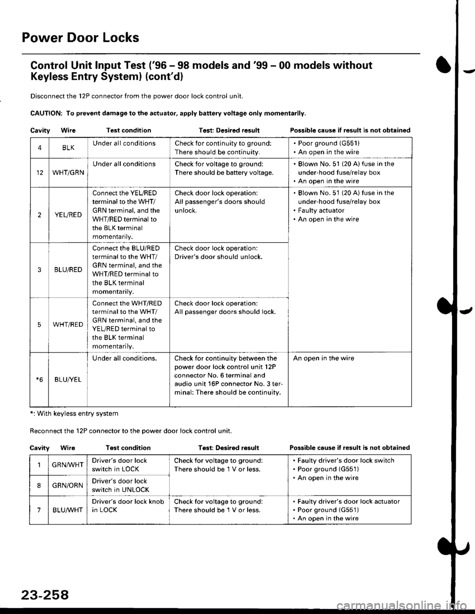
Control Unit lnput Test ('96 - 98 models and'99 - 00 models without
Keyless Entry Systeml (cont'dl
Disconnect the 12P connector from the power door lock control unit.
CAUTION: To prevsnt damage to the actuator, apply battery voltage only momentarily.
Cavity WireTest conditionTest: Desired resultPossible cause if result is nol obtained
*: With keyless entry system
Reconnect the 12P connector to the power door lock control unit.
Cavity WireTest conditionTssl: Desirsd losullPossible cause it resull b not obtained
4BLKUnder all conditionsCheck for continuity to ground:
There should be continuity.
. Poor ground (G55'l ). An open in the wire
WHT/GRN
Under all conditionsCheck for voltage to ground:
There should be battery voltage.
. Blown No. 51 (20 A)fuse in the
under-hood fuse/relay box. An open in the wire
2YEURED
Connect the YEURED
terminal to the WHT/
GRN terminal, and the
WHT/RED terminal to
the BLK terminal
momenraflty.
Check door lock operation:
All passenger's doors should
untocK.
Blown No. 51 {20 A) fuse in the
under-hood fuse/relay box
Faulty actuator
An open in the wire
3BLU/RED
Connect the BLU/RED
terminal to the WHT/
GRN terminal. and the
WHT/RED terminal to
the BLK terminal
momenraflry.
Check door lock operation:
Driver's door should unlock.
5WHT/RED
connect the WHT/RED
terminal to the WHT/
GRN terminal, and the
YEL/RED terminal to
the BLK terminal
momenrafl ty.
Check door lock operation:
All passenger doors should lock.
BLU/YEL
Under all conditions.Check for continuity between the
power door lock control unit l2P
connector No. 6 terminal and
audio unit 16P connector No. 3 ter-
minal: The.e should be continuity.
An open in the wire
GRN,ryVHTDriver's door lock
switch in LOCK
Check for voltage to ground:
There should be 1 V or less.
Faulty driver's door lock switch
Poor ground {G551)
An open in the wire
8GRN/ORNDriver's door lock
switch in UNLOCK
7BLUA/VHT
Driver's door lock knob
in LOCK
Check for voltage to ground:
There should be 1 V or less.
Faulty driver's door lock actuator
Poor ground {G551)
An open in the wire