Page 1732 of 2189
Power Door Locks
Audio Unit {Keyless Receiver Circuitl Input Test ('96 - 98 models}
Remove the audio unit, then disconnect the A and B connectors (see page 23-189).
Inspect the connector and socket terminals to be sure they are all making good contact
. lf the terminals are bent, loose or corroded, repair them as necessary, and recheck the system
. lf the terminals look OK, make the following input tests at the connector.
- lf anv test indicates a problem, find and correct the cause, then recheck the system
lf all the inout tests prove OK, the control unit must be faulty; replace it.
A CONNECTOBB CONNECTOR
16P CONNECTORS
AUDIO UNIT
L
2.
WHT/BLU YEL/RED
{KEYLESS RECEIVER CIRCUIT}
23-262
Page 1734 of 2189
Power Door Locks
Audio Unit lKeyless Receiver
Circuitl Terminals ('96 - 98 modelsl
CavityWireDestination
16P CONNECTOR
B1BLU/REDlgnition key switch
*82LT GRNTrunk latch switch
Ft2BLU/YELUnlock (Driver's door)
B4BLUValet switch
*85LT BLUSecurity {lN)
B6BLK/YE LNo. 14 (7.5 A) fuse
*81ORNSecurity (D2)
B8LT GRN/BLKCeiling light
B9GRN/ORNUnlock (All doors)
810GRNA/VHTLock (OutPutl
*811BLU/WHTLED O
*812WHT/BLKSecurity (D0)
+B 13YEL/BLUSecurity (D'l )
814LT GRN/REDDoor switch
B15BLKG round (G401, G402)
o toGRYnorn
*: For security system (option)
23-264
Driver's Door Lock Switch Test
1. Remove the inner handle (see section 20).
2. Disconnect the 3P connector from the door lock
switch.
Check for continuity between the terminals in each
switch position according to the table.
DRIVER'SDOORLOCKswtTcH
Terminal
Position123
LOCKo-----o
OFF
UNLOCKo----o
Page 1737 of 2189

)
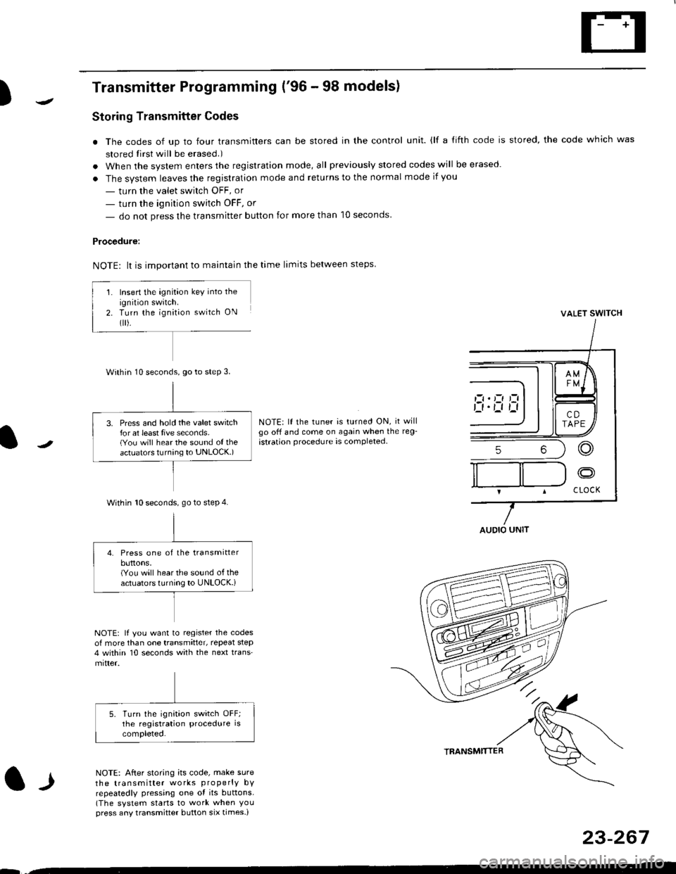
Transmitter Programming ('96 - 98 models)
Storing Transmitter Codes
. The codes of up to four transmitters can be stored in the control unit. {lf a {ifth code is stored, the code which was
stored tirst will be erased.)
. When the system enters the registration mode, all previously slored codes will be erased.
. The system leaves the registration mode and returns to the normal mode if you
- turn the valet swirch OFF, or
- turn the ignition switch OFF, or
- do not press the transmitter button for more than 10 seconds
Procedure:
NOTE: lt is important to maintain the time limits between steps
VALET SWITCH
NOTE: lf the tuner is turned ON, it willgo off and come on again when the reg-
istration procedure is completed-
l-l
NOTE: lf you want to register the codesof more than one transmitter, repeat step4 within 10 seconds with the next trans'mitter.
NOTE: After storing its code, make sure
the transmitter works properly bYrepeatedly pressing one ot its buttons.(The system starts to work when Youpress any transmitter button six times-)
TRANSMTITTER
23-267
--
Insert the ignition key into the
ignition swatch.Turn the ignit;on switch ON
flr).
Within 10 seconds, go to steP 3.
3. Press and hold the valet switchfor at least tive seconds.(You will hear the sound of theactuators turnang to UNLOCK.)
Within 10 seconds. go to step 4.
4. Press one of the transmitterbuttons,(You will hear the sound of theactuators turning to UNLOCK.i
AUDIO UNIT
Page 1836 of 2189
- Under-dash Fuse/Relay Box (cont'd)
Fuse/Relay I nformation
Fuse
NumberFuse NameAmps
(P/W RELAY)
(S/R RELAY)
FR WIPER
FR WASHER
LO
Page
10-7 |
I
Component or Clrcuit Protected
i Power window relay, Moonrool
Front wioer/washer
CIGARETTE
LIGHTER
ACC SOCKET
10-7Accessory power socket
I RAD|O CLOCK
I
110 115)l
tl
1O-7 |
I
Stereo radio tuner ('96198 models), Audio unit ('99100
model)
Not used
i 7.5i 114 iDash & console lights
I srnnrensrorunl | 7.slzl , zt -t , ! eCU-n main retay, PCM/ECM, Integrated controt unit
I ot 21-2 t
I LICENSE LIGHTS I 7.5
I rerr uesls I
Parking lights, License plate lights, Tail lights| 1oo-1 |
tl
| (f NTERLOCK UNIT) | 7.5 | 10-12 I Interlock system
* = '98 models
6-2
Page 1839 of 2189
Fuse
NumberFuse NameAmpsPage
BATTERY
Component or Circult Protected
Power distribution
lgnition switch
INTERIOR LIGHT | 7.5 | 10-10 | DLC, Ceiling light, Trunk light
FI E/M15 i(20 GX) i
i PGM-FI main relay, Fuel injection relay (GX)
Not used
POWER WINDOW| 10-10 | Power window relay
BACK UPStereo radio iuner ('9G'98 mod€ls), Audio unit ('99100
models), Heater control panel, PCM/ECM, TCM (9e'98
cvr)
HEADLIGHT
REAR DEFROSTER I
DOOR LOCK UNIT,
ROOF
i 10-12i Headlights
Not used
Rear window defogger relay
Power door lock control unit (all except '99-'00 models
with keyless), Keyless door lock control unit ('99-'00
models with keyless), Moonroof
i HORN, SrOP Lri 10-13i Horn relay, Brake switch
HAZARDHazard warning switch
OPTIONI 10-13I Security system (option)
i HEATER MOTOR Ii 10-1 i Blower motor relay
(CONDENSER FAN)
COOLING FANl1o-1
Condenser Jan relay, A'lC compressor clutch relay
Radiator tan relay
&5
Page 2139 of 2189

Connector Views (cont'd)
72. C1s0 (GX Model)
1 YEUBLU (PGM-FI)
2 GRN/BLK (PGM.FD
3 LT GRN (A/t controls)
4 YEURED (PGM-FD
5 GRN/rEL (PG|\,1-FD
- Light green- Left rear of engine compartment- Connects engine wire harness to main wire harness
6
7
BLU/IEL (PGM-FD
Male - PNKFemale - GRN(4,/T convols)
YEL (A,/T controls)
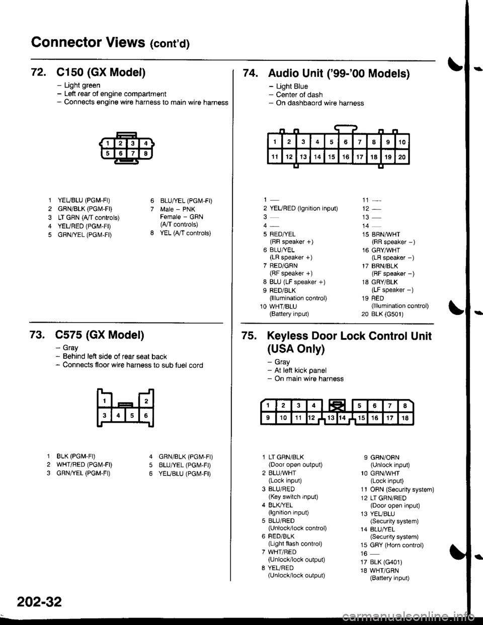
74. Audio Unit ('99-'00 Models)
- Light Blue- Center ol dash- On dashbaord wire harness
2 YEURED (lgnition input)
5 RED/YEL(RF speaker f)
6 BLU/YEL(LR speaker +)
7 RED/GRN(BF speaker +)
I BLU (LF speaker +)
9 RED/BLK(lllumination control)
10 WHT/BLU(Battery input)
']]]-
12*
14
15 BRN,^/VHT
{RR speaker -)
16 GRYAVHT(LR speaker -)
17 BRN/BLK(RF speaker -)
18 GRY/BLK
{LF speaker -)
19 RED(lllumination control)
20 BLK (G501)
73. C575 (GX Model)
BLK (PGM.FD
WHT/RED (PGI\4-FD
GRN/YEL (PGM.FI)
- Gray- Behind left side of rear seat back- Connects floor wire harness to sub luel cord
5
1
2
3
GRN/BLK (PGr\4-Fr)
BLU/YEL (PGI\'-FD
YEUBLU (PGI\,4,FD
202-32
75. Keyless Door Lock Control Unit
(USA Only)
- Gray- At lett kick panel- On main wire harness
l LT GRN/BLK(Door open output)
2 BLU,ryVHT(Lock input)
3 BLU/RED(Key switch input)
4 BLK/YEL(lgnition input)
5 BLU/RED(Unlock/lock control)
6 FED/BLK(Light flash control)
7 WHT/RED(Unlock/lock output)
8 YEURED(Unlock/lock output)
9 GRN/ORN(Unlock input)'10 GRNA/VHT(Lock input)
11 ORN {Securiiy system)
12 LT GRN/RED
{Door open input)
13 YEUBLU(Security system)
14 BLU/YEL(Security system)
15 GRY (Horn control)
17 BLK (G401)
18 WHT/GRN(Battery input)
Page 2168 of 2189

)\
) -,
.'
'1: With shift-up indicator or cruise control system ('96-'97 models)
With cruise control system ('98-'00 models)
.2: '96198 models.3: '99-'00 models
c5o9 csrr c510 c515
13 1c517
DISHAOABD w|REIIARNESS
Connector
or
Terminal
Number of
Cavities/
Color
LocationConnects toNotes
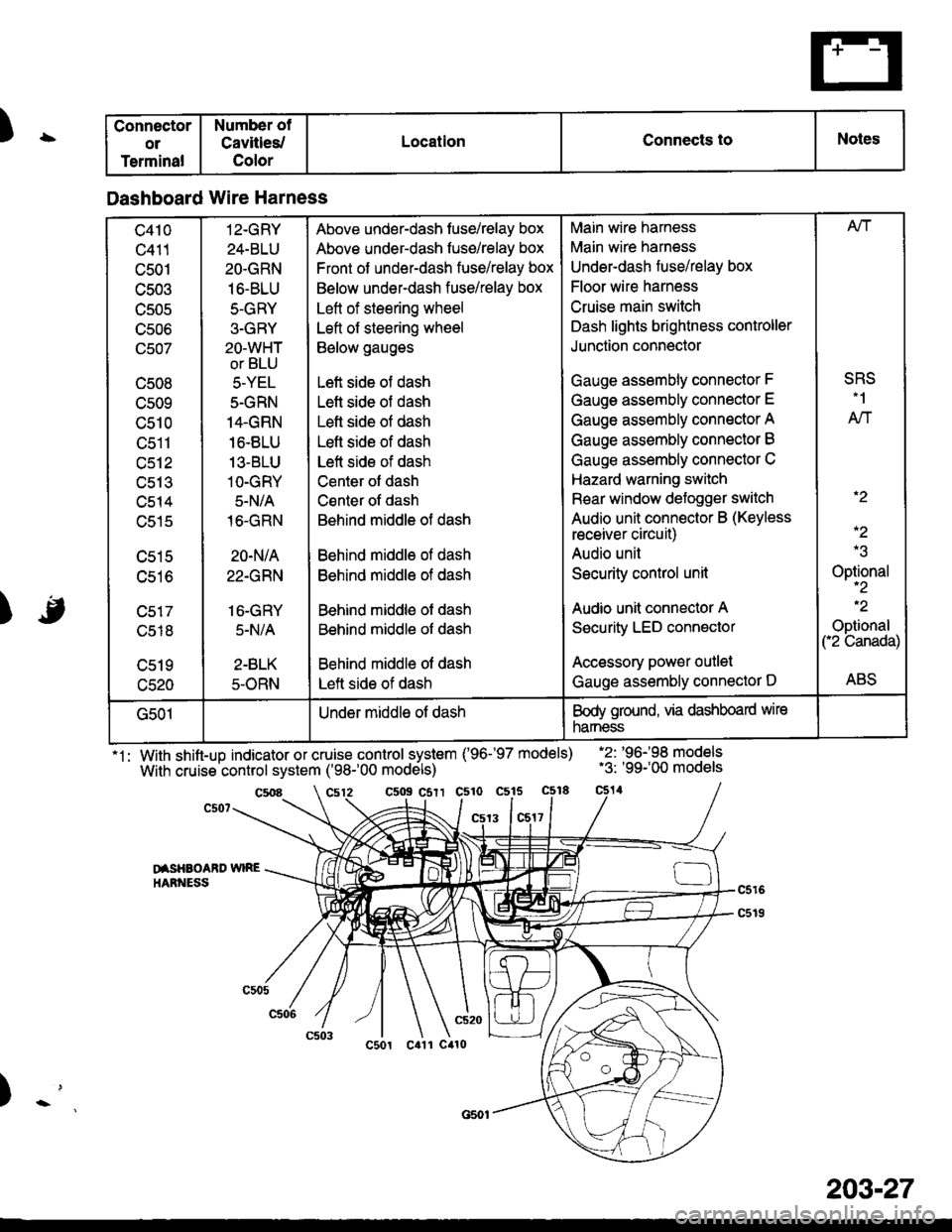
Dashboard Wire Harness
c410
c411
c501
c503
TJJUC
UCUO
(Jcu/
c508
cs09
c510
tJctl
c512
uc t.t
c514
c515
c516
c518
c520
12-GRY
24-BLU
2O.GRN
16-BLU
5-GRY
3-GRY
2O-WHT
or BLU
5-YEL
5-GRN
14.GRN
16.8LU
13-BLU
1O-GRY
5-N/A
16-GRN
20-N/A
22.GRN
16-GRY
5.N/A
2-BLK
5-ORN
Above under-dash fuse/relay box
Above under-dash fuse/relay box
Front of under-dash fuse/relay box
Below under-dash fuse/relay box
Left of steering wheel
Left of steering wheel
Below gauges
Left side of dash
Lett side of dash
Left side of dash
Lefl side of dash
Left side of dash
Center ot dash
Csnter of dash
Behind middle of dash
Behind middle ol dash
Behind middle of dash
Behind middle of dash
Behind middle of dash
Behind middle of dash
Left side of dash
Main wire harness
Main wire harness
Underdash fuse/relay box
Floor wire harness
Cruise main switch
Dash lights brightness controller
Junction connector
Gauge assembly connector F
Gauge assembly connector E
Gauge assembly connector A
Gauge assembly connector B
Gauge assembly connector C
Hazard warning switch
Rear window defogger switch
Audio unit connector B (Keyless
receiver circuit)
Audio unil
Security control unit
Audio unit connector A
Security LED connector
Accessory power outlet
Gauge assembly connector D
Afi
SRS.1
AN
.2
-2
Optional-2
.2
Optional("2 Canada)
ABS
G501Under middle of dashBody ground, via dashboard wire
narness
203-27