1997 HONDA CIVIC iso connectors
[x] Cancel search: iso connectorsPage 37 of 2189
Llo
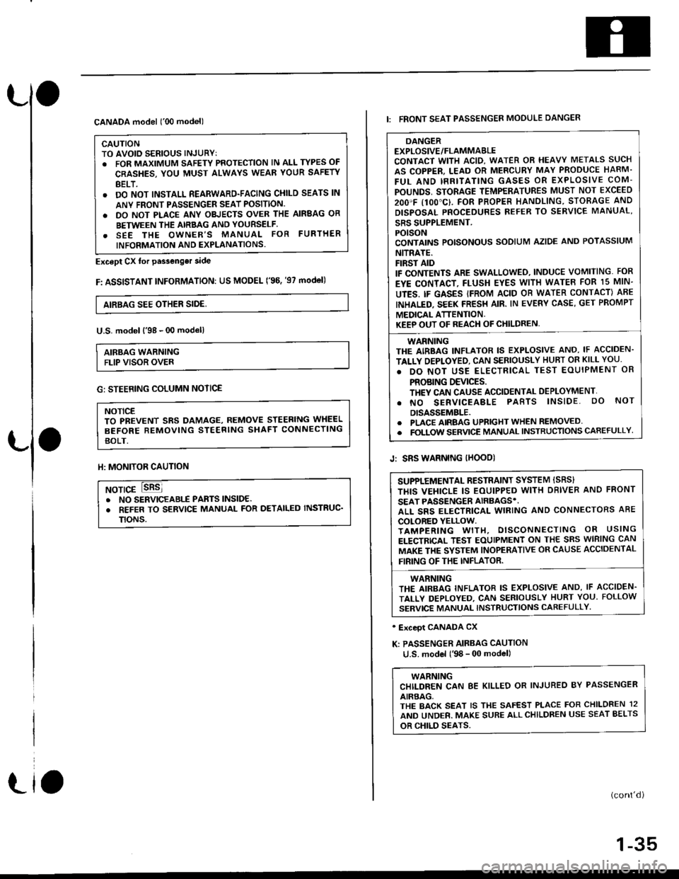
CANADA model ('00 model)
CAUTIONTO AVOID SERIOUS INJURYT. FOR MAXIMUM SAFETY PROTECTION lN ALL TYPES OF
CRASHES, YOU MUST ALWAYS WEAR YOUR SAFETY
BELT.. DO NOT INSTALL REARWARD-FACING CHILD SEATS lN
ANY FRONI PASSENGER SEAT POSITION.
. DO NOT PLACE ANY OBJECTS OVER THE AIRBAG OR
BETWEEN THE AIRBAG AND YOURSELF.. SEE THE OWNER'S MANUAL FOR FURTHER
INFORMATION AND EXPLANATIONS.
Except Cx tor passenger side
F: ASSISTANT INFoRMATION: US MODEL ('96. '97 mod€l)
AIRBAG SEE OTHER SIDE,
U.S. model l'98 - 00 modell
AIRBAG WARNINGFLIP VISOR OVER
Llo
G: STEERING COLUMN NOTICE
NOTICETO PBEVENT SRS DAMAGE, REMOVE STEERING WHEEL
BEFORE REMOVING STEERING SHAFT CONNECTING
BOLT.
ll: MONITOR CAUTION
NOTICE. NO SERVICEABIf PABTS lNSlDE.. REFER TO SERVICE MANUAL FOR DETAILED INSTRUC'
TtoNs.
DANGEREXPLOSIVE/FLAMMABLECONTACT WITH ACID, WATER OR HEAVY METALS SUCH
AS COPPER, LEAD OR MERCURY MAY PRODUCE HARM.
FUL AND IRRITATING GASES OR EXPLOSIVE COM-
POUNDS, STORAGE TEMPERATURES MUST NOT EXCEED
2OO'F I1OO"C}. FOR PROPER HANOLING, STORAGE AND
DISPOSAL PNOCEDURES REFER TO SERVICE MANUAL'
SRS SUPPLEMENT.POISONCONTAINS POISONOUS SODIUM AZIDE AND POTASSIUM
NITRATE.FIRST AIDIF CONTENTS ARE SWALLOWEO, INDUCE VOMITING. FOR
EYE CONTACT, FLUSH EYES WITH WATEB FOR 15 MIN-
UTES. IF GASES IFROM ACID OB WATER CONTACT) ABE
INHALED. SEEK FRESH AIR. IN EVERY CASE, GET PROMPT
MEDICAL ATTENTION.KEEP OUT OF REACH OF CHILDREN,
WARNINGTHE AIRBAG INFLATOR IS EXPLOSIVE AND, IF ACCIDEN-
TALLY OEPLOYED, CAN SERIOUSLY HUBT OR KILL YOU.
. DO NOT USE ELECTRICAL TEST EOUIPMENT OR
PROBING DEVICES.TH€Y CAN CAUSE ACCIDENTAL DEPLOYMENT'
. NO SERVICEABLE PABTS lNSlDE. oO NoT
DISASSEMBLE.. PLACE AIRBAG UPRIGHT WHEN REMOVED. FOLTOW SERVICE MANUAL INSTRUCTIONS CAREFULLY
I: FRONT SEAT PASSENGER MOOULE DANGER
Jr SRS WARNING IHOOD)
' Exceot CANADA CX
K: PASSENGER AIRBAG CAUTION
u.S. model l'98 - 00 model)
WARNINGCHILDREN CAN 8E KILLED OR INJUREO BY PASSENGER
AIRBAG,THE BACK SEAT IS THE SAFEST PLACE FOR CHILDREN 12
AND UNDER. MAKE SURE ALLCHILDREN USE SEAT BELTS
OR CHILD SEATS.
(cont'd)
1-35
SUPPLEMENTAL RESTRAINT SYSTEM ISRS}
THIS VEHICLE IS EOUIPPED WITH DBIVER AND FRONT
SEAT PASSENGER AIRBAGS'.ALL SRS ELECTRICAL WIRING AND CONNECTORS ABE
COLORED YELLOW.TAMPERING WITH, DISCONNECTING OR USING
ELECTRICAL TEST EOUIPMENT ON THE SRS WIRING CAN
MAKE THE SYSTEM INOPERATIVE OR CAUSE ACCIDENTAL
FIRING OF THE INFLATOR.
WARNINGTHE AIRBAG INFLATOR IS EXPLOSIVE AND, IF ACCIDEN.
TALLY DEPLOYED, CAN SERIOUSLY HURT YOU. FOLLOW
SERVICE MANUAL INSTRUCTIONS CAFEFULLY'
Page 177 of 2189
Removal
Engine removal is not required for this procedure.
!@@ Make sure jacks and safety stands are placed
properly and hoist brackels are attached to correst posi-
tion on the engine,
CAUTION:
o Use fender covers to avoid damaging painted sur-
faces.
To avoid damage, unplug the wiling connectors
carelully while holding the connector portion.
To avoid damaging the cylinder head, wait until the
engine coolant temperature drops below 100"F {38'Cl
before loosening the retaining bolt.
NOTE:
. Unspecified items are common.
. Mark all wiring and hoses to avoid misconnection.
AIso, be sure that they do not contact other wiring or
hoses or interfere with other parts.
o Inspect the timing belt before removing the cylinder
n eao.
. Turn the crankshaft pulley so that the No. 1 piston is
at top dead center (see page 6-64).
1. Disconnect the negative terminal from the battery.
Drain the engine coolant {see page 10-7).
. Remove the radiator cap to speed draining.
Remove the strut brace (see page 5-2).
Remove the intake air duct and air cleaner housing
(see page 5-3).
Remove the adjusting bolt and mounting bolt, then
remove the power steering (P/S) pump belt and pump
(see page 5 5).
2.
3.
4.
\
ADJUSTING
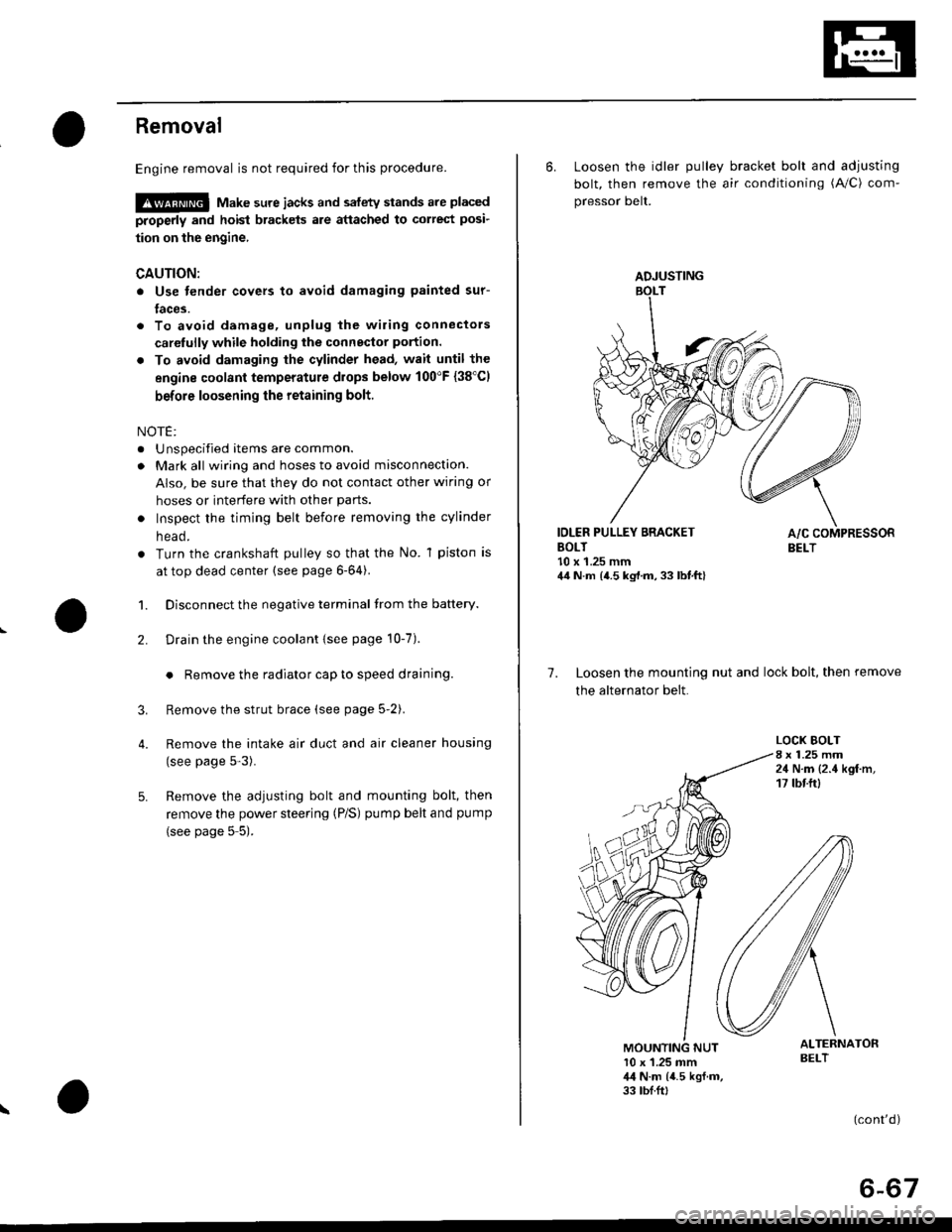
6. Loosen the idler pulley bracket bolt and adjusting
bolt, then remove the air conditioning (A/C) com-
pressor belt.
IDLER PULLEY BRACKETBOLT10 x 1.25 mm44 N.m {4.5 kg,l.m, 33 lbt.ft}
7. Loosen the mounting nut and lock bolt, then remove
the alternator belt.
LOCK BOLT8 x 1.25 mm24 N.m {2.4 kgf.m,17 tbtftl
ALTERNATORBELT10 x 1.25 mm,l,l N.m {4.5 kgf.m,33 tbf.ft,
(cont'd)
6-67
Page 1409 of 2189
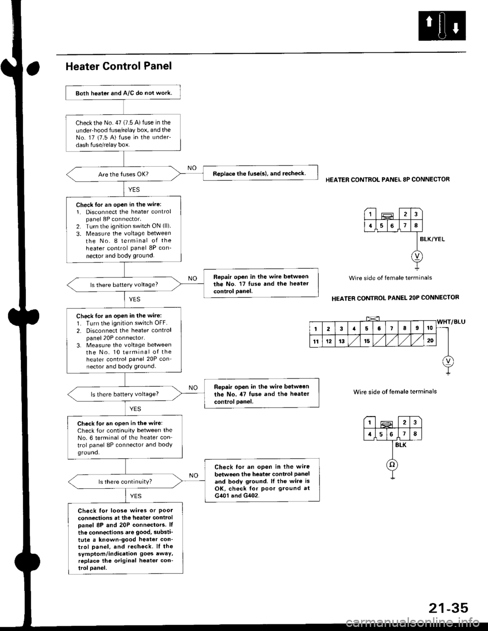
Both heater and A/C do nol work.
checkthe No.47 (7.5 A)fuse in the
under-hood fuse/relay box, and theNo. 17 {7.5 A) fuse in the under-
dash fuse/relay box.
ReDlace the tuse{s), and recheck.
Check lor an open in the wire:
1. Disconnect the heater controlpanel 8P connector,2. Turn the ignition switch ON (ll).
3. Measure the voltage between
the No. I terminal of the
heater control panel 8P con-
nector and body ground.
Repair open in the wire betweenthe No. '17 luse and th6 heatercontrol oanel,ls there battery voltage?
Check for an open in the wire:
1. Turn the ignition switch OFF.
2. Disconnect the heater controlpanel20P connector.3. Measure the voltage lletweenthe No. 10 terminal of theheater control Panel 20P con-nector and body ground.
Repair op6n in the wir€ between
the No. il7 tuse and the heater
controloanel,ls there battery voltage?
Check for an open in the wite:Check for continuity between theNo. 6 terminal of the heater con
trol panel 8P connector and bodyground.
Ch6ck tor an open in lhe wire
betwoen the heator control Paneland bodv ground. lf the wire isOK, check for poor ground atG401 and G402.
ls there continuity?
Check for looso wires or Poolconneciions at the heater controloanel 8P and 20P connectors. lf
the connections are good, substi'
tute a known-good heat€r con-trol Danel, and recheck. lI thesymptom/indication goes awaY,r6place the original h€ater con-troloanel.
HEATER CONTROL PANEL 8P CONNECTOR
BLK/YEL
Wire side of female terminals
HEATER CONTROL PANEL 2OP CONNECTOR
Wire side of temale terminals
I2
1578
BLK
o
1
4I
v
Page 1438 of 2189
![HONDA CIVIC 1997 6.G Workshop Manual Troubleshooting
Compressor lcontdl
COMPRESSOR CLUTCH RELAY4P SOCKET
l--;l
12 |---r--]l.l3 |L-J--J
] BLK/YEL
A(v)
!
ECM/PCM CONNECTOR A I32P}
Wire side of female terminats
*Howto use the backprobe set HONDA CIVIC 1997 6.G Workshop Manual Troubleshooting
Compressor lcontdl
COMPRESSOR CLUTCH RELAY4P SOCKET
l--;l
12 |---r--]l.l3 |L-J--J
] BLK/YEL
A(v)
!
ECM/PCM CONNECTOR A I32P}
Wire side of female terminats
*Howto use the backprobe set](/manual-img/13/6068/w960_6068-1437.png)
Troubleshooting
Compressor lcont'dl
COMPRESSOR CLUTCH RELAY4P SOCKET
l--;l
12 |---r--]l.l3 |L-J--J
] BLK/YEL
A(v)
!
ECM/PCM CONNECTOR A I32P}
Wire side of female terminats
*Howto use the backprobe setsConnect the backprobe adapters to the stackang patch cords, andconnect the cords to a multimeter. Using the wire insulation as aguide for the contoured tip of the backprobe adapter, gently slidethe tip into the connector from the wire side until it comes in con-tact with the terminalend ofthe wire (see section 11).
Frcm page 22-12
To page 22-15
Check Ior an open in the wire;1. Disconnecl the jumper wire.2. Turn the ignition swatch ON (ll).
3. l\4easure the voltage betweenthe No. 4 terminal of the com-pressor clutch relay 4P socketand body ground.
Repair open in the wire betw€enthe No. 17 fuso and the compres-sor clutch relav.
Check for an open in the wira:1. Turn the ignition switch OFF,then reinstall the compressorclutch relay.2. Make sure the A/C switch isOFF, then turn the ignitionswitch ON (ll).
3. Using a *Backprobe Set (T/N07SAZ 0010004), measurethe voltage between the No.17 terminal oI the ECM/PCMconnector A (32P) and bodyground with the ECM/PCMconnectors connected.
Repair open in the wirc betweonthe compressor clutch relay andthe ECM/PCtvt.
ls there battery voltage?
Page 1440 of 2189
Troubleshooting
Gompressor (cont'dl
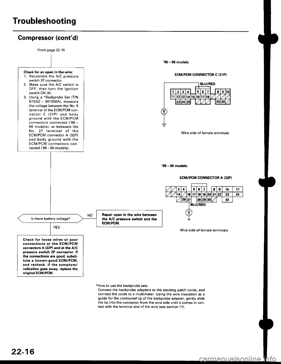
'96 -98 models:
ECM/PCM CONNECTOR C 13lPI
Wire side ot female terminals
'9!t - 00 mod.bi
ECM/PCM CONNECTOR A I32P)
Wire side ot female terminals
*How to use the backprobe setsConnect the backprobe adapters to the stacking patch cords, andconnect the cords to a multimeter. Using the wire insulation as aguide for the contoured tip of the backprobe adapter, gently slidethe tip into the connector from the wire side until it comes in con-tact with the terminal end ofthe wire {see section 11}.
From page 22-15
Check for an open in thg wire:'1. Reconnect the A"/C pressure
switch 2P connector.2. Make sure the A/C switch isOFF, then turn the ignitionswitch ON (ll).
3. Using a *Backprobe Set {T/N07SAZ - 001000A), measurethe voltage between the No. 5terminal of the ECM/PCM con-nector C (31P) and bodyground with the EcM/PcMconnectors connected ('96 -
98 models), or between theNo. 27 terminal of theECM/PCM connector A (32P)
and body ground with theECM/PCM connectors connected ('99 - 00 models).
Rapdir open in tho wi?e botwaonthe A/C pr..-ruro lwitch rnd th.ECM/PCM.
Check lor loo3e wires or ooolconnections at the ECM/PCMconnectoB A l32P) and at the A/Cpressure switch 2P connector, lfthe connections are good, substi-tute a known-good ECM/PCM,and recheck. lf the svmptom/indication goos away, repbce theoriginal ECM/PCM.
31501E91011
tat6l11E1921222321
BLU/RED
22-16
Page 1697 of 2189
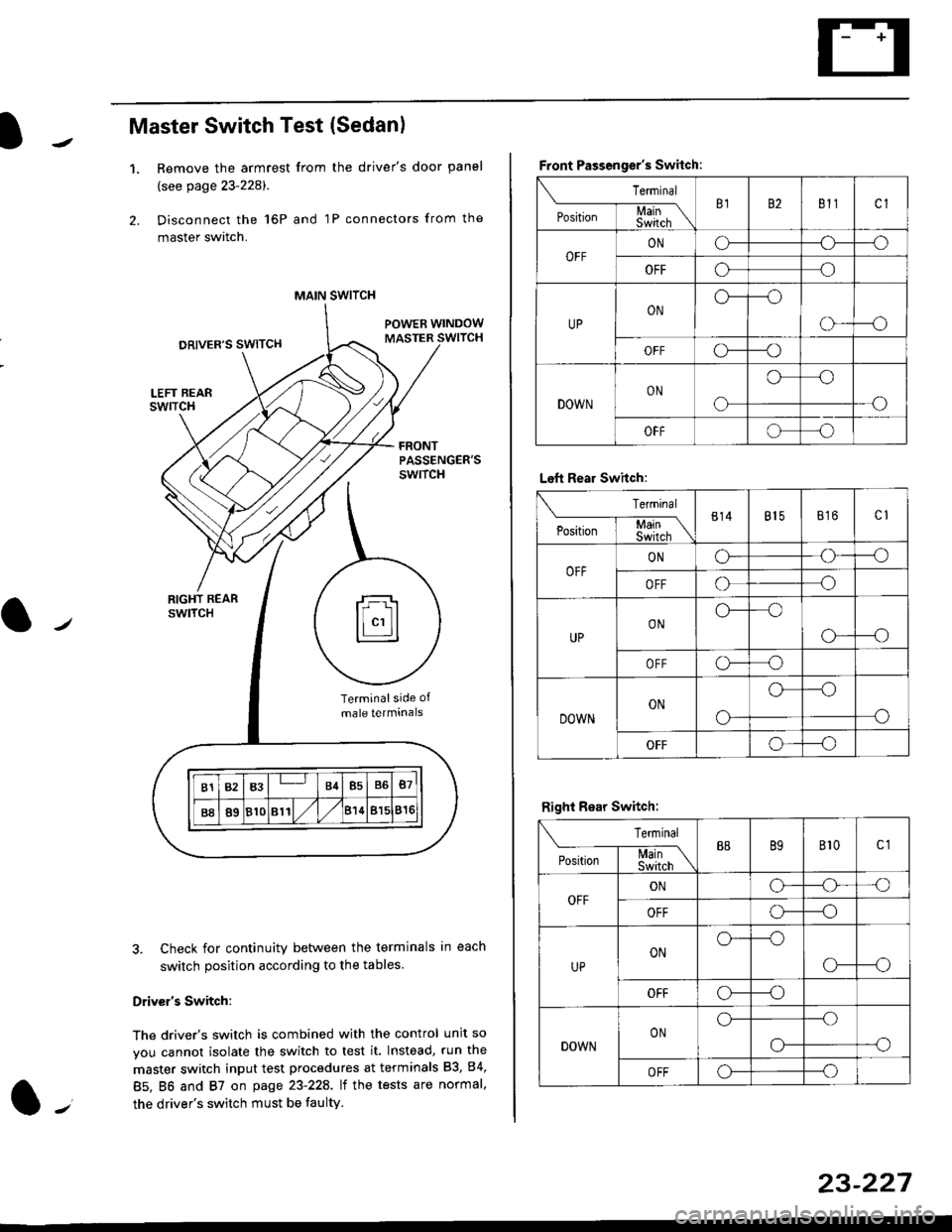
Master Switch Test (Sedan)
1.Remove the armrest from the driver's door panel
(see page 23-228).
Disconnect the 16P and 1P connectors from the
master switch.
Check for continuity between the terminals in each
switch position according to the tables
Driv€r's Switch:
The driver's switch is combined with the control unit so
you cannot isolate the switch to test it. Instead, run the
master switch input test procedures at terminals 83, 84,
85. BO and 87 on page 23-22A. lt the tests are normal,
the driver's switch must be faulty.
MAIN SWITCH
rFl
ll"'llt.:::::::l
B1B3B4B5B6B7
B889810811/l/leuBl5816
Terminalside of
male terminals
Front Passenger's Switch:
Terminal
P*,j--f$t,l"\B182811cl
OFFONCF--o
OFFooo
UPONo---o
o---o
OFFc\---o
DOWNON
o
oo
-o
OFFoo
Left Rear Swhch:
Terminal
P".r,-'-f-mn\814815816c1
OFFONG--o
OFFoo
UPONo--oo
o---o
OFFo-o
DOWNON
o-
o--o
o
OFFo--_o
Right Rear Switch:
Terminal
'**-T-*mB889B'�t0c1
OFFONo-o'o
OFFo---o
UPONo---o
CF--o
OFFCr---o
DOWNONo---.o
--oo-
OFFo---o
23-227
Page 1823 of 2189
How To Use This Manual
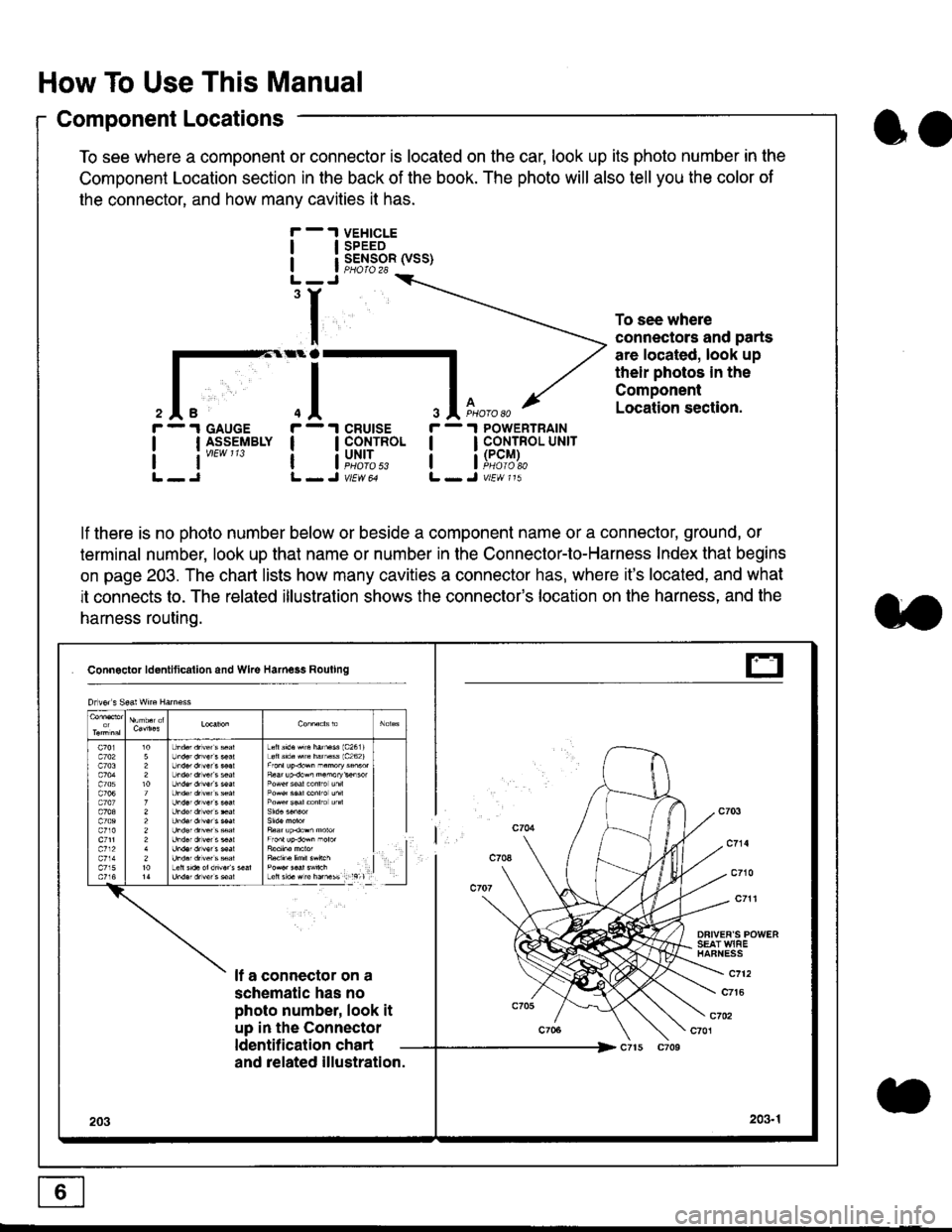
Component Locations
To see where a component or connector is located on the car, look up its photo number in the
Component Location section in the back of the book. The photo will also tell you the color of
the connector, and how many cavities it has.
To see where
connectors and parts
are located, look up
their photos in the
Component
Location section.
I
I
3
r - 1 GAUGE
| | I_S-9_EIBLY
lt''""'
r - 1 cRUtsE
! !fi':*
r - 1 POWERTRAIN
I I CONTROL UNrr
a i[i9#r,
lf there is no photo number below or beside a component name or a connector, ground, or
terminal number, look up that name or number in the Connector-to-Harness Index that begins
on page 203. The chart lists how many cavities a connector has, where it's located, and what
it connects to. The related illustration shows the connector's location on the harness, and the
harness routing.
Connactor ldontlticallon and Wke Harness Rouling
DFIVEF'S POWERSEAT WIAEHAFNESS
It a connector on a
schematic has no
photo number, look it
up in the Connector
ldentilication chart
c712
c7t6
c702c701
and related illustration.
203203.1
Drlvor s Sea! wne Harn€ss
Lefts'd.Hrc hatu$ 1c2611Loft s'd. src hamass 1c262)
F6ar up.dow^ n.morykisor
l
E
oo