1997 HONDA CIVIC Bushing
[x] Cancel search: BushingPage 58 of 2189
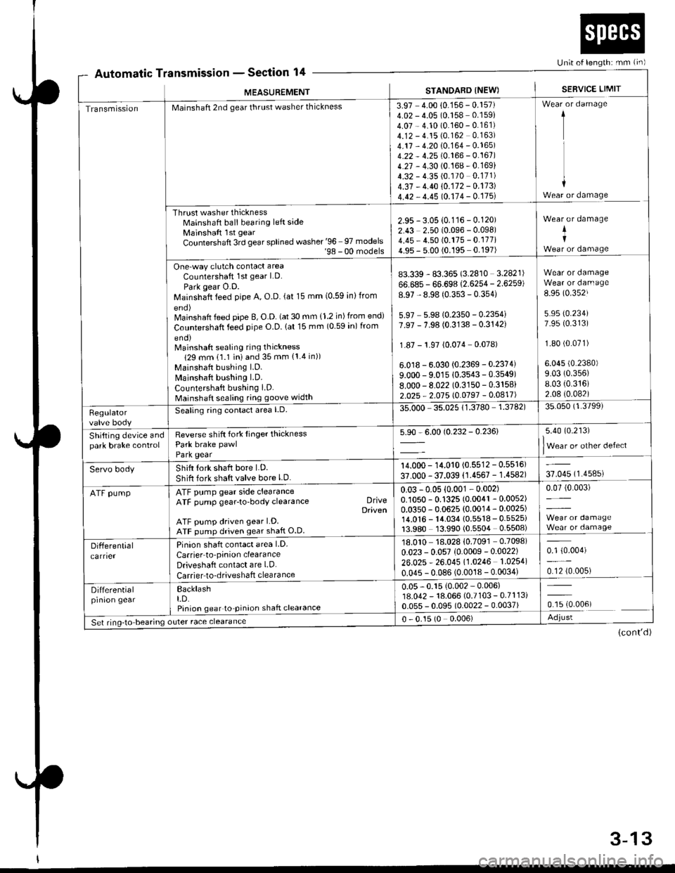
Automatic TnsmtsstonSection 14Un;t of length: mm {in)
r
MEASUREMENT
a
STANDARD INEW)SEBVICE LIMIT
TransmissionMainshaft 2nd gear thrust washer thickness
Thrust washer thicknessMainshaft ball bearing left sideMainshaft lst gear
Countershaft 3rd gear splined washer '96 97 models'98 - 00 models
One-way clutch contact area
Countershaft 1st gear LD.
Park gear O.D.Mainshaft feed pipe A, O.D. (at 15 mm (0.59 inlfrom
Mainshaft feed pipe B, O.D. (at 30 mm {1.2 in) from end)
Countershaft feed pipe O.D. lat 15 mm (0 59 in) from
eno)Mainshaft sealing ring thickness
129 mm 11.1 iniand 35 mm {1.4 in))
Mainshaft bushing l.D.
Mainshaft bushing LD.
Countershaft bushing LD.Mainshaft sealing ring goove width
3.97 4.00 10.156 - 0.157)4.02 - 4.05 (0.158 0.159)
4.07 - 4.10 (0.160 - 0.161)4.12 - 4.15 (0.162 0.163)
4.17 - 4.20 10.164 - 0.165)4.22 - 4.25 (0.166 - 0.167)4.27 - 4.30 (0.168-0.169)
4.32 - 4.35 (0.170 0.171)
4.37 - 4.40 10.172 - 0.173)
4.42 - 4.45 10.114 - 0.175l
1
I
+Wear or damage
2.95 - 3.05 {0.116 - 0.120)2.43 2.50 (0.096 - 0.098)4.45 - 4.50 (0.175 - 0.177i4.95 - 5.00 (0.195 0.197)
Wear or damage
+I
83.339 - 83.365 (3.2810 3.2821)
66.685 - 66.698 (2.6254 - 2.6259)
8.97 - 8.98 (0.353 - 0.354)
5.97 5.9810.2350 - 0.2354i7.97 - 7.98 (0.3138 - 0.3142)
1.87 - 1.97 {0.074 0.078)
6.0 r8 - 6.030 {0.2369 - 0.2374)
9.000 - 9.01s 10.3543-0.3549)8.000-8.022 (0.3150 - 0.3158)
2.025 - 2.015 l0.0197 -0.0417)
Wear or damageWear or darn age
8.95 (0.352J
5.95 (0.234)
7.95 (0.313)
1.80 (0.071)
6.045 (0.2380)
9.03 (0.356)
8.03 {0.316)2.08 (0.082)
Regulatorvalve body
Seating ring conlact area l.D.35.000 35.02511.3780 1.3782)35.050 (1.3799)
Shifting device andpark brake controlReverse shift fork Iinger thicknessPark brake pawl
Park gear
5.90 - 6.00 (0.232 - 0.236)5.40 (0.213)
lWear or other defect
Servo bodyShift fork shaft bore LD.
Shift fork shaft valve bore l.D.
14.000 - 14.010 (0.5512 - 0.5516)
37.000 - 37.039 (1.4567 - 1.4582)37.045 (1.4585)
ATF pumpATF pump gear side clearanceATF pump gear-to-body clearance DriveDaiven
ATF pump driven gear LD.ATF pump driven gear shaft O.D
0.03 -0.05 {0.001 - 0.002)0.1050 - 0.1325 (0.0041 - 0.0052)
0.0350 - 0.0625 (0.0014 - 0.0025)14.0'�|6 - 14.034 {0.5518 - 0.5525i13.980 13.990 (0.5504 0.5508)
0.07 (0.003)
Differentialcarrier
Pinion shaft contact area LD.
Carrier to'pinion clearanceDriveshaft contact are LD.
Carrier to-driveshaft clearance
18.010 18.028 {0.7091 0.7098)
0.023 - 0.057 (0.0009 -0.0022)
26.025 * 26.045 11.0246 1.0254)
0.045 - 0.086 (0.0018 - 0.0034)
0.1 {0.004)
0.12 {0.005)
Differentialprnron gearBacklasht.D.Pinion gear to-pinion shaft clearance
0.05 - 0.15 {0.002 - 0.006)18.042 - 18.066 (0.7103 - 0.7113i0.055 - 0.095 (0.0022 - 0.0037)ffi.oour
Set ring-to bearing outer race clearance0 - 0.15 (0 0.006)Adjust
(cont'd)
3-13
Page 60 of 2189
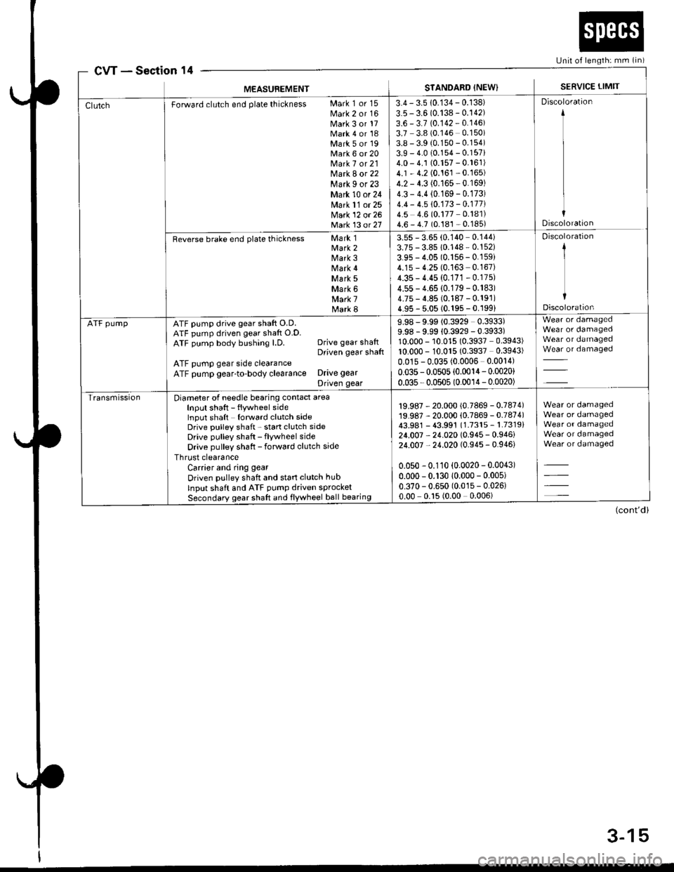
cwSection 14[Jnit of length: mm (in)
MEASUBEMENTSTANDARD {NEW}SERVICE LIMIT
Forward clutch end plate thickness Mark 1 or 15Mark 2 or 16Mark 3 or 17Mark 4 or 18Mark 5 or 19Mark 6 or 20Mark 7 or 21Mark 8 or 22Mark I or 23Mark 10 or 24Mark 11 or 25Mark 12 or 26Matk 13 ot 21
3.4 - 3.5 10.134 - 0.138)
3.5 - 3.6 (0.138 - 0.142)3.6 - 3.7 (0.142 - 0.146)3.7 3.8 (0.146 0.150)3.8 - 3.9 (0.150 - 0.154)3.9 - 4.0 (0.154 - 0.157i4.0 - 4.1 (0.157 - 0.161)4.1 - 4.2 (0.161 - 0.165)4.2 - 4.3 (0.165 - 0.169)4.3 - 4.4 (0.169 - 0.173)4.4 - 4.5 10.173 - 0.177i4.5 4.6 (0.177 0.181)4.6 - 4.7 (0.181 - 0.185)
Discoloration
Discoloration
Reverse brake end plate thickness Mark 1Mark 2Mark 3Mark 4\44 rk 5Mark 6Mark 7Mark 8
3.55 - 3.65 (0.140 0.144)3.75 - 3.85 10.148 - 0.152)
3.95 - 4.05 (0.156 - 0.159i4.15 - 4.25 (0.163 0.167)4.35 - 4.45 (0.171 - 0.175)
4.55 - 4.65 (0.179 - 0.183)4.75 - 4.85 (0.187 - 0.191)4.95 - 5.05 (0.195 - 0.199)
Discoloration
1
IDiscoloration
ATF pumpATF pump drive gear shaft O.D.ATF pump driven gear shaft O.D.ATF pump body bushing l.D. Drive gear shaftDriven gear shaft
ATF pump gear side clearanceATF pump gear-to-body clearance Drive gear
Driven gear
9.98 - 9.99 (0.3929 0.3933)9.98 - 9.99 {0.3929 - 0.3933)10.000 - 10.015 (0.3937 0.3943)10.000 - 10.015 (0.3937 0.3943)
0.01s - 0.035 (0.0006 0.0014)
0.035 - 0.0505 (0.0014- 0.0020)
0.035 - 0.0505 (0.0014 - 0.0020)
Wear or damagedWear or damagedWear or damagedWear or damaged
TransmissionDiameter of needle bearing contact areaInput shaft - flywheel sideInput shaft forward clutch sideDrive pulley shaft - start clutch sideDrive pulley shaft - flywheel side
Drive pulley shaft - forward clutch side
Thrust clearanceCarrier and ring gear
Driven pulley shaft and start clutch hub
Input shaft and ATF pump driven sprocketSecondary gear shaft and flywheel ball bearing
19.987 - 20.000 (0.7869 - 0.7874)19.987 - 20.000 (0.7869 - 0.7874)43.981 - 43.991 (1.7315 - 1.7319)24.007 - 24.020 (0.945 - 0.946)24.007 - 24.020 (0.945 - 0.946)
0.050 - 0.110 (0.0020 - 0.0043)
0.000 - 0.130 10.000 - 0.005)
0.370 - 0.650 (0.015 - 0.026)0.00 0.15 (0.00 0.006)
Wear or damagedWear or damagedWear or damagedWear or damagedWear or damaged
(cont'd)
3-15
Page 61 of 2189
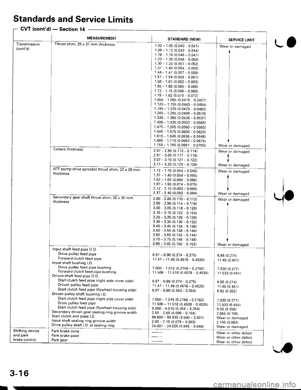
Transmission(cont'd)
MEASUREMENT
Thrust shim,25 x 31 mm thickness
STANDARD {NEW}
rlz-r-osr-o.o+o oolrr1.09 - 1.12 (0.043 0.044)1.16 1.19 (0.046 - 0.047)1.23 1.26 (0.048 0.050)1.30 - 1.33 (0.051 0.052)1.37 - 1.40 (0.054 0.055)1.44 - 1.47 (0.057 0.058)1.51 1.54 (0.059 0.061)1.58 1.61 (0.062 - 0.063)1.65 - 1.68 (0.065 0.066)1.72 1.75 {0.068 0.069)1.79 1 .a2 t0.O10 - 0.012]}1.055 1.085 (0.0415 0.0427)1.125 - 1.155 (0.0443 0.0454)1.195 - '�I.225 (0.0470 0.0482)1.265 - 1.29s (0.0498 0.0510)1.335 1.365 (0.0526 - 0.0537)1.40s - 1.435 (0.0553 - 0.0565)r.475 1.505 {0.0580 0.0593)1.545 1.575 (0.0608 0.0620)1.615 1.645 (0.0636 - 0.0648)1.685 1.71510.0663 - 0.0675)1.755 - 1.785 {0.0691 0.0703)
SERVICE LIMIT
I Wr"r - d-"-"g"d
ii
11
ir
Cotters thickness2.87 - 2.90 (0.1 13 - 0.114)2.97 - 3.00 (0.117 0.118)3.07 -3.10 \0.121 0.122)3.17 - 3.20 (0.125 0.126)
Wear,or damaged
IWear or damaoedATF pump drive sprocket thrust shim, 22 x 28 mmthickness1.12 1.1510.044 - 0.045)1.37 1.40 (0.054 - 0.055)1.62 - 1.65 (0.064 0.065)1.87 - 1.90 (0.074,0.075)2.12 2.15 (0.083 - 0.08s)2.37 2.40 (0.093 0.094)
Wear or damaged
t
{Wear or damagedSecondary gear shaft thrust shim, 25 x 35 rnmthickness2.80 - 2.85 (0.1'�t0 - 0.112)2.90 2.95 (0.114 - 0.116)3.00 3.05 (0.118 - 0.120)3.10 -3.15 10.122 0.124)3.20 - 3.25 (0.126, 0.128i3.30 - 3.35 (0.130 0.132)3.40 - 3.4s 10.134 0.136)3.50 3.55 (0.138 - 0.140)3.60,3.65 (0.142 0.144)3.70 - 3.75 (0.146 0.148)3.80 - 3.8510.150 0.152)
Wear or damaged
Wear or damaqedInput shaft feed pipe O.D.Drive pulley leed pipeForward clutch feed pipeInput shaft bushing t.D.Drive pulley feed pipe bushingForward clutch feed pipe bushingDriven shaft feed pipe O.D.Start clutch feed pipe (right side cover side)Driven pulley feed pipeStan clutch feed pipe (ftywheet housing side)Driven pulley shaft bushing LD.Stan clutch feed pipe (right side cover sroerDrive pulley feed pipeStart clutch feed pipe (flywheel housing side)Secondary driven gear sealing ring groove widthStart clutch end plate l.D.Input shaft sealing ring groove widthDnve pullev shaft LD. at sealing ring
Park brake conePark brake pawlPark gear
6.97 - 6.98 (0.274 - 0.27s)11.47 - 1'1.48 (0.4516 0.4520)
7.O0O 7.0t510.2156 - 0.2762]l11.500 11.518 (0.4528 0.4535)
6.97 - 6.9A \0.214 0.275:l11.47 - 11.48 (0.4516 _ 0.4520)8.97 8.98 10.353 - 0.354)
7.000 7.015 (0.2756 - 0.2762)1 1.500 - '11.518 (0.4528 - 0.4535)9.000 9.015 10.354 - 0.355)2.50 2.65 (0.098 0.104)88.900,88.935 (3.500 - 3.501)2.00 2.10 10.079 - 0.083)
5*
6.95 (0.274)
11.45 (0.451)
7.030 (0.277)11.533 (0.4s4)
6.95 (0.274)
11.45 (0.451)
8 95 (0.352)
t.030l0.2t7l1r.533 (0.454)
9.03 (0.356)2.655 (0. r05)Wear or damaged2.105 (0.083)Wear or damaqedShifting deviceano parKbrake control
Wear or other defectWear or other defectWear or other defect
Standardsand Service Limits
CW {cont'd)Section 14
rl
w
3-16
ro
Page 108 of 2189

Engine Removal/lnstallation
Installation (cont'd)
Engino Inst!llation:
Install the engine in the reverse order of removal.Beinstall the mount bolts/nuts in the following sequence.Failure to follow these procedures may cause excessivenois€ and vibration, and reduce bushing life.
l, Install the transmission mount and bracket, thentighten the bolts on the frame side,
NOTE; Do not tighten the bolts/nuts on the trans_mission side.
CW;
10 x 1.25 mm38 N.m {3.9 kgt m. 28 lbt.ftl
5-14
I
I
2, Install the upper bracket, then tighten the nuts inthe numbered ssquence shown (O _ @).
l'
aO t2 x 1.25 mm74 N.m 17.5 kgf.m,O t2 x t.2s mm74 N.m 17.5 kgtm,rbrft)
Page 589 of 2189

. Torque the mounting bolt and nuts in the sequence
shown.
O 12 x 1.25 mm64 N.m {6.5 kgt.m,47 lbf.fr)
@ 12 x 1.25 mm74 N.m (7.5 kgl'm,54 tbt.fr)
Check that the bushings are not twisted or offset.
Install the clip as shown.
SHIFT ROD
Turn the boot so the hole is facing down.
Make sure the boot is installed on the shift rod.
O) 12 x 'l.25 mm64 N.m 16.5 kgl.m,47 tbt.ft)
I
a
a
a
a
8 x 1.25 mmN.m t2.2 kgt.m, l6 lbl'tt)
6 x 1.0 mm9.8 N.m (1.0 kgl.m.7.2 tbf.tr)
. Apply grease to the slave cylinder push rod.
NOTE: Use only Super High Temp Urea Grease
{P/N 08798 - 9002}.
CLUTCHUNE
a
a
(P/N-6tl
08798-9002)
8 x 1.25 mm22 N.m 12.2 kgl.n.16 tbf.frl
. Turn the breather cap so that the "F" mark points at
the front of the car as shown.
Refill the transmission with the recommended oil
(see page 13-3).
Connect the positive (+) cable first, then the negative
(-) cable to the battery.
Check the clutch oDeration,
Shift the transmission and check for smooth opera-
tion.
Check the front wheel alignment (see section 18).
FRONT
13-9
Page 677 of 2189

Gearshift Mechanism
Overhaul
NOTE:
. Inspect rubber parts for wear and damage when disassembling;
. Install the spring pin and the clip on the change joint as shown'
. Turn the shift rod boot so the hole is facing down as shown'
. Make sure the shift rod boot is installed on the shift rod'
reDlace any worn or damaged Parts.
I x 1.25 mm22 N.m 12.2 kgf.m, 16 lbf.ft)
ffi-:t't:il1ii51i?"'*,
TU
/g3i'51!Exii
V ExrENsroN
EXTENSfON ilr'eol.T
EXTENSION ENDBUSHING
hV\
EXTENSIONWASI{ER B
MOUNT -_.--_-_---
@2'
--1'>=2 -:liT.i'ff"
.o,-.o*&--ffi{---*,
v/,,/ BALL SEAT
8 x 1.25 mm22 N.m 12.2 kgf'm, 16lblftl
,@
EXTENSION ROD
SHIFT ROD
SPRING
END
BOOT
N: g sHrFr LEvER
.*rr"r,o"-tf V-oiliiSi[a
MOUNTING I --::=t SHIFT I"EVERBRAcxEr / €9-l--enr xoloen
8 x 1.2s mm :-,rro""a,ii-ri- ri.z rsr.-, -.Q u
16 tbf.ft) ,,,.
,rar-aoa*,"o "u, / E ,",t.ruaa
Replace.6x1.0mm9.8 N.m ('1.0 kgt'm,7 tbr.ftt
8x22mmSPRING PINReplace.
IIt
@CLIP
9.a-"t't
PIN SHIFT ROD/
ZW
€lt#-,\
HOLE
13-97
Page 790 of 2189
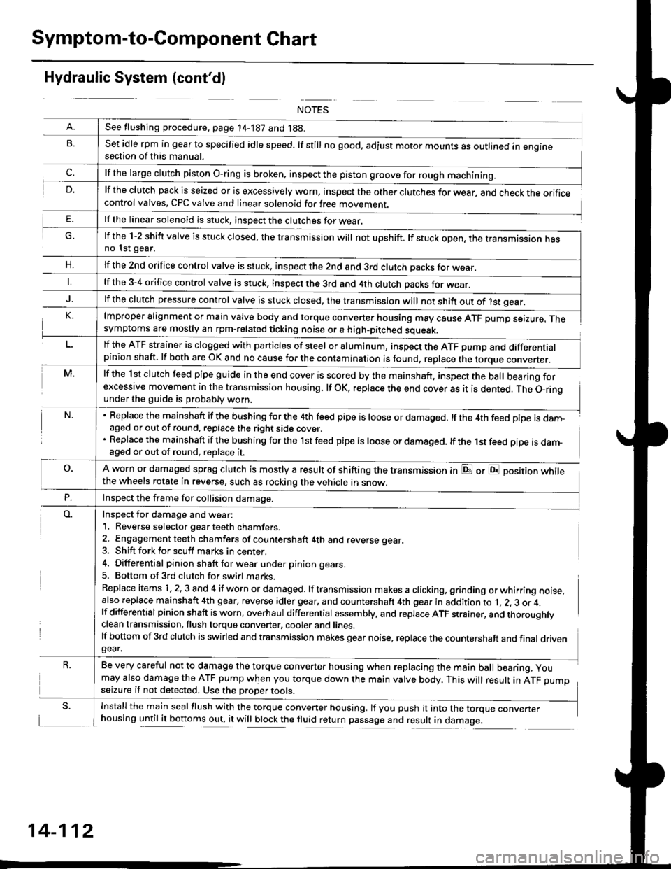
Symptom-to-Component Chart
Hydraulic System (cont'dl
G.
n,
set idle rpm in gear to specified idle speed. lf still no good, adjust motor mounts as outlined in enginesection of this manual.
lf the clutch pack is seized or is excessively worn. inspect the other clutches for wear, and check the orificecontrol valves, CPC valve and linear solenoid for free movement.
lf the linear solenoid is stuck, inspect the clutches for wear.
lmproper alignment or main valve body and torque converter housing may cause ATF pump seizure. Thesymptoms are mostly an rpm-related ticking noise or a high-pitched squeak.
lf the l st clutch feed pipe guide in the end cover is scored by the mainshaft, inspect the ball bearing forexcessive movement in the transmission housing. lf oK, replace the end cover as it is dented. The o-rinounder the guide is probably worn.
Replace the mainshaft if the bushing for the 4th feed pipe is loose or damaged. lf the 4th feed pipe is danFaged or out of round, replace the right side cover.
Replace the mainshaft if the bushing for the 1st feed pipe is loose or damaged. lf the 1st feed pipe is darn-aged or out of round, replace it.
A worn or damaged sprag clutch is mostly a result of shifting the transmission inthe wheels rotate in reverse, such as rocking the vehicle in snow.
or E position while
Inspect for damage and wear:
1. Reverse selector gear teeth chamfers.
2. Engagement teeth chamfers of countershaft 4th and reverse gear.
3. Shift fork for scuff marks in center.
4. Differential pinion shaft for wear u nder pin ion gears.
5. Bottom of 3rd clutch for swirl marks.
Replace items 1,2,3 and 4 if worn or damaged. lf transmission makes a clicking, grinding orwhirring noise,also replace mainshaft 4th gear, reverse idler gear. and countershaft 4th gear in addition to 1, 2, 3 or 4.lf differential pinion shaft is worn, overhaul differential assembly, and replace ATF strainer, and thoroughlyclean transmission, flush torque converter, cooler and lines.lf bottom of 3rd clutch is swirled and transmission makes gear noise, replace the countershaft and final drivengear.
Be very careful not to damage the torque converter housing when replacing the main ball bearing, you
may also damage the ATF pump when you torque down the main valve body. This will result in ATF pumpseizure if not detected. Use the oroper roors.
Install the main seal flush with the torque converter housing. lf you push it into the torque converterhousing until it bottoms out, it will block the fluid return passage and result in damage.
See flushing procedure, page 14-187 and 188.
lf the large clutch piston O-ring is broken, inspect the piston groove for rough machining.
lf the l-2 shift valve is stuck closed, the transmission will not upshift. lf stuck open, the transmission hasno 1st gear.
lf the znd orifice control valve is stuck. inspect the 2nd and 3rd clutch oacks for wear.
lf the 3-4 orifice control valve is stuck, inspect the 3rd and 4th clutch oacks for wear.
lf the clutch pressure control valve is stuck closed, the transmission will not shift out of 1st gear.
lf the ATF strainer is clogged with particles of steel or aluminum, inspect the ATF pump and differentialpinion shaft. lf both are OK and no cause for the contamination is found, replace the torque converter.
Inspect the frame for collision damage.
14-112
Page 869 of 2189
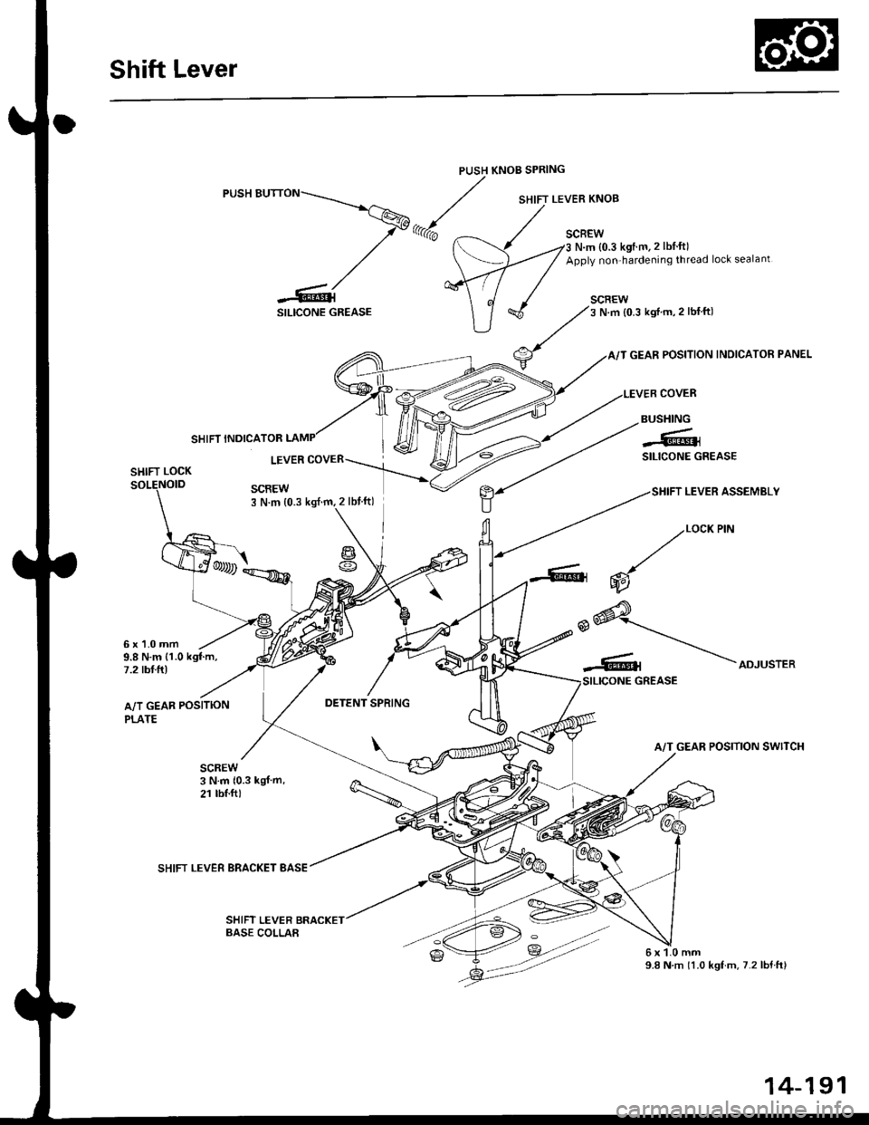
Shift Lever
PUSH KNOB SPRING
SILICONE GREASE
SCBEWN.m {0.3 kgtm.2 lbf ft)
Apply non-hardening thread lock sealant
SCREW3 N.m {0.3 kgif m,2 lblft)
GEAR POSITION INDICATOR PANEL
COVER
SHIFT LEVER ASSEMBLY
SHIFT INDICATOR
BUSHING
-61SILICONE GREASELEVERSHIFT LOCK
SCREW3 N.m {0.3
g
6x1.0mm9.8 N.m {1.0 kgf.m,7.2 tbt.ft)
A/T GEAR POSITION
PLATE
SHIFT LEVER BRACKET BASE
SHIFT LEVER
2/""*"
,.@* _.\__r.\
-Rt \ooru.r.,
A/T GEAR POSITION SWITCH
6x1.0mm9.8 N.m 11.0 kgf.m.7.2lbf.ft)
BASE COLLAA
14-191