1997 HONDA CIVIC Bushing
[x] Cancel search: BushingPage 1132 of 2189
Front Suspension
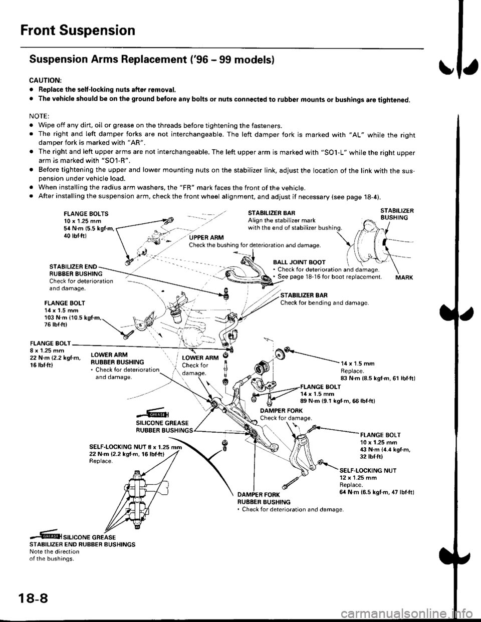
Suspension Arms Replacement ('96 - 99 models)
CAUTION:
. Replace the selt-locking nuts after removal.
. The vehicle should be on the ground betore any bolts or nuts connected to rubber mounts or bushings are tightened.
NOTE:
. Wipe off any dirt, oil or grease on the threads before tightening the fasteners.. The right and left damper forks are not interchangeable. The left damper fork is marked with "AL" while the rightdamper fork is marked with "AR'
. The right and left upper arms are not interchangeable. The left upper arm is marked with "SO1-L" while the right upperarm is marked with "SOl-R".
. Before tightening the upper and lower mounting nuts on the stabilizer link, adjust the location of the link with the sus-pension under vehicle load.
. When installing the radius arm washers, the "FR" mark faces the front ofthe vehicle.. After installing the suspension arm, ch eck the front wheel alignment, and adjust if necessary (see page 18-4).
FLANGE BOLTS10 x 1.25 mm54 N.m 15.5 kgl.m,40 tbf.ftl
STAEILIZER ENDRUBBER BUSHING
BALL JOINT BOOT. Check for deterioration and damage.. See page 18-16 for boot replacement.
STABILIZER BARCheck for bending and damage.
Check for deterioration - ---\--
and damage, -\
FLANGE BOLT14 x 1.5 mm/)l103 N.m {10.5 kg{.m,. t, ,/4,76lb{.ft) t,,"-iV
v:\FLANGE BOLT-
;iffillr-"- ilHitffi*::,"*"
and damaoe,
o.'-----------14 x 1.5 mmReplace.83 N.m {8.5 kgf.m, 61 lbf.ftl
LOWER ARMCheck for
c
JlTTda
1{ x 1.5 mm89 N.m {9.1 kgt m. 66 lbtft)
-6;SILICONE GREASERUBBER BUSHING
DAMPER FORKCheck for damage.
SELF-LOCKING NUT I x 1.2522 N.m (2.2 kg{.m, 16lbf.ftlReplace.
FLANGE BOLT10 x 1.25 mm€ N.m {4.6 kgt m.32 tbf.ft)
SELF-LOCKING NUT12x 1.25 mmReplace.6it N m {6.5 kgf.m, 47 lbf.ftl
RUEBER BUSHING. Check for deterioration and damage.
.6t",.,"o".c"KeSTAAIL|zER END RUBBER EUSHINGSNote the directionof the bushings.
18-8
Page 1133 of 2189
I
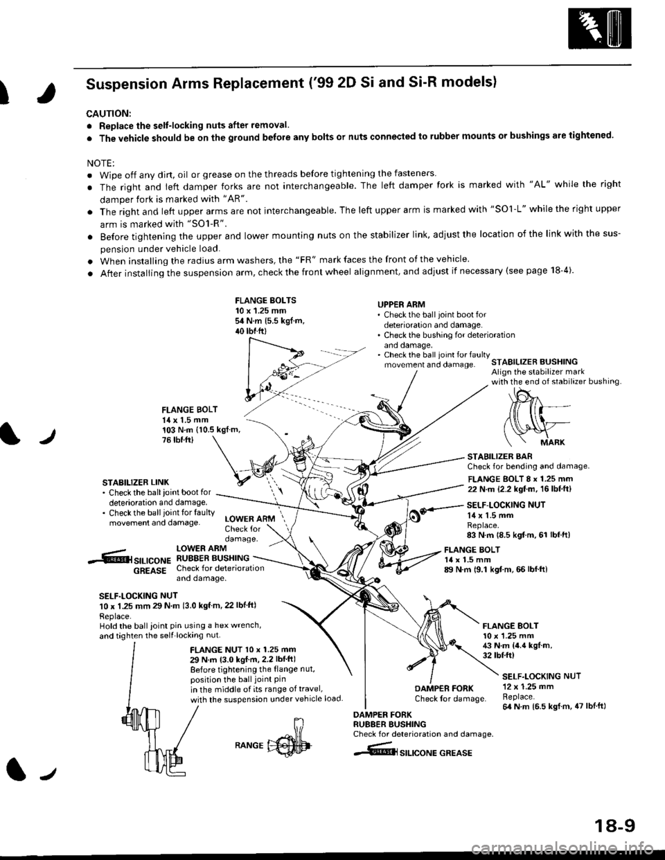
Suspension Arms Replacement ('99 2D Si and Si-R models)
CAUTION:
. Replace the selt-locking nuts after removal.
. The vehicle should be on the ground belore any bolts or nuts connected to rubber mounts or bushings are tightened.
NOTE:
. Wipe off any dirt, oil or grease on the threads before tightening the fasteners
. The right and ieft damper forks are not interchangeable. The left damper fork is marked with "AL" while the right
damper fork is marked with "AR"
. The right and left upper arms are not interchangeable. The left upper arm is marked with "SOl-L" while the right upper
arm is marked with "SO1-R".
. Before tightening the upper and lower mounting nuts on the stabilizer link, adiust the location of the link with the sus-
pension under vehicle load.
. When installing the radius arm washers, the "FR" mark faces the front of the vehicle.
. After installing the suspension arm, check the front wheel alignment, and adjust if necessary (see page 18-4).
FLANGE BOLTS10 x 1.25 mmsit N.m 15.5 kgf.m,40 tbtftl
UPPER ARM' Check the ball joint boot fordeterioration and damage.. Check the bushing for deteriorationano oamage,. Check the ball ioint fo. faultymovement and clamage.STABILIZER BUSHINGAlign the stabilizer markwith the end of stabilizer bushing
FLANGE BOLT14 x 1.5 mm
l./
103 N.m (10.5 kgf.m,76 tbr.ftl
STABILIZER LINK. Check the ballioint bootfordeterioration and damage.. Checkthe ballioint tor faultymovement and damage.
STABILIZER BARCheck for bending and damage.
FLANGE BOLT 8 x 1.25 mm22 N.m (2.2 kgf.m, 16lbf.ft)
SELF-LOCKING NUT14 x 1.5 mmReplace.83 N.m 18.5 kgf m, 61 lbf.ft)
-.6r srr-,co", hSHrtlrT.[*"u
6g619g Check for deteriorationano oamage.
SELF.LOCKING NUT10 x 1.25 mm 29 N m 13.0 kgf m, 22 lbf ftl
Replace.Hold the ball ioint pin using a hex wrench,
and taghten the self'locking nut.
LOWER ARMCheck fordamage.
FLANGE NUT l0 x 1.25 mm
29 N.m 13.0 kgI m,2.2 lbf ft)
Before tightening the {lange nut,position the ball joint Pinin the middle of its range of travel,
with the suspension under vehicle load
FLANGE BOLT14 x 1.5 mm89 N.m 19.1 kgf.m, 66 lbf.ft)
FLANGE BOLT10 x '1.25 mm43 N.m {4.4 kgf.m,32 tbtft)
DAMP€R FORKCheck lor damage.
DAMPER FORKRU88ER BUSHINGCheck for deterioration and damage.
4@lsrlrcoNE GREASE
SELF.LOCKING NUT12 x 1.25 mmReplace.64 N m 16.5 kgl.m, 47 lblft)
J
RANGE
18-9
Page 1134 of 2189
Front Suspension
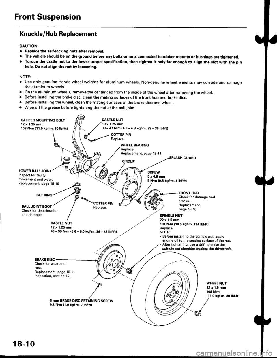
Knuckle/Hub Replacement
CAUTION:
. Replaco tho salf-locking nuts after romoval.
. The vehiclo should be on tho ground bsfore any bohs or nuls connected to rubber mounb or bushings are tightened.. Torqu€ th€ castle nut to the lowor torque specification, ihen tighton it only far enough to align th€ slot whh the pin
hole. Do not align the nut by loosening.
NOTE:
. Use only genuine Honda wheel weights for aluminum wheels. Non-genuine wheel weights may corrode and damagethe aluminum wheels.
. On the aluminum wheels, remove the center cap from the inside of the wheel after removing the wheel,. Before installing the brake disc, clean the mating surfaces of the front hub and brake disc,. Before installing the wheel, clean the mating surfaces of the brake disc and wheel.o Wipe off the grease before tightening the nut at the ball joint.
CALIPER MOUNTING BOLT12 x 1.25 mm108 N.m {11.0 kgl.m, 80lbf.ft)
LOWER BALL JOINTInspect for faultymovement and wear.
CASTLE NUT10 r 1.25 mm39 - ia7 N.m (4.0 - 4.8 kgf.m, 29 - 35 lbf,ftl
COTTER PINReplace.
WHEEL BEARINGReplace.Replacement, page 18-14
CIRCLIP
SCREW5x0.8mm5 N.m {0.5 ksl.m, 4 lbf.ftlReplacement, page 18-16
SET RING
BALL JOINT BOOT
FRONT HUBCheck for damage andcracks.Replacement,page 18-10Check for deteriorationand damage.
CASTLE NUT12 x 1.25 mm49 - 59 N.m l5.O - 6.0 kg{.m. 36 - /(} lbf,ftl
SPINDI.T ]{UT22 r 1.5 mmlEl N.m {18.5 kgf.rn, 13{ lbl.ttlReplace.NOTE:. Before instelling the spindle nut. apply6n9ine oilto th6 seating surface ofthe nut.. Atter tightening, uso a drift to stake thespindle nut should6r against the driveshaft.
BRAKE DISCCheck for wear andrust.Replacement, page 18-11lnspection, section 19.
WHEEL NUT12 x 1.5 mm'108 N.m1r1.0 kgf.m, 8lt lbf.ft)
6 mm BRAKE DISC RETAINING SCREW9.8 N.m 11.0 kgf.m, 7 lbtft)
18-10
Page 1145 of 2189
Rear Suspension
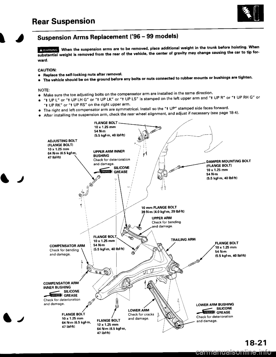
ISuspension Arms Replacement ('96 - 99 modelsl
tffi Whsn ths suspension arms ar6 to be removed. place additionsl weight in the trunk bafore hoisting' Wh€n
-substantial weight is removed ftom th6 teal of ths vehicl6, the center of gravity may change causing ths cat to tip tor'
ward.
CAUTION:
. Replace the selt-locking nuts after removal.
.Thgvehic|eshouldb€onthggroundboforeanybohsornutsconnectodtorubbelmountso]bughingsaretighton.
NOTE:
. Make sure the toe adjusting bolts on the compensator arm are installed in the same direction'
. ,,t UP 1,, or ,,t UP LH G,. or ,.t UP LK,, or "t UP LS'. is stamped on the |eft upper arm and ,,t UP R" or "t UP RH G., or
"t UP RK" or "t UP RS" on the right upper arm'
. The rightand left "ornp"n""to, uitt rre symmetrical lnstall sothe "t UP" stamped side faces forward'
.Afterinsta||ingthesuspens|onarm,checktherearwhee|alignment,andadjustifnecessary(seepagelS-4).
FLANGE BOLT10 x 1.25 mm54 N.m
ADJUSTING BOLT(FLANGE BOLTI10 x 1.25 mm
BUSHINGCheck for deteriorationand oamage.
(5.5 kgf'm, 40 lbf'ftl
UPPER ARM INNER
47 tbf.ftl
tJ
l0 mm FLANGE BOLT
N.m t4.0 kst m, 29lblftl
DAMPER MOUNTING BOLT(FLANGE BOLT}
10 x 1.25 mm
54Nm(5.5 kgd.m, iro lbf'ft)
FI.ANGE BOLT10 x 1,25 mm54 N.m(5,5 ksrf.m, 4{} lbf'ft}
UPPER ARMCheck for bendangdamage-
TRAILING ARM
COMPENSATOR ARM
Check for bendingano oamage,
COMPENSATOR ARM
INNER BUSHING
.- SILICONE.@] GREASE
Check tor deteriorataonand damage.
FLANGE BOLT10 x 1.25 mm64 N.m {6.5 kgt'm,47 lbf.ft)
LOWER ARMCheck for cracksano damage.
LOWEN ARM BUSHING
.,- SILICONE..i@l GREASECheck for deteriorationand oamage,FLANGE AOLT12 x 1.25 mm64 N.m {6.5 kgf m,47 tbf.ftt
FLANGE BOL10 x 1.25 mm
I 54 N.m
(5.5 ksrm, ao lbf'ftl
1A-21
Page 1146 of 2189
Rear Suspension
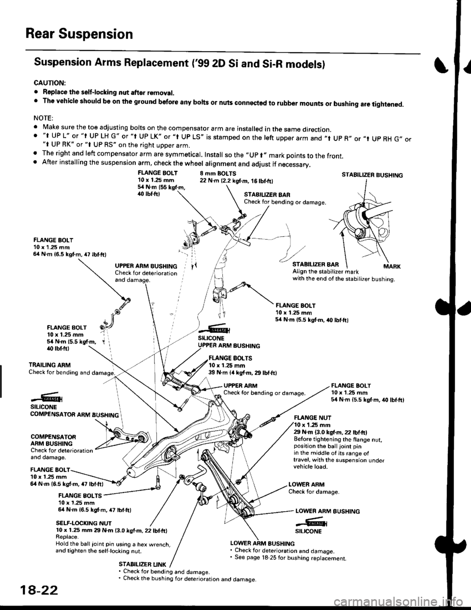
Suspension Arms Replacement ('gg 2D Si and Si-R models)
CAUTION:
. Roplace the self-locking nut after removal.' The vehicle should be on the gtound before any bohs or nuls connected to rubber mounts or bushing are tightened.
NOTE:
' Make sure the toe adjusting borts on the compensator arm are insta|ed in the same direction.. "t UP L" or "t UP LH G" or "t Up LK" or "l Up LS,, is stamped on the left upper arm and ,,t Up R,, or "t Up RH G,,"i UP RK" or "t UP RS" on the right upper arm.. The right and left compensator arm are symmeticar. Install sothe"upr"markpointstothefront.. After installing the suspension arm, check the wheel atignment and adiust if necessary,
FLANGE BOLT'10 x 1.25 mm54Nm155kgl.m,,rc lbf.ftl
8 rhm BOLTS22 N.m {2.2 kgf.m, 16 tbtfrlSTABILIZER BUSHTNG
FLANGE BOLT10 x 1.25 rnm54 N.m {5.5 kgt m, iro lbf.ft)
STAEILIZER BARCheck for bending or damage.
FLANGE BOLT10 x 1 .25 mm64 N m {5.5 kgf.m,47 lbtftl
FLANGE BOLT10 x 1.25 mm54 N.m 15.5 *gf.m,
and
UPPER ARM BUSHINGCheck for deteriorationAlign the stabitizer markwith the end ot the stabilizer bushing.
FLANGE BOLT'10 x 1.25 mm54 N.m 15.5 kgt.m, a0 lbtftl
stLrcoNEUPPER ARM BUSHINGiO lbf.ftl
TRAILING ARMCheck for bending and
EOLTS10 x 1.25 mm39 N m ll kgf.m, 29 lbf.ft)
UPPER ARMCheck for b€nding or damage.#@lstLtcoNECOMPENSATOR ARM BUSHING
COMPENSATORARM BUSHINGCheck for deteriorationand damage.
FLANGE NUTr '1.25 mm29 N.m {3.0 ksl.m,22 lbtft}Belore tightening the flange nut,position the ball joint pinin the middle ol its range oftravel, with the suspension undervehicle load.
LOWER ARMCheck for damage-
BUSHING
FLANGE BOLTl0 x 1.25 mm6l N.m 16.5 kg{.m, a7 lbt.ftl
FLANGE BOLTS10 x 1,25 mm64 N.m {6.5 kgf.m, 47 lbf.ftl
SELF.LOCKNG NUT
LOWER ARM
-GrstltcoNE10 x 1.25 mm 29 N.m (3.0 ksl.m, 22 tbtfrlReplace.Hold the ball ioinl pin using a hex w.enct.and tighten the selfjocking nut.
STABILIZEB LINK
LOWER ARM BUSHING. Check for deterioration and damaoe.' See page 18 25 for bushing replaciement.
' Check for bending and damage.. Check the bushing for deterioration ano oamage.
18-22
Page 1149 of 2189
T
11.
1)
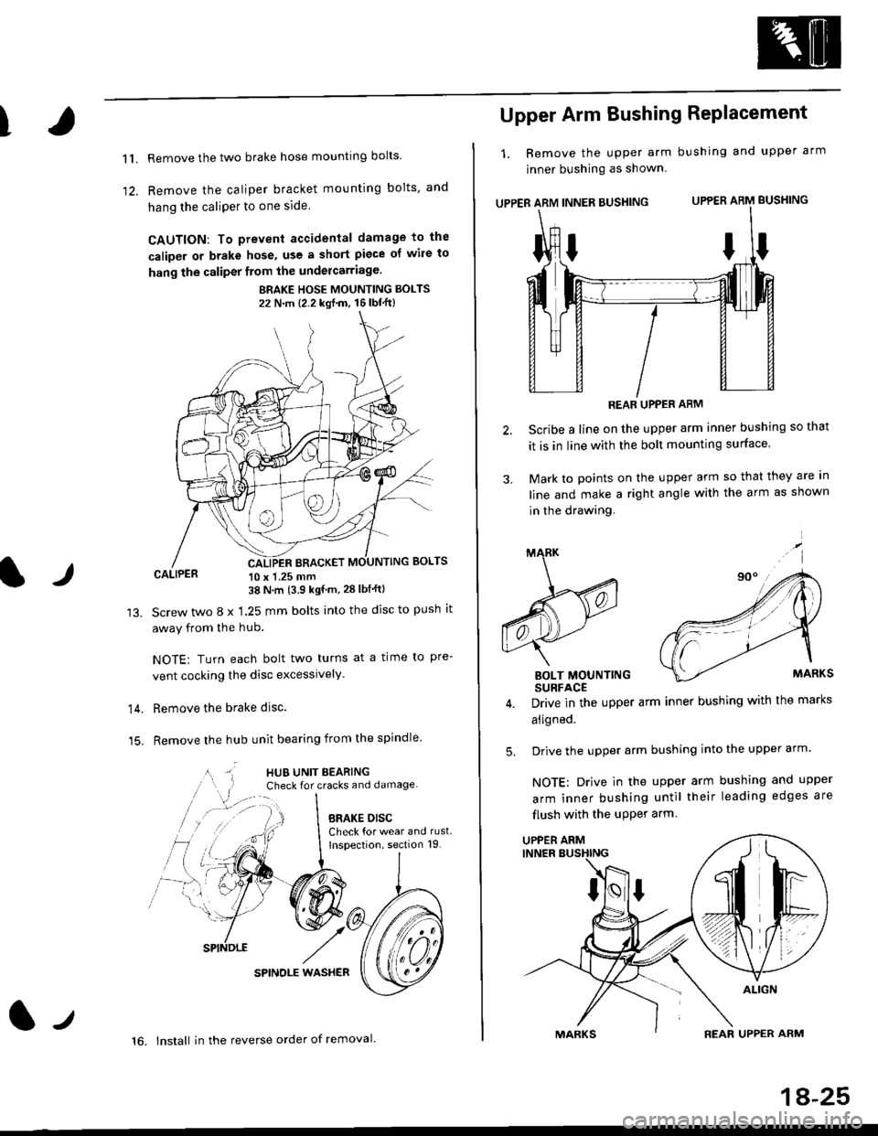
Remove the two brake hose mounting bolts
Remove the caliper b.acket mounting bolts, and
hang the caliPer to one side
CAUTION: To prevent accidental damage to the
caliper or brake hose, use a short piece of wile to
hang the caliper from the undercarriage.
BRAKE HOSE MOUNTING BOLTS
22 N'm {2.2 kgf'm, 16lbt"ft}
CALIPER 10 x 1.25 mm38 N'm (3.9 kgf'm, 28 lbf'ftl
Screw two 8 x 1.25 mm bolts into the disc to push it
away from the hub.
NOTE: Turn each bolt two turns at a time to pre-
vent cocking the disc excessively.
Remove the brake disc.
Remove the hub unit bearing from the spindle
SPINOLE WAS}IER
lr
14.
15.
lt
16. lnstall in the reverse order of removal.
1A-25
Upper Arm Bushing RePlacement
1. Remove the upper arm bushing and upper arm
jnner bushing as shown
UPPER ARM INNER BUSHING UPPER ARM BUSHING
REAR UPPER ARM
Scribe a line on the upper arm inner bushing so that
it is in line with the bolt mounting surface
Mark to points on the upper arm so that they are In
line and make a right angle with the arm as shown
in the drawing.
BOLT MOUNTINGSURFACE
Drive in the upper arm inner bushing with the marks
aligned.
Drive the upper arm bushing into the upper arm
NOTE: Drive in the upper arm bushing and upper
arm inner bushing until their leading edges are
flush with the uPPer arm
ttI
5.
UPPER ARM
Page 1235 of 2189
\:Outer Handle Replacement
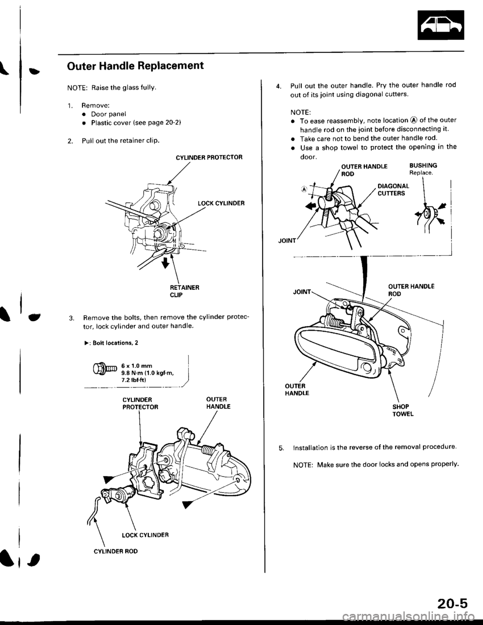
NOTE: Raise the glass fully.
'1. Remove:
. Door panel
. Plastic cover (see page 2o-21
2. Pull out the retainer cliP.
6x1.omm Ii.e N.. tr.o rgf.-, I7.2 rbr.fi) ,2
C3.
CYLINDER PROTECTOR
LOCK CYLINDEB
RETAINERCLIP
Remove the bolts, then remove the cylinder protec-
tor, lock cylinder and outer handle.
>: Bolt locaiions,2
CYLINDER
LOCK CYLINDER
CYLINDER ROD
20-5
4. Pull out the outer handle. Pry the outer handle rod
out of its joint using diagonal cutters
NOTE:
a To ease reassembly, note location @ of the outer
handle rod on the joint before disconnecting it.
. Take care not to bend the outer handle rod.
o Use a shop towel to protect the opening in the
ooor.
OUTER HANDLEROD
DIAGONALCUTTERS
SHOPTOWEL
lnstallation is the reverse of the removal procedure
NOTE: Make sure the door locks and opens properly.
BUSHINGReplace.
\
,w.
5.
i4'
Page 1241 of 2189
tOuter Handle Replacement
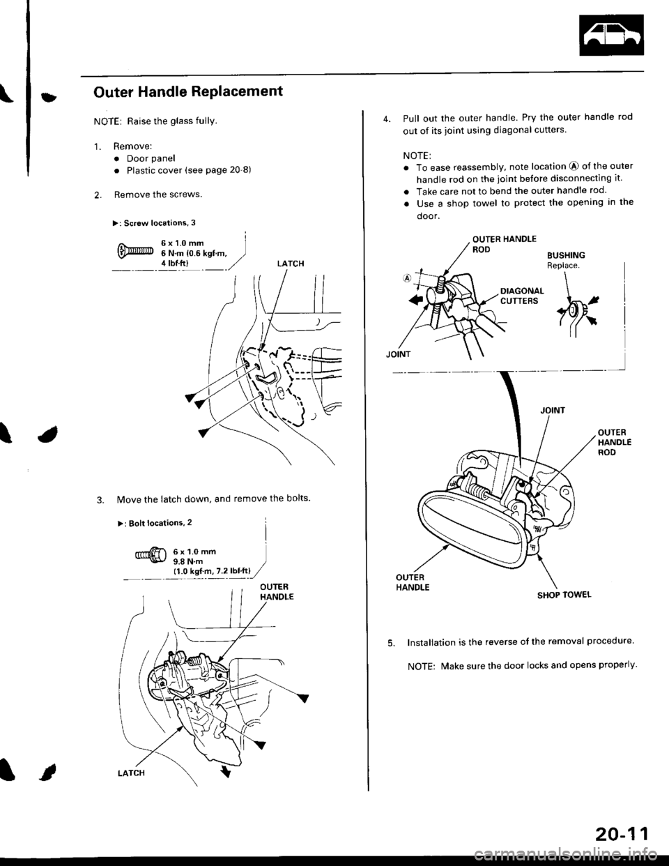
NOTE: Raise the glass fullY.
1. Remove:
. Door panel
. Plastic cover (see page 20-8)
2. Remove the screws.
>: Screw locations, 3
6x1.0mm6 N.m {0.6 kgf m,4 tbf.ftl
a\
3. Move the latch down, and remove the bolts.
>: Bolt locations,2
6x1.0mm9.8 N,m )11.O kst.n,7.2lbiftl //
4. Pull out the outer handle. Pry the outer handle rod
out of its joint using diagonal cutters.
NOTE:
. To ease reassembly, note location O of the outer
handle rod on the joint before disconnecting it.
. Take care not to bend the outer handle rod.
. Use a shop towel to protect the opening in the
door.
BUSHINGReplace.
OUTERHANDLEROD
5.
o
DIAGONAL \
:"'* ,w,
lnstallation is the reverse of the removal procedure
NOTE: N4ake sure the door locks and opens properly.
SHOP TOWEL
20-11