Page 1305 of 2189
Replacement
CAUTION: When prying with a flat-tip screwdrivet, wrap it with protective tape to prevent damage'
NOTE:
. Take care not to scratch the seat covers and body
. Remove the front seat through the door openlng'
Driver's:
NOTE: Refer to page 2O-77 for the seat belt switch harness wiring location'
SEAT CUSHION
CENTER COVER
INNER SEATTBACK
PIVOT NUT8 x 1.25 mm22 N.m l.2.216 tbf.ft)
v
l
35 tbt.ft)
10 x 1.25 mm47 N.m {4.8 kgf m,10 x 1.25 mm47 N.m {i1.8 kgl m,35 tbr.ft)
RECLINE ADJUSTER
LOW
d
ER CAP
l
RECLINE
CONNECTING WIRETo connect, twist 180'
OUTER SEATTRACK
Installation is the reverse of the removal procedure'
NOTE:
. Make sure the bushing and pivot washer
installed ProPerly.. To prevent wrinkles when installing the seat-
back cover, make sure the material is stretched
evenly over the Pad.
. Grease the sliding Portion
8 x 1.25 mm20 N.m 12.0 kgf.m,14 tbt.ft)
are
RECLINEKNOB
(cont'd)
20-75
10 x 1.25 mm47 N.m {4.8 kgf'm,35 tbtftl
Page 1306 of 2189
Front Seat
Replacement (cont'd)
Passenger's (with reclino cablel:
NOTE; Refer to page 20-77 for the recline cable location.
HEADREST
PIVOTWASHER
LOWERCAP
PIVOT NUT8 x 1.25 mm22 N.m 12,2 kgl.m,tbt.ftt
SEAT CUSHION
CENTER COVER
10 x 1,25 mm47 N.m (4.8 kgf.m,
10 x 1.25 mm47 N.m {4.8 kgf.m,3s tbt.ft)
INNER SEATTRACK
35 tbf.ftl
RECLINE ADJUSTEB
RECLINECOVER
i LowER CAP
bRECLINECABLE
x 1.25 mm47 N'm (4.7 kgf.m,35 tbtftl
SEAT
8 x 1.25 mm20 N.m {2.0 kgf.m,14 rbf.ft)
ruf, To connect, twist 180'.
lnstallation is the reverse of the removal procedure.
NOTE:
. Make sure the bushing and pivot washer are
installed properly.
. To prevent wrinkles when installing the seat-back
cover, make sure the material is stretched evenly
over the pad.
. Adjust the recline cable.
. G.ease the sliding ponion.
SEAT-BACK
20-76
Page 1310 of 2189
Rear Seat
Removal (cont'dl
3D:
>: Bolt locationsA>,6
':^2
STRIKERRemove the side t.impanel (see page 20-60).
c>,1
STBIKER
,.:) : Hook locations, 2 >: Clip locations, 14
SEAT CUSHION
STRIKER
6x1.0mm9.8 N.m (1.0 kgI.m,7.2 tbf.ft)
V
RIGHTSEAT-BACK
Pivot bolt constiuction:
TOOTHEOLOCKWASHER
BUSHING
PIVOT
Installation is the reverse of the removal procedure.
NOTE:
Ptvor BoLT BRACKETI x 1.25 mm22 N.m {2.2 kgl.m. 16 lbf.ft)Apply liquid thread lock.
. Beiore anaching the seat-back and seat cushion, make sure there are no twists or kinks in the rear seat belts andcenter belt.
. When installing the seat cushion, slip the seat belt buckles through the slits in the seat cushion.. Make sure the seat-back locks securely.
. lf necessary, adjust the striker and seat-back.
20-ao
6xr.omm I9.8 N.m (1.0 ksf.h,i
@,
EE)qr ,/
6x1omm I22 N.m {2.2 kgf.m,l,"rrr,n2
PIVOTBRACKET
LEFTSEAT.BACK
tt
A
CENTERPIVOT
\---.---
6x1.0mm
BRACKET
B>, 1
e
I
tr
-l:/*- -"HOOK
Page 1316 of 2189

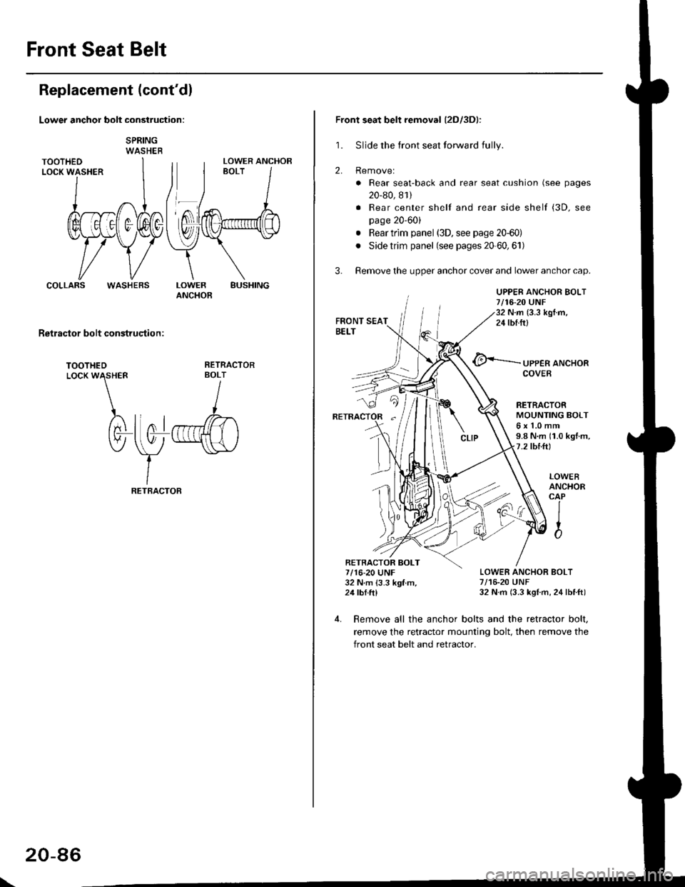
Front Seat Belt
Replacement (cont'dl
Lower anchor bolt construction:
SPRINGWASHER
COLLARSBUSHINGLOWERANCHOB
Retractor bolt construqtion :
TOOTHEDLocK W\HER
)rtnl
tv-
RETRACTORBOLT
I
llo1r",ffi)
\y
-"\s\,/
IRETBACTOF
LOWER ANCHOR
WASHEBS
\
20-86
Front seat belt removal (2Dl3Dl:
1. Sljde the front seat forward fully.
2. Removel
. Rear seat-back and rear seat cushion (see pages
20-80, 81)
. Rear center shelf and rear side shelf (3D. see
page 20'60)
. Rear trim panel (3D, see page 20-60)
. Side trim panel (see pages 20'60,61)
3. Remove the upper anchor cover and lower anchor cap.
UPPER ANCHOR BOLT7/16-20 UNF32 N.m (3.3 kgI.m,24 tbf.ftl
@<-'-.-.-.- ,PPER aNcHoR
RETRACTORMOUNTING BOLT6x1.0mm9.8 N.m (1.0 kgt m,7.2 tbtft)
LOWER ANCHOR BOLT7/16-20 UNF32 N.m (3.3 kgl m, 24lbtft)
LOWEBANCHORCAP
IIto
4. Remove all the anchor bolts and the retractor bolt,
remove the retractor mounting bolt, then remove the
front seat belt and retractor.
RETRACTOR BOLT7/16-20 UNF32 N m 13.3 kgf m,24 tbf.ftl
Page 1317 of 2189

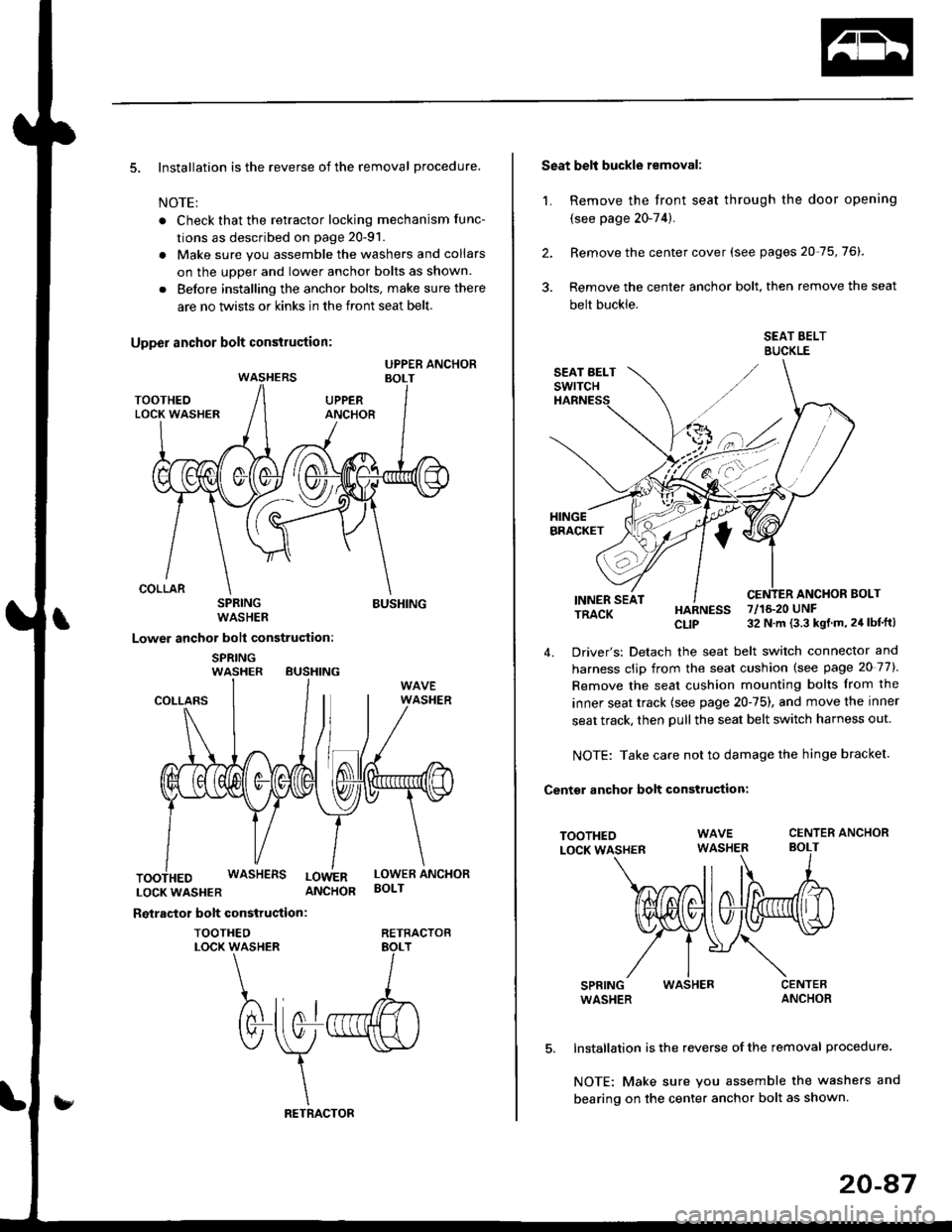
5. Installation is the reverse of the removal procedure.
NOTE:
. Check that the retractor locking mechanism func-
tions as described on page 20-91.
. Make sure you assemble the washers and collars
on the uoDer and lower anchor bolts as shown.
. Before installing the anchor bolts, make sure there
are no twists or kinks in the front seat belt.
SPRINGWASHER
Lower anchor bolt construction:
SPRINGWASHER BUSHING
BUSHING
COLLARS
LOCKWASHER ANCHOR
Reiractor bolt construction:
TOOTHEOLOCK WASHER
WASHERS LowERLOWER ANCHORBOLT
RETRACTOB
Seat belt buckle removal:
1. Remove the front seat through the door opening
{see page 20-74).
2. Remove the center cover (see pages 20-75,76).
3. Remove the center anchor bolt, then remove the seat
belt buckle.
SEAT BELTBUCKLE
ANCHOR BOLTINNER SEATTRACK
TOOTHEOLOCK WASHER
SPRINGWASHER
HARNESS 7/16.20 UNF
CLIP 32 N m (3.3 kgt m, 24 lbf'ft)
4. Driver's: Detach the seat belt switch connector and
harness clip from the seat cushion (see page 20 77).
Remove the seat cushion mounting bolts from the
inner seat track {see page 20-75), and move the inner
seat track, then pull the seat belt switch harness out.
NOTE: Take care not to damage the hinge bracket.
Centsr anchor bolt construction:
CENTER ANCHORBOLT
WASHER
Installation is the reverse of the removal procedure.
NOTE: Make sure you assemble the washers and
bearing on the center anchor bolt as shown.
20-47
Page 1356 of 2189
,-. ): Hook locations^(:).zB() ' t2D:
>: Bolt locationsA>,6c>,1B>. 1
6le
9rJ*'Ll-",-, i VH 16 rbr'frl ) g
,/v
6x1.omm i9.8 N.m 11.0 ksf.m,l7.2 rbf.ft) i
>: Clio locations, 14
PIVOT BRACKET
V
CENTER
RIGHT SEAT-BACK
LEFTSEAT-BACK
SEAT CUSHION
lnstallation is the reverse of the removal procedure.
NOTE:
. Before attaching the seat-back and seat cushion, make sure there are
center belt.
. When installing the seat cushion, slip the seat belt buckles through the
. Make sure the seat-back locks securely
. lf necessary, adjust the seat-back latch and seat-back
BUSHING
PIVOT BOLTBRACKET8 x 1.25 mm22 N.m {2.2 kgf.m, 16 lbIft)Apply liquid thread lock.
no twists or kinks in the rear seat belts and
slits in the seat cushion.
SEAT-AACK MAT
VV
TOOIHEDLOCKWASHER
PIVOT BRACKET
20-127
Page 1362 of 2189
4. Note the position of the ioint on the handle rod (A)'
Prv the handle rod ol the joint using diagonal cut-
ters; take care not to bend the rod Remove the
hatch handle.
BUSHINGReplace.
lnstall in the reverse order of removal, and note
these items:
Make sure
the handle rod is connected properly
Before installing the hatch trim panel, make sure
the hatch opens ProPerlY.
@
Hatch Latch/Lock CYlinder
Replacement
1.
2.
Remove the hatch trim panel (see page 20-63)'
Remove the hatch latch screws
>: Screw locations,3
6x1,0mm9.8 N.m 11.0 kgf'm,
7.2 tbt f0
HATCHLATCH
Disconnect the lock rod, the handle rod, the lock
cylinder rod. and the connector, then remove the
hatch latch.
LOCK CYLINDERROD
''---tCONNECTOR
HANDLEROD
(cont'd)
20-133
Page 1368 of 2189
Reassemble in the reverse order of disassembly' and
note these items:
. Make sure the bushing and pivot washer are installed
properly.
. To connect the connecting wire, twist it 90'.
. Replace the back cover clips with new ones
. To prevent wrinkles when installing the seat-back
cover, make sure the material is stretched evenly
over the pad.
. Apply multipurpose grease to the moving portion of
the seat track.
Front Seat Torsion Bar
Replacement
NOTE| Take care not to tear the seams or damage the
seat covers.
1. Remove the seat cushlon
2. Remove the torsion bar from the hook with a flat tip
screwdriver, then pull out the torsion bar from the
seat cushion frame Put on gloves to protect your
ha nds.
TORSIONSAR
SEAT CUSHION FNAME
TORSION BARSEAT CUSHION
FLAT TIP SCREWDRIVER
3. lnstall in the reverse order of removal'
20-139