1997 HONDA CIVIC valvo
[x] Cancel search: valvoPage 114 of 2189

VTEC Control System
Troubleshooting Flowchart
tFtrsrl #ilH:::lj1t:"J:T,?ffnostic
rrouble code (Drc) Pr25e: A probrem in the vrEc Pressure switch circuit or
Reter to page 1 l-38 th roug h 1 1-55 before trou bleshooting.
* Road Test:Accelerate in 1st gear to an engine speed over 3,000 rpm(D16Y5 engine) or 6,000 rpm (D'16Y8 engine).Hold that engine speed for at least two seconds.It DTC P1259 is not repeated during the first road test, repeatthis test two more tames.
VTEC PRESSURE SWITCH 2PCONNECTOR
Terminal side ofmale terminals
Wire sid6 ol femalerermtnats
VTM
l1 (BLu/BLK)
f;-) |I
I
Y
I
The MIL has been reoorted on.DTC P1259 is sto.ed.
Check the VTEC Cont.ol Syst6m:1. Do the engine control module(ECM)/powertrain control module lPCM) Reset Procedure (see
section 11).2. Stan the engine.3. Warm up the engine to normaloperating temperature (cool-
ing fan comes on).4. Do the Boad Test.*Intermittont tailura, 3y3t.m is OKat thia time.Check for ooor connoctionr o.loose wirea at VTEC oiassurclwitch, VTEC solonoid valvo .ndECM/PCM,
ls OTC P1259 indicated?
Test rhe VTEC Prensure Switch:1. Turn the ignition switch OFF.2. Disconnect the VTEC Pressureswitch 2P connector.3. Check for continuity betweenVTEC pressure switch 2P con-nector terminal No. 1 and No.2.
Replace the VTEC preasure 3witch.ls there continuity?
Te3t the VTEC Pressure SwitchWire:1. Turn the ignition switch ON lll).2. Measure the voltage betweenVTEC press u re switch 2Pconnector No. l and bodyground.
In3poct for en opon or shod toground in thG wi.. bctwoon thoVTEC pro$ur6 switch rnd ECM/PCM l'96 - 9a: C15,'99 - 00: C101.lf tha wiro i3 OK,3ubrtitute aknown-good ECM/PCM andrecheck.
ls there battery voltage?
{To page 6'4i
Page 150 of 2189

Valve Guides
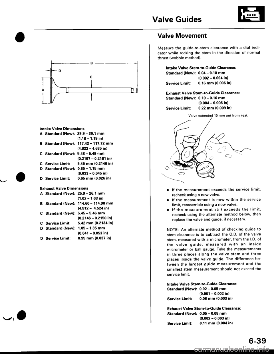
lntake Valve Dimensions
A Standsrd lNewl: 29.9 - 30.1 mm
B Standard (New):
C Standald {Newl:
C Service Limit:
D Standard (New):
D Service Limit:
11.18 - 1.19 inl
117.42 - 117.72 mm
(4.523 - 4.635 inl
5.'18 - 5.49 mm
{0.2r57 - 0.2r61 in)
5.,[5 mm (0.21,16 in]
0.85 - 1.15 mm
(0.033 - 0.0'15 in)
0.65 mm (0.026 in)
Exhaust Valve Dimensions
A Standard lNew): 25.9 - 26.1 mm
B Standard {Newl:
C Standard {New):
C Service Limit:
D Standard {New):
D Service Limit:
(1.02 - 1.03 in)
114.60 - 114.90 mm
11.512 - 4.521in1
5.i[5 - 5.46 mm
10.21lt6 - 0.2150 inl
5.,12 mm 10.213'l in)
1.05 - 1.35 mm
{0.041 - 0.053 in)
0.95 mm {0.037 in}
Valve Movement
Measure the guide-to-stem clearance with a dial indi-
cator while rocking the stem in the direction of normal
thrust (wobble method).
lniake Valve Stem-to-Guide Clearance:
St8ndard lNew): 0.04 - 0.10 mm
10.002 - 0.004 in)
Service Limit: 0.16 mm 10.006 in)
Exhaust Valvs Stem-to-Guide Glearance:
Standard {New}: 0.10 - 0.16 mm
10.004 - 0.006 in)
Sorvice Limit 0.22 mm (0.009 in)
O/'-_)
. lf the measurement exceeds the service limit,
recheck using a new valve.
. lf the measurement is now within the service
limit, reassemble using a new valve.
. lf the measurement still exceeds the limit,
recheck using the alternate method below, then
replace the valve and guide, if necessary.
NOTE: An alternate method of checking guide to
stem clearance is to subtract the O.D. of the valve
stem, measured with a micrometer, from the l.D. of
the valve guide, measured with an inside
micrometer or ball gauge. Take the measurements
in three places along the valve stem and three
places inside the valve guide. The difference be-
tween the largest guide measurement and the
smallest stem measurement should not exceed the
service limit.
lntake Valve Stgm-to-Guidg clearance:
Standard {Newl: 0.02 - 0.05 mm
{0.001 - 0.002 in)
Ssrvico Limit 0.08 mm (0.003 in)
Exhaust Valvo Stem-to-Guide Clearance:
Standard {New): 0.05 - 0.OB mm
{0.002 - 0.003 in)
S€rvice Limit 0.11 mm (o'Ooil in)
Valve extended 10 mm out from seat.
6-39
Page 161 of 2189

VTEC Control SYstem
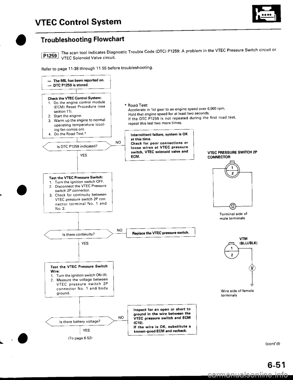
The scan tool indicates Diagnostic Trouble Code {DTC) Pl259:
VTEC Solenoid Valve circuit
Refer to page 1'l-38 through 11 55 before troubleshooting
Troubleshooting Flowchart
YES
A problem in the WEC Pressure Switch circuit or
* Road Test:Accelerate in 1st gear to an engine speed over 6,000 rp '
Hold that engine speed for at leasttwo seconos'
lf the DTC P1259 is not repeated during the first road test'
repeat this test two more times
VTEC PRESSURE SWITCH 2P
CONNECTOR
Terminalside ofmale termtnals
WM
/1 IBLU/BLKI
/ 1 Y------rt--------- l I
\1-/ |I
I
I1
Wire side of femaleterminals
(cont'd)
6-51
The MIL has been teported on.
DTC P1259 is siored.
Check the VTEC Control SYsiem:
1. Do the engine control module(ECM ) Reset Procedure (see
section 11).
2. Start the engine
3. Warm uP the engine to normal
operating temPerature (cool
ing fan comes on).
4. Do the Road Test.*lntermittent failure, sYstem is OK
at this time.Check for Poor connectlons or
loose wires at VTEC Pressureswilch. VTEC aolenoid valvo and
ECM.
ls DTC P1259 indicated?
Test the VTEC Pressure Switch:
1. Turn the ignition switch OFF.
2. Disconnect the VTEC Pressure
switch 2P connector.
3. Check for continuity between
VTEC pressure switch 2P con
nector telminal No 1 and
No.2.
Reolace the VTEC Pre3sure switch.
Test the VTEC Pressure Switch
Wire:1. Turn the ignition switch ON (ll).
2. N4easure the voltage between
VTEC press u re switch 2P
connector No. 1 and bodyground,
Inspect lor an open or short toground in the wire between the
VTEC orassure swilch and ECM
{c101.lf the wire i3 OK, substitute a
known-good ECM and recheck.
{To page 6 52)
Page 187 of 2189

Valves, Valve Springs and Valve Seals
Removal
NOTE: ldentify valves and valve springs as they are
removed so that each item can be reinstalled in its origi-
nal Dosition.
l. Using an appropriate-sized socket and plastic mal-
let, lightly tap the valve retainer to loosen the valve
keeoers.
PLASTIC
Install the valve spring compressor. Compress the
spring and remove the vSlve keepers.
VALVE SPRINGCOMPRESSORATTACHMENT07757 - PJ1010A
VALVE SPRINGCOMPRESSOR ATTACHMENTEXTENSIONOTMAF - PRgOIOA
I
Sn.p-on CFr1lCOMPRESSOR
6-77
3. Installthe valve guide seal remover.
VALVE GUIDE SEAL REMOVERCOMMERCIALLY AVAILABLELtst-E P/N 571100 ()R KD3350
4. Remove the valve guide seal.
Valve Dimensions
lntake Valvo
A Standsrd {Newl; 32.90 - 33.10 mm (1.295 - 1.303 in}
B St ndard {New}: 101.00 - 101.30 mm (3.976 - 3'988 in}
C Stsndard (Nowl: 5./t5 - 5.,185 mm (0.2156 - 0.2159 in)
C Servico Limit 5.445 {0.21/l| in)
D Siandard (N!w): 1.05 - 1.35 mm (0.041 - O.05il inl
D S€.vice Limit: 0.85 mm {0.033 inl
Exhaust Valve
A Standard lNewli 27.90 - 28.10 mm (1.098 - 1.106 in)
B Stlndard {Nowl: 100.m - 1qr,90 mm {3.961 - 3.972 in)
C Stsndard {Now}: 5.450 - 5.,[60 mm {0.21,16 - 0.2150 in)
C Service Limit 5.420 10.213,0 inl
D Standard {New): 1.65 - 1.95 mm (0.065 - 0.077 in)
D Sorvico Limit: l.ils mm 10.057 inl
Page 470 of 2189

I
I
L
IACV N(oRN)*IACV P{BLK/BLU'
ECM/PCMCONNECTON B (25PI
IACV N(oRNt.
Wire side of female terminals
IAC VALVE 3P CONNECTOR
IACV NIACV P
IACV P
IBLK/BLUI
IGP
Terminal side of male
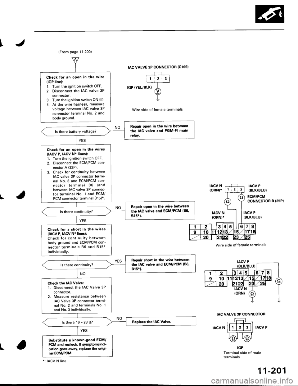
(From page 11 200)
IAC VALVE 3P CONNECTOR {C1O9I
IGP (YEL/BLK)
Wire side of female terminals
Check toi an open in thg wire
{lGP line):1. Turn the ignition switch OFF.
2. Disconnect the IAC valve 3P
connector.3. Turn the ignition switch ON (ll)
4, At the wire harness, measure
voltage between IAC valve 3P
connector terminal No. 2 and
body gro!nd.
Repair open in the wire between
the IAC valve and PGM-FI main
reraY.
Check for an open in the wires
IIACV P. IACV N' lines):
1. Turn the ignition switch OFF.
2. Disconnect the ECM/PCM con-
nector A (32P).
3. Check lor continuity between
IAC valve 3P connector termi'nal No. 3 and ECM/PCM con-necto r terminal B6 (and
beNveen IAC valve 3P connector terminal No. 1 and ECM/PCM connector terminal 815)*.
Repair open in the wiro ltstwcen
the IAC valvo and €CM/PCM (86,
815'1.
Check for a shon in the wires(IACV P, lACv N* linesl:Check for continuity between
body ground and ECM/PCM con-
nector terminals 86 and 815*
individually.
Reoair short in the wiro Mweonthe lac valve end ECM/FCM (86,
815*).ls there continuity?
Check the IAC valv€:l. Disconnect the IAC Valve 3P
connector,2. Measure resislance betweenIAC Valve 3P connector termi
nal No. 2 and terminals No 1and No.3 individually
ls there 16 - 28 O?
Substituta . known-good ECM/
PCM and rochcdc f 3ymptom/indication go€a away, r€dace the original ECM/Pqvl.
"r IACV N line
N
11-201
Page 524 of 2189

4
The scan tool indicates Dlagnostic Trouble cod€ {DTc} Po4ol: lnsufficient flow in the Exhaust Gas Recirculation
(EGR) svstem.
Doscription
Deterioration (clogging, leakage, etc.) in the EGR line or EGR valve is detected by means of the changes in MAP before
and after the operation of the EGR valve.
lf deterioration has been detected during two cons€cutive driving cycles, the MIL will come on and DTC P0401 will be
stored.
Po$ible Causeg
. Clogging. leakage in the EGR line
. Faulty EGR valve
Troubleshooting Flowchart
\
- Tho MIL ht! bacn rgportod on.- DTC m40l is 3torod.
Problom vorification:
1. Do the ECM/PCM Reset Proce-
dure.2. Connect the SCS service con-
nector,3. Tost-drive under the following
conditions.- Without any electrical load- Decelerate lrom 55 mPh(88 km/h)lor at least 5 sec-
onos
lntormiftam f!ilu.a, ayltam ia OK
.t thb time,
- Clo.n tho inttkc mlnifold EGRport wittr carbursto. clotner.- Cl.an the pa$lgo insido tho
EGR valvo with crrburator
cloanol or aoglaca tha vllvo.
Page 529 of 2189

Emission Control System
Exhaust Gas Recirculation (EGR) System (Dl6Y5 engine with CW) (cont'dl
tJ
(From page 11-259)EGR CONTROL SOLENOIDVALVE 2P CONNECTOR {C142}
Wire sideof lemaleterminals
ECMCONNECTORa t32Pl
Chock lor an open in the wire (E
SOL linsl:1. Turn the ignition switch OFF.2. Disconnect the 2P connectorIrom the EGR control solenoid
3. Disconnect the ECN4/PCM con-nector A (32P) (B (25P))* fromthe EcM/PCM.4. Check tor continuity betweenECM/PCl, connector terminal47 (86)* and the EGR controlsolenoid valve 2P connectorterminal No.2.
Repair opon in th. wir. bstwocntha EGR control 3ol€noid valvoand tho ECM/PCM (A7 186l'1.
ls there continuity?
Check for . rhort in the wire(ESOL linel:Check for continuity between theEGR controlsolenoid valve 2P con-nector terminal No. 2 and bodyground,
R.p.ir ahort in tha wi.c b.twecnthe EGR control iolonoid vllyeand th. ECM/FCM {A7 (46}rl.
Check for an opon in the wiroIGND linel:Check for continuity between theEGR controlsolenoid vaive 2P con-nector terminal No. I and bodyground,
Rcpai. op€n in the wir6 b6'twoenthe EGR control rol.noid valveand G101.
Sub3titule a known-good ECM/PCM and rechock. lf symptom/indication goes away, replac€the original ECM/PCM.
ESOL
IRED)
ESOLIRED)
Wire sideof femaleterminals--_-]
I
EGR CONTROL SOLENOIDVALVE 2P CONNECTOR ICl'2}
Wire sideof femaleilterminals
ECMCONNECTORB l25P)ESOL(REDI
Wire sideof femalerermtnats
*: '99 - 00 models
11-260
Page 532 of 2189

T
t
lFrom page 11-262)
Chock for rn opon in the wire
{EGR L linel:1. Reconnect the EGR valve connector.2. Tu.n the ignition switch ON (ll).
3. Measure voltage betweon thePCM connector terminals Dgand Dl1.
Check tor th€ wirc (EGR L line):
Check for continuity betweenECM connector terminal Dg andbody ground.
ls there approx. 1.2 V?
Roprir op6n in the wirs botweanthe EGR valvo.nd th. ECM lD9).
Rooair ahort in tho wiro baftr,otn
tho EGR v.lv..nd the ECM lDgl.
Ch€ck the EGR valve:1. Turn the ignition switch OFF.2. Disconnect the EGR valve 6P
connector.3. Connect the battery positive
terminal to EGR valve 6P con-nectorterminal No. 6.4. Stan the engine and let it id'e,then connect the battery nega_
tive terminal to EGR valve 6Pcon nector term inal No, 4,
ECM CONNECTOR D I16P'
Wire side oI female terminals
EGR VALVE 6P CONNECTOR
wire sid6 of lemale te.minals
(cont'd)