1997 HONDA CIVIC Diffe
[x] Cancel search: DiffePage 643 of 2189

Mainshaft, Countershaft, Shift Fork
Removal
1.Remove the mainshaft and the countershaft assem-
blies with the shift forks from the clutch housing.
NOTE: Tape the mainshaft spline before removing
the mainshaft and the countershaft assemblies.
Remove the spring washer and the washer'
v
MAINSHAFT
COUNTERSHAFT
Remove the differential assembly from the clutch
housing.
Tape the
splrnes.
WASHER
DIFF€RENTIAL ASSEMBLY
4. Remove the chamber Plate.
CLUTCH HOUSING
CHAMEEF PLATE
CLUTCH HOUSING
13-63
Page 662 of 2189

Differential
Index
FINAL DRIVEN GEARInspect tor wear and damage.
80 mm SHIMSelection, page'13,84
101 N.m {10.3 kgtm,74.5 lbf.ft)Left-hand threadsBALL BEAFINGInspect foa wear and ooeration.
13-82
Backlash Inspection
1. Place the differential assembly on V-blocks and installboth axles.
Measure the backlash of both pinion gears. lf thebacklash is not within the standard, replace the dif,ferential carrier.
Standard (New): 0.05 - 0.15 mm (0.002 - 0.006 inl
DIAL INDICATOR
Page 664 of 2189

Differential
Thrust Shim Adjustment
1. Install the differential assembly, making sure it bot
toms in the clutch housing, using the special tool as
shown.
ORIVER, 40 mm LO.o7746-0030100
lnstall the 80 mm shim.
NOTE: lnstall the 80 mm shim that was removed.
mm SHIM
13-84
(
4.
Install the transmission housing (see page 13-94).
NOTE: Do not apply liquid gasket to the mating sur-
face of the clutch housing.
Tighten the transmission housing attaching bolts(see page 13-94).
I x 1.25 mm
27 N'm (2.8 kgf.m, 20 lbf.ftl
Use the special tool to bottom the differential assem.
bly in the clutch housing.
Measure clearance between the 80 mm shim and
bearing outer race in the transmission housing.
Page 694 of 2189

Description
Electronic Control System {cont'dl
Ascending Control
When the PCM determines that the vehicle is climbing a hill in E position, the system oxtends the sngagement area of2nd gear and 3rd gear to prevent ths transmission from fr€quently shifting between 2nd and 3rd gears, and between 3rdand 4th gears, so the vehicle can run smooth and have more power when needed. There are two ascending modes withdifferent 3rd gear driving areas according to the magnitude of a gradient stored in the pCM.
NOTE:
. The PCM memory contains shift schedules between 2nd and 3rd gears, and between 3rd and 4th gears that enable thePCM's fuzzy logic to automatically select the most suitable gear according to the magnitude of a gradient. Fuzzy logic is a form of artificial intelligence that lets computers respond to changing conditions much like a humanmind would,
Dssconding Control
When the PCM determines that the vehicle is going down a hilt in E position, the shift-up speed from 3rd to 4th gearwhen th€ throftle is closed becomes faster than the set speed for flat road driving to widen the 3rd gear driving area.This, in combination with engine braking from the deceleration lock-up, achieves smooth driving when the vehicle isdescending. There are two descending modes with different downshift (4 - 3) schedules according to the magnitude of agradient stored in the PCM. When the vehicle is in 4th gear, and you are decelerating on a gradual hill, or when you areapplying the brakes on a steep hill, the transmission will downshift to 3rd gear. When you accel6rate, the transmission willthen return to 4th gear.
ASCENDING MODEDESCENDING MODE
4TH SHIFTING
L.
F
CHARACTERISIICSCONTROL AREA
ff.1"11", vehicr. 3pe€dff;Tlr., vohicre speed
GRADUAL ASCENOINGCONTROL AREA
Docel6ration Control
When the vehicle goes around a corner. and needs to first decelerate and then accelerate. the rcM sets the data for decelerationcontrol to reduce the number of times the transmission shifts. When the vehicle is decelerating from speeds above 26 mph(41 km/h), the rcM shifts the transmission from 4th to 2nd earlier than normal to cope with upcoming acceleration.
14-16
Page 773 of 2189

Troubleshooting Flowchart - Mainshaft Speed Sensor
NOTE: Record all freeze data before you troubleshoot.
Possible Causg
. Diaconn€cted mainshaft spoed
sen3or connector'Short or open in mainshaft
sDeed sen3or wile. Faulty main3halt speed sensor
NOTE: Code P0715 (15) on the PCM doesn't
always mean there's an electrrcal problem in
the mainshaft or countershaft speed sensor
circuit; code P0715 {15) may also indicate a
mechanical problem in the transmissjon Any
problem causing irregular countershaft to
mainshalt speed difference can cause thls
code.
lll ,..TT
(ol-i-l
tl
side oI male terminals
MAINSI{AFT SPEEDSENSOR CONNECTOR
Terminal
PCM CONNECTOR D (16P)
NMSG (WHT)
Wire side of female terminals
(cont'd)
14-95
. OBD ll Scan Tool indicates Codem715.. Sell-diagno3is E indicator indi-
cates Code 15.
Check the mainshaft and counter-
shatt speed sensors installation,
and check them for damage.
Are the mainshaft and countershaft
speed sensor installed properly,
and not damaged?
Rsinalall or replace and rocheck.
Mea3u.e Meinshalt SPeod
Sensor Residance al the Sen3or
Connector:1. Disconnect the 2P connectorfrom the mainshaft sPeedsensor.2, Nreasure mainshaft speed sen_sor resistance at the sensorconnector.
ls the resistance 400 - 600 O?
Check Mainshaft Sp.ed Sen3o.
for a Short Circult:1. Disconnect the D (16P) con-nector trom the PCM.2. Check lor continuity betweenbody ground and the D11 ter'minal and D12 terminal indi
vidually.
Bopair 3hort in the wiros b€twe€nthe 011 and D12 termin.ls rndth€ main3hett sp€€d aensoa.ls there continuity?
To page 14 96
Page 790 of 2189

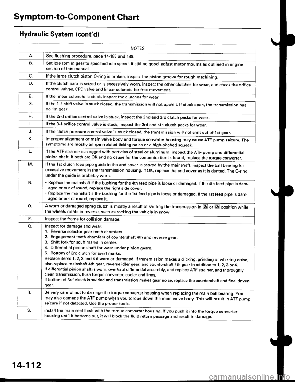
Symptom-to-Component Chart
Hydraulic System (cont'dl
G.
n,
set idle rpm in gear to specified idle speed. lf still no good, adjust motor mounts as outlined in enginesection of this manual.
lf the clutch pack is seized or is excessively worn. inspect the other clutches for wear, and check the orificecontrol valves, CPC valve and linear solenoid for free movement.
lf the linear solenoid is stuck, inspect the clutches for wear.
lmproper alignment or main valve body and torque converter housing may cause ATF pump seizure. Thesymptoms are mostly an rpm-related ticking noise or a high-pitched squeak.
lf the l st clutch feed pipe guide in the end cover is scored by the mainshaft, inspect the ball bearing forexcessive movement in the transmission housing. lf oK, replace the end cover as it is dented. The o-rinounder the guide is probably worn.
Replace the mainshaft if the bushing for the 4th feed pipe is loose or damaged. lf the 4th feed pipe is danFaged or out of round, replace the right side cover.
Replace the mainshaft if the bushing for the 1st feed pipe is loose or damaged. lf the 1st feed pipe is darn-aged or out of round, replace it.
A worn or damaged sprag clutch is mostly a result of shifting the transmission inthe wheels rotate in reverse, such as rocking the vehicle in snow.
or E position while
Inspect for damage and wear:
1. Reverse selector gear teeth chamfers.
2. Engagement teeth chamfers of countershaft 4th and reverse gear.
3. Shift fork for scuff marks in center.
4. Differential pinion shaft for wear u nder pin ion gears.
5. Bottom of 3rd clutch for swirl marks.
Replace items 1,2,3 and 4 if worn or damaged. lf transmission makes a clicking, grinding orwhirring noise,also replace mainshaft 4th gear, reverse idler gear. and countershaft 4th gear in addition to 1, 2, 3 or 4.lf differential pinion shaft is worn, overhaul differential assembly, and replace ATF strainer, and thoroughlyclean transmission, flush torque converter, cooler and lines.lf bottom of 3rd clutch is swirled and transmission makes gear noise, replace the countershaft and final drivengear.
Be very careful not to damage the torque converter housing when replacing the main ball bearing, you
may also damage the ATF pump when you torque down the main valve body. This will result in ATF pumpseizure if not detected. Use the oroper roors.
Install the main seal flush with the torque converter housing. lf you push it into the torque converterhousing until it bottoms out, it will block the fluid return passage and result in damage.
See flushing procedure, page 14-187 and 188.
lf the large clutch piston O-ring is broken, inspect the piston groove for rough machining.
lf the l-2 shift valve is stuck closed, the transmission will not upshift. lf stuck open, the transmission hasno 1st gear.
lf the znd orifice control valve is stuck. inspect the 2nd and 3rd clutch oacks for wear.
lf the 3-4 orifice control valve is stuck, inspect the 3rd and 4th clutch oacks for wear.
lf the clutch pressure control valve is stuck closed, the transmission will not shift out of 1st gear.
lf the ATF strainer is clogged with particles of steel or aluminum, inspect the ATF pump and differentialpinion shaft. lf both are OK and no cause for the contamination is found, replace the torque converter.
Inspect the frame for collision damage.
14-112
Page 802 of 2189

Transmission
Removal(cont'd)
'10. Remove the cotter pins and castle nuts, th€n separatethe balljoints from the lower arms (see section 1gl.
DAMPER PINCH BOLT
NUT
FORI(FORK BOLT
11. Remove the right damper fork bolt. th€nright damper fork and dampor.
COTTER PINReplace.
separate
12.
1a
14.
Pry the right and left driveshafts out ofthe differential.
Pull on the inboard joint to remove the right and leftdrivsshafts (see section 16).
Tie plastic bags over the driveshaft onds.
NOTE: Coat all precision finished surfaces with cleanengine oil.
Remove the exhaust pipe A,
NOTE: Dl6YB engine is shown; D16y7 engine issimilar.
t9.
SELF-LOCKING NUTReplace.
L
14-124
EXHAUST PIPE AMOUNT/BRACKET
17.
18.
16. Remove the shift cable cover. then remove the shiftcable by removing the control lever,
CAUTION: Take car6 not to bond the shift cable.
Remove the right front mounvbracket.
Remove the ATF cooler hoses at the ATF coolerlines. Tufn the ends of the ATF cooler hoses uo toprevent ATF from flowing out, then plug the ATFcooler hosgs and lines.
NOTE: Check for any sign of leakage at the hoseioints.
WASHER
Page 807 of 2189

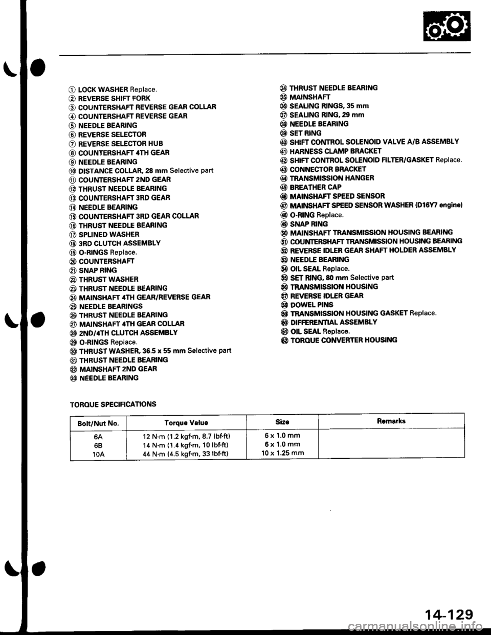
O LocK WASHER Replace,
O REVERSE SHIFT FORK
O COUNTERSHAFT REVERSE GEAR COLLAR
G) COUNTERSHAFT REVERSE GEAR
@ NEEDLE BEARING
@ REVERSE SELECTOR
O REVERSE SELECTOR HUB
@ COUNTERSHAFT 4TH GEAR
O NEEDLE BEARING
@ DISTANCE GOLLAR, 28 mm Selective part
O COUNTERSHAFT 2ND GEAR
@ THRUST NEEDIE BEARING
@ COUNTERSHAFT 3RD GEAR
@ NEEDLE BEARING
@ COUNTEBSHAFT 3RD GEAR COLLAR
@ THRUST NEEDLE BEAFING
O SPLINED WASHER
@ 3RD CLUTCH ASSEMBLY
@ O-RtNGs Replace.
@ COUNTERSHAFT
@ SNAP RING
@ THRUST WASHER
€) THRUST NEEDTE BEARING
@} MATNSHAFT 4TH GEAR/REVERSE GEAR
@i NEEDLE BEARINGS
@ THRUST NEEDLE EEARING
@) MAINSHAFT 4TH GEAR COLLAR
@ 2ND/4TH CLUTCH ASSEMBLY
@ o-RlNGs Replace.
@ THRUST WASHER,36.5 x 55 mm Sel€ctive part
@ THRUST NEEDLE BEARING
@ MAINSHAFT zND GEAR
@ NEEDLE BEARING
@ THRUST NEEDLE BEARING
@ MAINSHAFI
@ S€ALING RINGS, 35 mm
@ SEALING RING,29 mm
@} NEEDIE BEARING
@ SET RING
@ sHrFT CONTROL SOLENOID VALVE A/B ASSEMSLY
@ HARNESS CLAMP BRACKET
@ SHIFT COI,ITROL SOI"ENOID FILTER/GASKET Replace.
@ CONNECTOR BFACKET
@D TNANSMISSION HANGER
@ BREATHER CAP
@ MAINSHAFT SPEED SENSOR
@ MATNSHAFT SPEED SENSOR WASHER {Dl6Y' ongine}
@ O-RING Replace.
@ SNAP RING
@ MAINSHAFT TRANSMISSION HOUSING BEARING
@ OOUNIERSHAFT TRANSMISSION HOUSING BEARING
@ REVERSE IDLER GEAR SHAFT HOLDER ASSEMBLY
@ NEEDI.E BEARING
@ olL SEAL Replace.
@ SET RING, fll mm Selective part
@ rnANsMrssloN HouslNG
@ REVERSE IDI."ER GEAR
@ DowEL PINS
@ TRANSMISSION HOUSING GASKET Replace.
@ DIFFERENfIAL ASSEMBLY
@ OIL SEAL Replace.
@ TOROUE CONVERTER HOUSING
TOROUE SPECIFICANONS
Boh/Nut No.Torquo valueSizeRomarks
6B
10A
12 N.m {1.2 kgf.m,8.7 lbf.ft)
14 N.m (1.4 kgf'm, 10lbf'ft)
44 N.m (4.5 kgf.m, 33 lbf'ft)
6x1.0mm
6x1.0mm
10 x 1.25 mm
14-129