Page 193 of 2189
Rocker Arms
lnstallation
1.
2.
3.
lnstall the rocker arms in the reverse order of
removal:
. Valve adjusting locknuts should be loosened and
the adiusting screw, backed off before installa-
tron.
. The component parts must be reinstalled in the
original locations.
lnstall the lost motion assemblies.
lnstall the rocker arms while inserting the rocker
arm shaft into the cylinder head
NOTE: Remove the rubber band after installing the
rocker arms.
12 mm BOLT
\
6-83
4. Clean and install the rocker shaft orifices with new
O-rings. lf the holes in the rocker arm shaft and
cylinder head are not in line with each other, screw
a 12 mm bolt into the rocker arm shaft and rotate
the shaft.
NOTE: The shapes of the rocker shaft orifices tor
the intake and exhaust are different. The orific'
must be installed in the proper locations.
INTAKE ROCKER
SHAFT ORIFICE
EXHAUST ROCKER Clean
SHAFT ORIFICE
O.RING
O
Page 211 of 2189

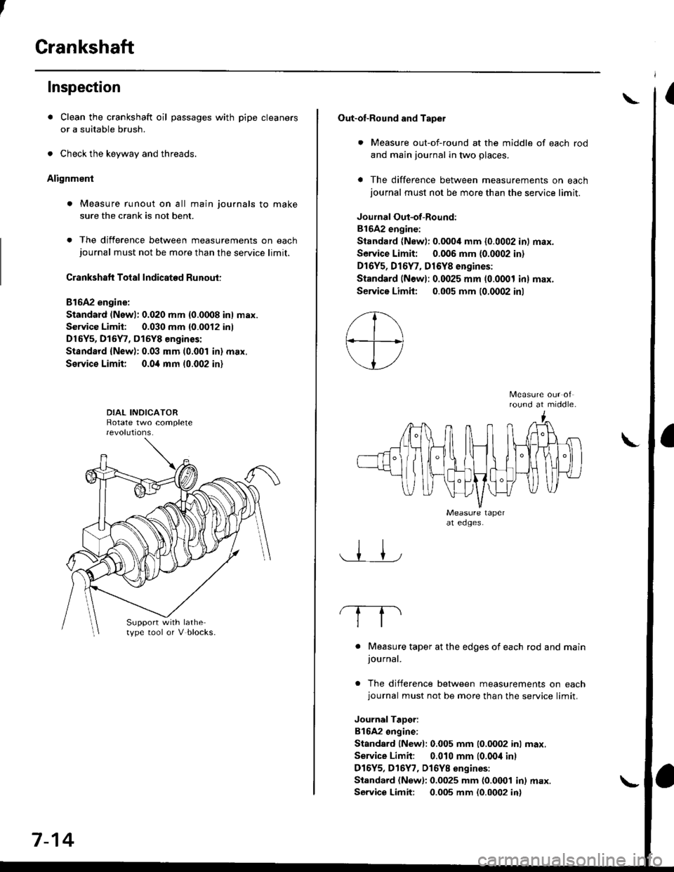
Crankshaft
Inspection
. Clean the crankshaft oil passages with pipe cleaners
or a suitable brush.
. Check the keyway and threads.
Alignment
. Measure runout on all main journals to make
sure the crank is not bent.
. The difference between measurements on eachjournal must not be more than the service limit.
Crankshaft Total Indicated Runout:
Bl6A2 engine:
Standard (Newl: 0.020 mm {0.0008 in} max.
Service Limit: 0.030 mm {0.0012 inl
D16Y5, D15Y7, D15Y8 engines:
Standsrd {New): 0.03 mm (0.001 in} max.
Service Limit; 0.0i1 mm 10.002 in)
Support with lathetype tool or V blocks.
7-14
Out-of-Round and Tapet
. Measure out-of-round at the middle of each rod
and main journal in two places.
a The difference between measurements on eachjournal must not be more than the service limit.
Joulnal Out-of-Round:
81642 engine:
Standard (New): 0.0004 mm {0.0002 in) max.
Service Limit: 0.006 mm {0.0002 in)
Dr6Y5, Dl6Y7, D16Y8 engines:
Standard (Newl: 0.0025 mm (0.0001 inl max.
Service Limh: 0.005 mm (0.0002 inl
round at middle.
. Measure taper at the edges of each rod and mainjournal.
. The difference between measurements on eachjournal must not be more than the service limit.
JournalTaDer:
B16A2 ongine:
Standard lNewl: 0.005 mm (0.0002 inl max.
Service Limit: 0.010 mm (0.00i1 inl
D16Y5, D16Y7, Dl6YB engines:
Standard (New): 0.0025 mm {0.0001 in) max.
Service Limit: 0.005 mm (0.0002 in)
\
Page 212 of 2189

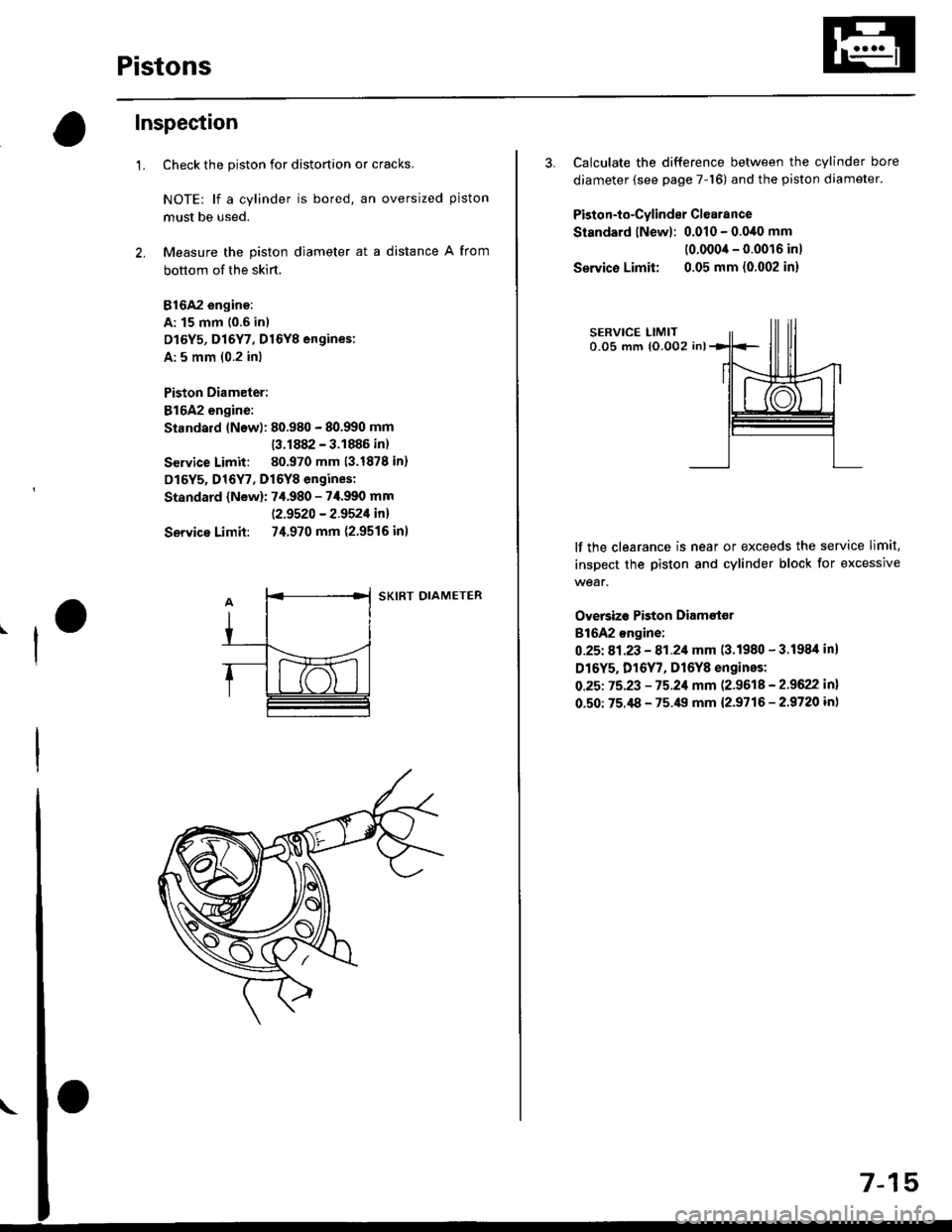
Pistons
Inspection
1.Check the piston for distortion or cracks,
NOTE: lf a cylinder is bored. an oversized piston
must be used.
Measure the piston diameter at a distance A from
bottom of the skirt.
816A2 engino:
A: 15 mm 10.6 in)
D16Y5, D16Y7, D16Y8 engines:
A: 5 mm (0.2 inl
Piston Diameter:
816A2 engine:
Standard lNewl: 80.980 - 80.990 mm
13.1882 - 3.1886 in)
Service Limit: 80.970 mm (3.1878 in)
D16Y5, D16Y7, D16Y8 engines:
Standard {New): 7,f.980 - 7i1.990 mm
|.2.9520 - 2.9521in!
Service Limit: 74.970 mm {2.9516 inl
SKIRT DIAMETER
57-1
3. Calculate the difference between the cylinder bore
diameter (see page 7-16) and the piston diameter.
Piston-to-Cylinder Clsarance
Standard lNewl: 0.010 - 0.0,10 mm
(0.0004 - 0.0016 inl
Servico Limit: 0.05 mm {0.002 in}
lf the clearance is near or exceeds the service limit,
inspect the piston and cylinder block for excessive
wear.
Oversizo Piston Diametor
816A2 ongine:
0.25t 81.23 - 81.21 mm (3.1980 - 3.1984 inl
D16Y5. D16Y7, D16Y8 engines:
O.25t 75.23 - 75.21 mm (2.9618 - 2.9622 in)
0.50: 75.i18 - 75.49 mm {2.9716 - 2.9720 in}
Page 213 of 2189

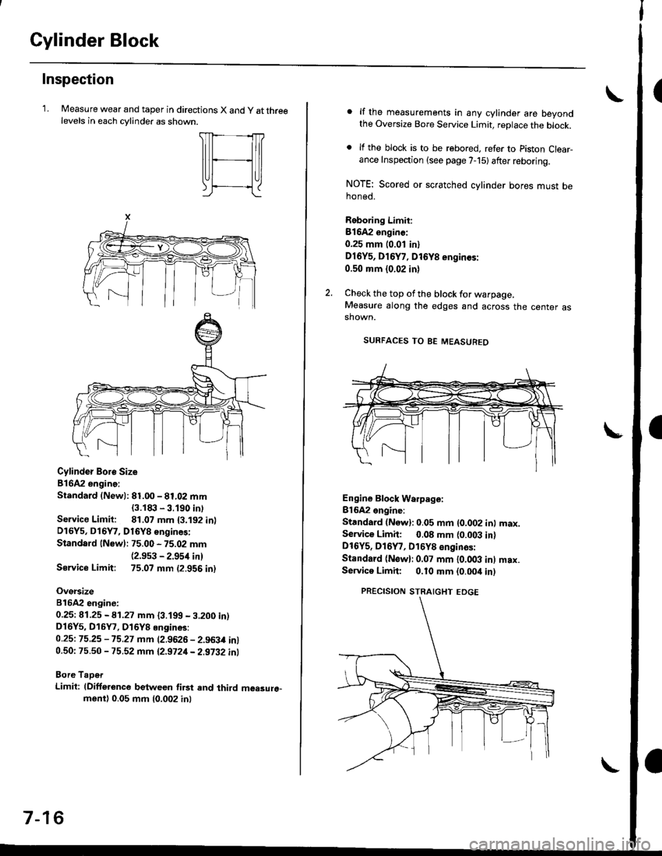
Cylinder Block
Inspection
'LMeasure wear and taper in directions X and y at threelevels in each cvlinder as shown.
Cylinder Boro Size
816A2 engine:
Standard (Newl: 81.00 - 81.02 mm
{3.1t|:l - 3.190 intService Limit: 81.07 mm {3.192 in)D16Y5, D16Y7, D16Y8 engines:
Standard lNew): 75.00 - 75.02 mm(2.9s3 - 2.954 in)
Sarvice Limit: 75.07 mm (2.956 in)
Oversize
816A2 engiDe:
0.25t 41.25 - A1.27 mm {3.199 - 3.200 in)D16Y5, D16Y7, D16Y8 Engines:
0.25t 75.25 -15.27 mm (2.9626 - 2.963,0 in)0.50: 75.50 - 75.52 mm 12.9721- 2.9i32 inl
Bore TaDet
Limit: (Difference between first and third measure"ment) 0.05 mm (0.002 inl
7-16
lf the measurements in any cylinder are beyondthe Oversize Bore Service Limit, replace the block.
lf the block is to be rebored. refer to piston Clear-ance Inspection (see page 7-15) after reboring.
NOTE: Scored or scratched cylinder bores must behoned.
Reboring Limit:
Bl642 enginc:
0.25 mm (0.01 in)
Dl6Y5, D16Y7, D16Y8 engin€s:
0.50 mm (0.02 in)
Check the top of the block for warpage,Measure along the edges and across the center asshown.
SURFACES TO BE MEASUREO
Engine Block Warpage:
Bl6A2 engine:
Standard (Now): 0.05 mm {0.002 inl max.Service Limh: 0.08 mm (0.003 in)DtOYs, D16Y7, D16Y8 €nginas:
Standard (N€w): 0.07 mm l0.OO3 inl max.Servica Limit; 0.10 mm {0.00it in)
PRECISION STRAIGHT EDGE
Page 216 of 2189

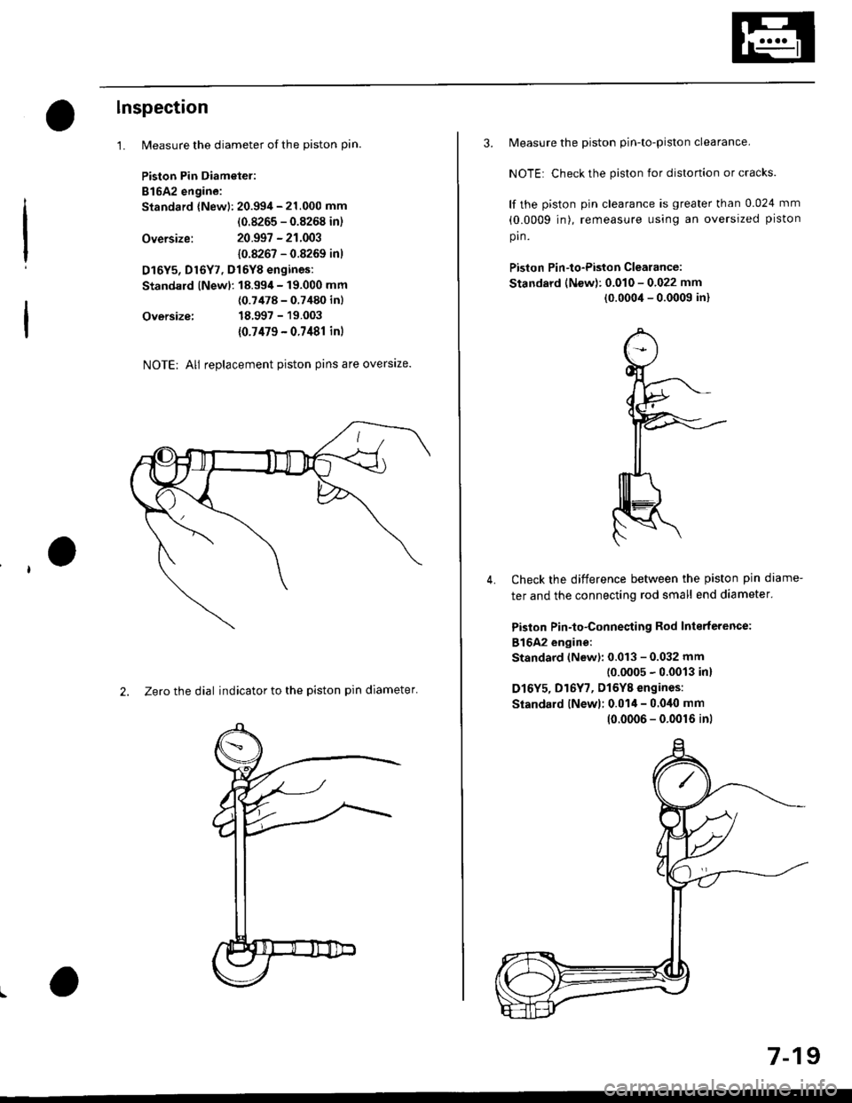
lnspection
1.
Oversize:
Oversize:
NOTE; All replacement piston pins are overslze.
2. Zero the dial indicator to the piston pin diameter'
Measure the diameter of the piston pin.
Piston Pin Diametel:
B16A2 engine:
Standard {New): 20.994 - 21.000 mm
(0.8265 - 0.8268 in)
20.997 - 21.003
10.8267 - 0.8269 inl
D16Y5, Dl6Y7, Dl6YB engines:
Standard lNewl: 18.99,1- 19.000 mm
(0.7478 - 0.7480 inl
18.997 - 19.003
{0.7479 - 0.7481 in)
3. Measure the piston pin-to-piston clearance.
NOTE: Check the piston for distortion or cracks.
lf the piston pin clearance is greater than 0.024 mm
(0.0009 jn), remeasure using an oversized piston
pin.
Piston Pin-to-Piston Clearance:
Standard (New): 0.010 - 0.022 mm
(0.0004 - 0.0009 in)
Check the difference between the piston pin diame-
ter and the connecting rod small end diameter'
Piston Pin-to-Connesting Rod Interterence:
816A2 engine:
Standard (New): 0.013 - 0.032 mm(0.0005 - 0.0013 in)
D16Y5, D16Y7, Dl6YB engines:
Siandard lNewl; 0.014 - 0.040 mm
4.
10.0006 - 0.0016 inl
7-19
Page 320 of 2189

System Connectors [Fuel Pumpl
'95 - 98 models, '99 - 00 Dl6Y5 engine with M/T:
ffi
c565
E
c792*r,.'5c793|.,.s
*1r USA mod€l'2: A/T {O16Y7, D16Y8 ensine}13: CVT {O16Y5 ensin€l*4: A/T ind D16Y7 .ngane*5: ExceFt A/T end D16Y7 engine'6: A/T lDl6Y8 enginel*7: CvT (Dl6Y5 enginoland 016Yg engine'8: ,96 Dl6YB engine {coupe),'97 Dl6Y8 sngine
{coupe: sll models, s€d.nr KL modell,'98 Dl5Y5.ngine,'98 D16Y7 engine,'99 - OO Dl6Y5 (M/Tl enginer9: D16Y5 onginet10: M/T {D15Y5 ensinelr1t: ExceDt M/T (D16Y5 engine)tl2: D16Y5, Dl6Yg engine*13: Dl6Y8 enginer14: D16Y7 engine*15:'97 Dl6Y7 ensine {coupe: KL model, sodan:
KL (LX) modeu,'98 Dt6Y7 engine
NOTE: . Different wires with the same color have been given a number suffix to distinguish them (for example' YEUBLK1
and YEVBLK'� are not the samel.
. O: Related to Fuel and Emissions System'
. - Connector with male terminals (dou ble outline): View f rom term inal side
- Connector with female terminals (single outline): View from wire side
c7931...15
ffi
1 1-51
Page 322 of 2189
Cl0,r{C.nadal
r'fr]
l6mrrrnru IElilrwA----llTltHtBtu__l
:lo.
l'lrl
lrl.l
c109..
r'frtr
16lonl -l
l@LYEUBLK' Ibfgl-rcgtu'---l
c102
r'Trtt
l6lwtr,eED' _-l
E|BFIvBLK -l
l6lga-tnEcl--l
c105
Etr
c106
ffi
c114
fr
c108
ffi
c107
ffi
Bffiffi
c113*1
ffiffi
,DGRN/BLK'(9LT GRN?BLU]38
NOTE: . Different wires with the same color have been given a number suffix to distinguish them (for 6xample, YEUBLK1
and YEUBLK'�are not the same).
. O: Related to Fuel and Emissions Syst€m'
. - Connector with male terminals (double outline): View from terminal side
- Connector with female terminals (single outline): View trom wire side
(cont'd)
11-53
c1a2.r
fr
Page 324 of 2189
![HONDA CIVIC 1997 6.G Workshop Manual c1t7
rffi]
fTBLir-llO BLX,YEI Il6lEtu^tHr__-l
c125
ffi
16lwrrin+o tliSlcFN/BLK I16T8LK^Er-- l
-.,IBaK,r /Hr. I
c141*
___l:t_
l-lrl
I LT GRNA/VHT I
f€,]-BLK,rEf-__l
cl16c1t5cl11
c128.
ffi
161 HONDA CIVIC 1997 6.G Workshop Manual c1t7
rffi]
fTBLir-llO BLX,YEI Il6lEtu^tHr__-l
c125
ffi
16lwrrin+o tliSlcFN/BLK I16T8LK^Er-- l
-.,IBaK,r /Hr. I
c141*
___l:t_
l-lrl
I LT GRNA/VHT I
f€,]-BLK,rEf-__l
cl16c1t5cl11
c128.
ffi
161](/manual-img/13/6068/w960_6068-323.png)
c1t7
r'ffi]
f'TBLir-llO BLX,YEI Il6lEtu^tHr__-l
c125
ffi
16lwrrin+o' tliSlcFN/BLK I16T8LK^'Er-- l
-.,IBaK,r /Hr. I
c141*'
___l:t_
l-lrl
I ' LT GRNA/VHT I
f€,]-BLK,rEf-__l
cl16c1t5cl11
c128.'
ffi
1618r-uf/EL-_]
161-cfl,avHr -l
cl45rrc
Ft_
l-,T,ITd
t_-Ttli I
c127*'
fr
IFFEc'--__l
ftlwHn-'_l
-c,1*
t-El-rl1 I 2l 3l
l.l
'ul
16lvvrrr/BtK---.llglcnN/BrK, IlO YEvBru I16r lsrK' IET- --
f+plr-, -_l
c118"
ffi
trl-clrl---]latl IBLU, I
c126*'
ffi
fOTwHn-_-llOlREo. I
:.trn
.EL
[tT,l.l
v
I i wHl/8tK IlETc RNi BLF--l
ET-YtrrrruBiu-__-l
q]54't
r,f,"|
I i IBLK4/VHT IlOlsLK I
IO LGRN/RED I
c112
fr
c120
tdl cnN/YEt--l
NOTE: . Different wires with the same color have been given a number suffix to distinguish them (for example, YEUBLK'
and YEUBLIC are not the same).
. O: Belated to Fuel and Emissions System'
. - Connector with male terminals (double outline): View from terminal side
- Connector with female terminals (single outlins): View from wire side {cont'd}
c121*'
ffi
c123
ffi
c1a0rt
fr
l6lgrf,---_-lIOIREB I
c13!,.f
E
c122
iYEUGFNoBLU5REO!8L(,
YEL'98tu
510BLK/YEL
c351
1 1-55