1997 HONDA CIVIC Diffe
[x] Cancel search: DiffePage 1075 of 2189
t
To STEERING GEARBOX
To STEERING GEAREOx
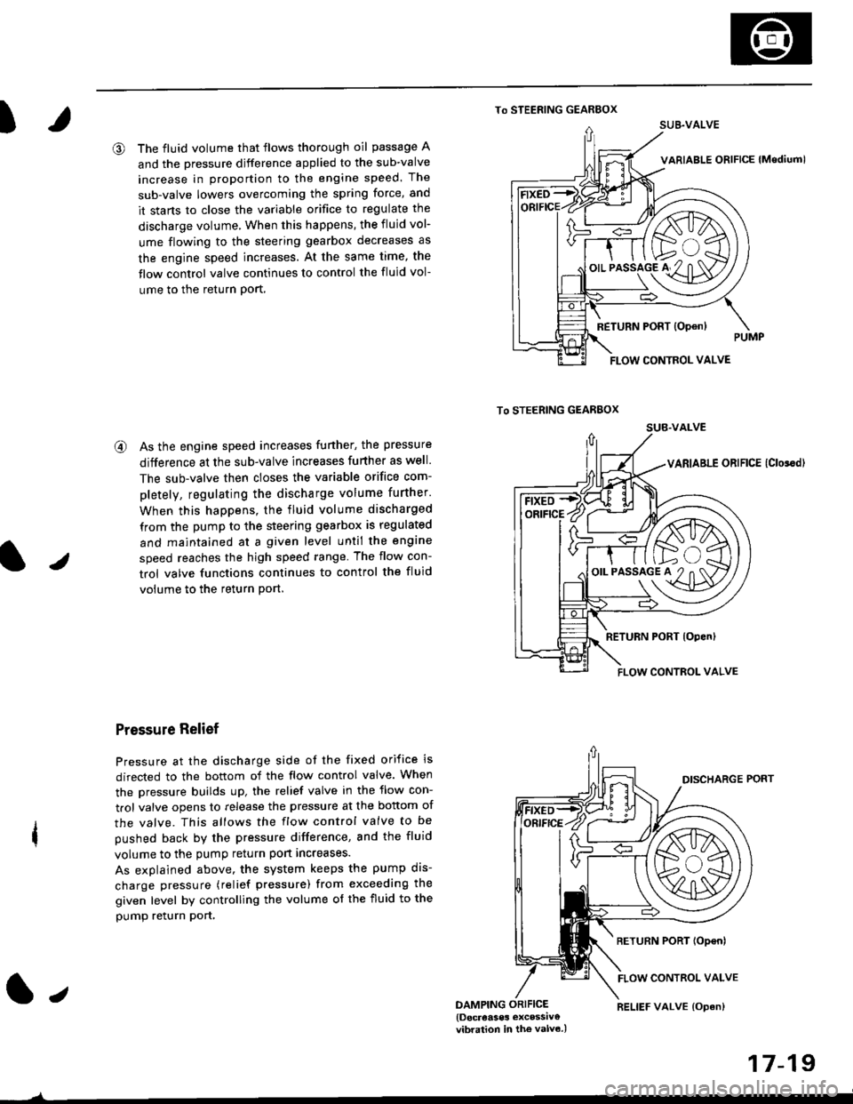
@ The fluid volume that flows thorough oil passage A
and the pressure djfference applied to the sub-valve
increase in proportion to the engine speed. The
sub-valve lowers overcoming the spring force, and
it stans to close the variable orifice to regulate the
discharge volume, When this happens, the fluid vol-
ume flowing to the steering gearbox decreases as
the engine speed increases. At the same time, the
flow control valve continues to control the fluid vol-
ume to the return Port,
@ As the engine speed increases funher, the pressure
difference at the sub-valve increases further as well.
The sub-valve then closes the variable orifice com-
pletely, regulating the discharge volume further.
When this happens, the fluid volume discharged
from the pump to the steering gearbox is regulated
and maintained at a given level until the engine
speed reaches the high speed range The flow con-
trol valve functions continues to control the fluid
volume to the return Port.
Pressure Relief
Pressure at the discharge side of the fixed orifice is
directed to the bottom of the flow control valve. When
the pressure builds up, the relief valve in the flow con-
trol valve opens to release the pressure at the bottom of
the valve. This allows the flow control valve to be
pushed back by the pressure difference, and the fluid
volume to the pump return port increases.
As explained above. the system keeps the pump dis-
charge pressure (relief pressure) from exceeding the
given level by controlling the volume of the fluid to the
pump relurn pon,
1.,DAMPING ORIFICE{Docreases excessiv€vibration in the valv6.)
17-19
)
RELIEF VALVE {Opan)
SUB.VALVE
FLOW CONTROL VALVE
/F ft>..\
'-€/K\A/A
o'.'to"5lo'#2"n af11\D7
FLOW CONTROL VALVE
Page 1076 of 2189
System Description
Steering Gearbox
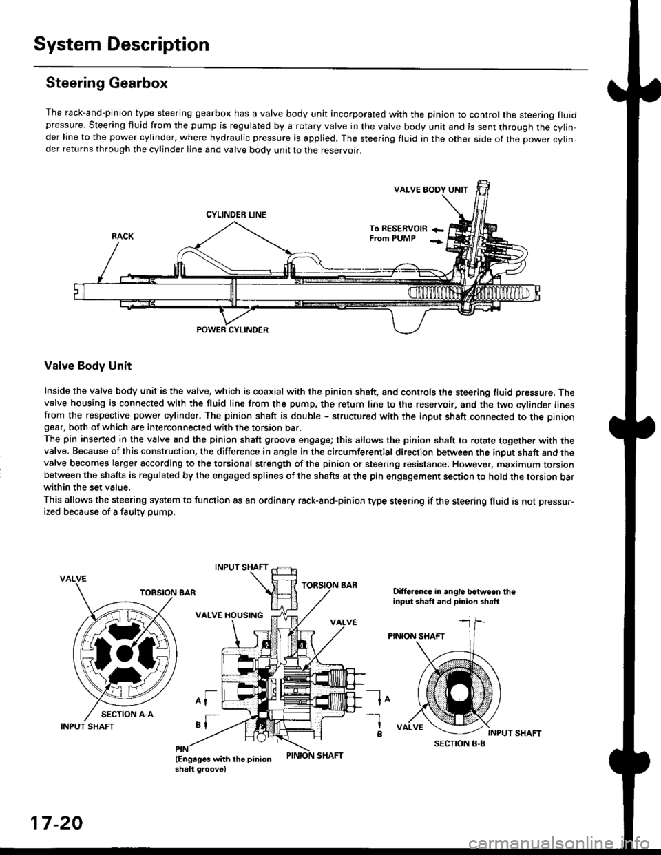
The rack-and-pinion type steering gearbox has a valve body unit incorporated with the pinion to control the steering fluidpressure. Steering fluid from the pump is regulated by a rotary valve in the valve body unit and is sent through the cylin,der line to the power cylinder, where hydraulic pressure is applied. The steering fluid in the other side of the power cylin,der returns through the cylinder line and valve body unit to the reservoii.
VALVE EODY UNIT
CYLINDER LINE
To RESERVOm +-From PUMP -;
POWER CYLINDER
Valve Body Unit
Inside the valve body unit is the valve, which is coaxial with the pinion shaft, and controls the steering fluid pressure. Thevalve housing is connected with the fluid line from the pump, the return line to the reservoir, and the two cylinder linesfrom the respective power cylinder. The pinion shaft is double - structured with the input shaft connected to the piniongear, both of which are interconnected with the torsion bar.
The pin inserted in the valve and the pinion shaft groove engage; this allows the pinion shaft to rotate together with thevalve. Because of this construction, the difference in angle in the circumferential direction between the input shaft and thevalve becomes larger according to the torsional strength of the pinion or steering resistance. However, maximum torsionbetween the shafts is regulated by the engaged splines of the shafts at the pin engagement section to hold the torsion barwithin the set value,
This allows the steering system to function as an ordinary rack-and-pinion type steering if the steering fluid is not pressur-
ized because of a faulty pump,
VALVE
Difforence in angle botwoon theinput shaft and pinion shsft
PINION SHAFT
lo
INPUT SHAFT
-l
a
17-20
INPUT SHAFT
Page 1077 of 2189
Pressure Control
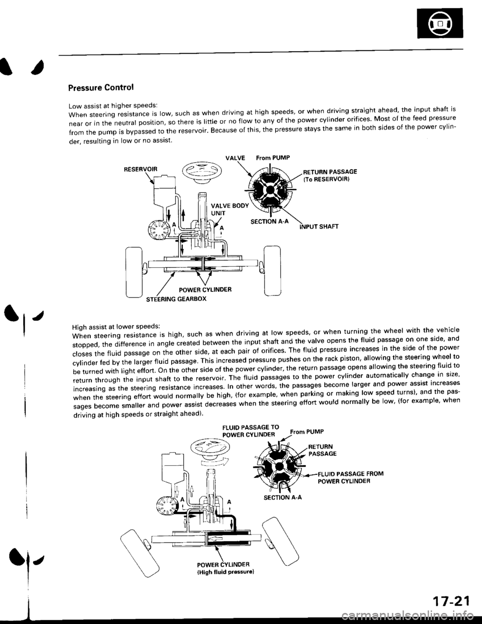
Low assist at higher speeds:
WhensteeringresistanceIsIow,suchaswhendrivingathighspeeds,orwhendrivingstraightahead,theinputshaftis
near or in the neutral position, so there is little or no fiow ro any of the power cylinder orifices. Most oI the feed pressure
fromthepumpisbypassedtothereservoir.Becauseofthis,thepressurestaysthesameinbothsidesofthepowercy||n-
der, resulting in low or no asslst
VALVE From PUMP
SECTION A-A
RETURN PASSAGElTo RESERVOIRI
POWER CYLINDER
STEERING GEARBOX
High assist at lower speeds:
When steering resistance is high. such as when driving at low speeds' or when turning the wheel wirh the vehicle
stopped,thedifference|nang|ecreatedbetweentheinputshaftandtheVa|veopensthef|uidpassageononeside,and
c|osesthefluidpassageontheotherside,ateachpairoforifices'Thef|uidpressureincreasesinthesideo|thepower
cy|inder|edbythe|argerf|uidpassage'Thisincreasedpressurepushesontherackpiston,a|lowingthesteeringwhee|to
be turned with light effort. on the other side of the power cylinder, the return passage opens allowing the steering tluid to
returnthroUghtheinputshafttothereservoir'Thef|uidpassagestothepowercy|inderautomatica||ychangeins|ze,
increasing as the steering resrstance increases. In other words, the passages become larger and power assist increases
when the steering effort would normally be high, (for example' when parking or making low speed turns)' and the pas-
sagesbecomesma||erandpowerassistdecreaseswhenthesteeringeffortwou|dnorma||ybe|ow,(forexamp|e,when
driving at high speeds or straight ahead).
FLUIO PASSAGE TO
POWER CYLINDER
/t=\\a!-4,))
=YjJ
RESERVOIR
SECTION A-A
l'
{High fluid Pressure}
Page 1079 of 2189
I
AbnormalDeformed
Faulty cylinder lines
Adiustment OK
Faulty valve body unit
Normal
IICompair the steering to another alike
vehicle.
/
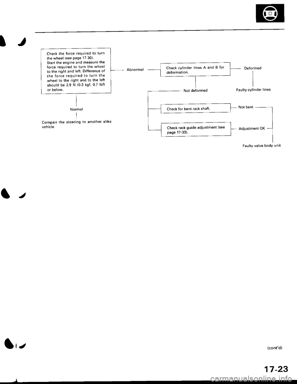
Check the force required to turn
the wheel (see Page 17 30i
Start the engine and measure the
force required to turn the wheel
to the right and left. Difference of
the lorce required to turn the
wheel to the right and to the Ieft
should be 2.9 N 10 3 kgf, 0.7 lbf)
or below.
Check for bent rack shaft
Check rack guide adiustment (see
page 17-33).
(cont'd)
17 -23
1,,
Page 1113 of 2189
I
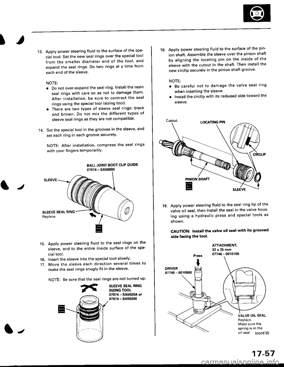
14.
Apply power steering fluid to the surface of the spe-
cial tool. Set the new seal rings over the special tool
from the smaller diameter end of the tool, and
expand the seal rings. Do two rings at a time from
each end of the sleeve.
NOTE;
. Do not over-expand the seal ring. Installthe resin
seal rings with care so as not to damage them'
After installation, be sure to contract the seal
rings using the specialtool (sizing tool).
. There are two types of sleeve seal rings: black
and brown. Do not mix the different types of
sleeve seal rings as they are not compatible
Set the special tool in the grooves in the sleeve, and
set each ring in each groove securely.
NOTE: After installation, compress the seal rings
with your fingers temPorarilY
BALL JOINT BOOI CLIP GUIDE
07S7,1- SA50800
SLEEVE
15. Apply power steering fluid to the seal rings on the
sleeve, and to the entire inside surface of the spe-
cial tool.
16. lnsert the sleeve into the specialtool slowly'
17. Move the sleeve each direction several times to
make the seal rings snugly fit in the sleeve'
NOTE: Be surerings are not turned uP.
SITEVE SEAL RINGSIZING TOOL0797a - SA5020A or07974 - SA50200
that the seal
fr
J
17-57
18. Apply power steering fluid to the surface o{ the pin-
ion shaft. Assemble the sleeve over the pinion shaft
by aligning the locating pin on the inside of the
sleeve with the cutout in the shaft. Then install the
new circlip securely in the pinion shaft groove'
NOTE:
Be careful not to damage the valve seal ring
when inserting the sleeve.
Installthe circlip with its radiused side toward the
sleeve.
Apply power steering fluid to the seal ring lip of the
valve oil seal. then install the seal in the valve hous-
ing using a hydraulic press and special tools as
shown.
CAUTION: Install the valve oil seal with its grooved
side facing the tool.
'19.
ATTACHMENT.32x35mm0774.6 - q)101(x)Pre3s
IDRIVER07749 - 0010000
VALVE OIL SEALReplace.Make sure thespring is in the
oil seal. (cont'd)
Page 1129 of 2189
?
Front Toe Inspection/Adiustment
NOTE: Use commercially-available computerized four
wheel alignment equipment to measure wheel align-
ment (caster, camber, toe, and turning angle). Follow
the equipment manufacturer's instructions.
1. Check the tire pressure.
Center steering wheel spokes.
Check the toe with the wheels pointed straight
a head.
Front toe: lN 1 1 2 mm llN l/16 r 1/16 inl
- lf adjustment is required, go on to step 4.
- lf no adjustment is required, remove alignment
equrpmenr.
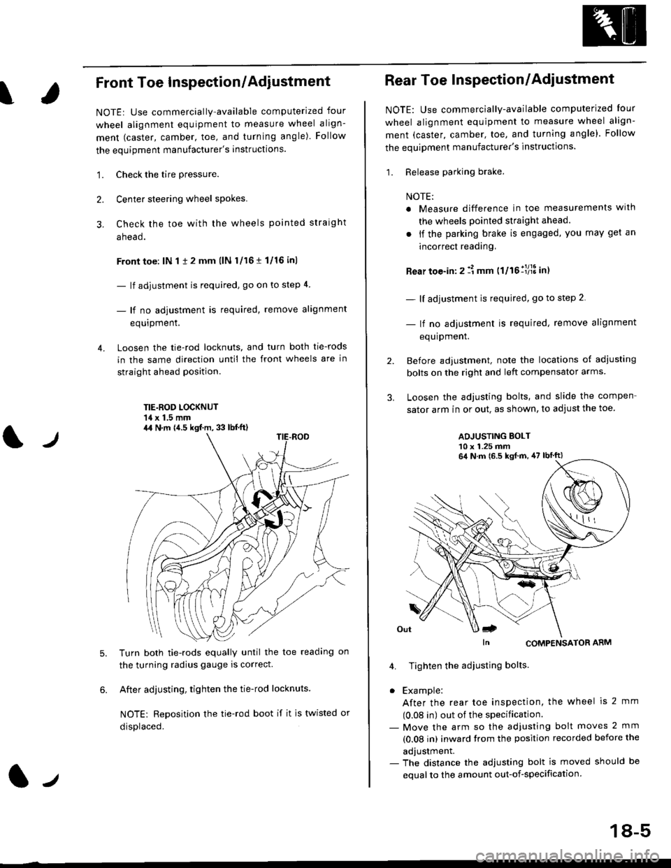
Loosen the tie-rod locknuts, and turn both tie-rods
in the same direction until the front wheels are in
straight ahead position.
TIE.ROD LOCKNUT'14 x 1.5 mm
4.
tJ
6.
Turn both tie-rods equally until the toe readang on
the turning radius gauge is correct.
After adjusting, tighten the tie-rod locknuts.
NOTE: Reposition the tie-rod boot if it is twisted or
displaced.
4,1 N.m {4.5 kgf.m, 33 lb{.ft)
2.
Rear Toe Inspection/Adiustment
NOTE: Use commercially-available computerjzed Iour
wheel alignment equjpment to measure wheel align-
ment (caster, camber, toe, and turning angle). Follow
the equipment manufacturer's instructions.
1. Release parking brake.
NOTE:
a Measure difference in toe measurements wlth
the wheels pointed straight ahead.
. if the parking brake is engaged, you may get an
incorrect readang,
Rear toe-in: 2 11 mm ttltollllS int
- lf adjustment is required, go to step 2.
- lf no adjustment is required, remove alignment
equipment.
Before adjustment, note the locations of adiusting
bolts on the right and left compensator arms
Loosen the adjusting bolts, and slide the compen
sator arm in or out. as shown, to adjust the toe
ADJUSTING BOLT10 x 1.25 mm
In CoMPENSAToR ARM
4. Tighten the adiusting bolts
. Example:
After the rear toe inspection, the wheel is 2 mm
(0.08 in) out of the specification.- Move the arm so the adjusfing bolt moves 2 mm
(0.08 in) inward trom the position recorded before the
adjustment.- The distance the adjusting bolt is moved should be
equal to the amount out-of-specification.
64 N.m 16.5 ksf m, 47 lbtft)
18-5
Page 1158 of 2189
Inspection and Adjustment
€)
@
@
@
Brake System Rubber Parts and Brake Booster
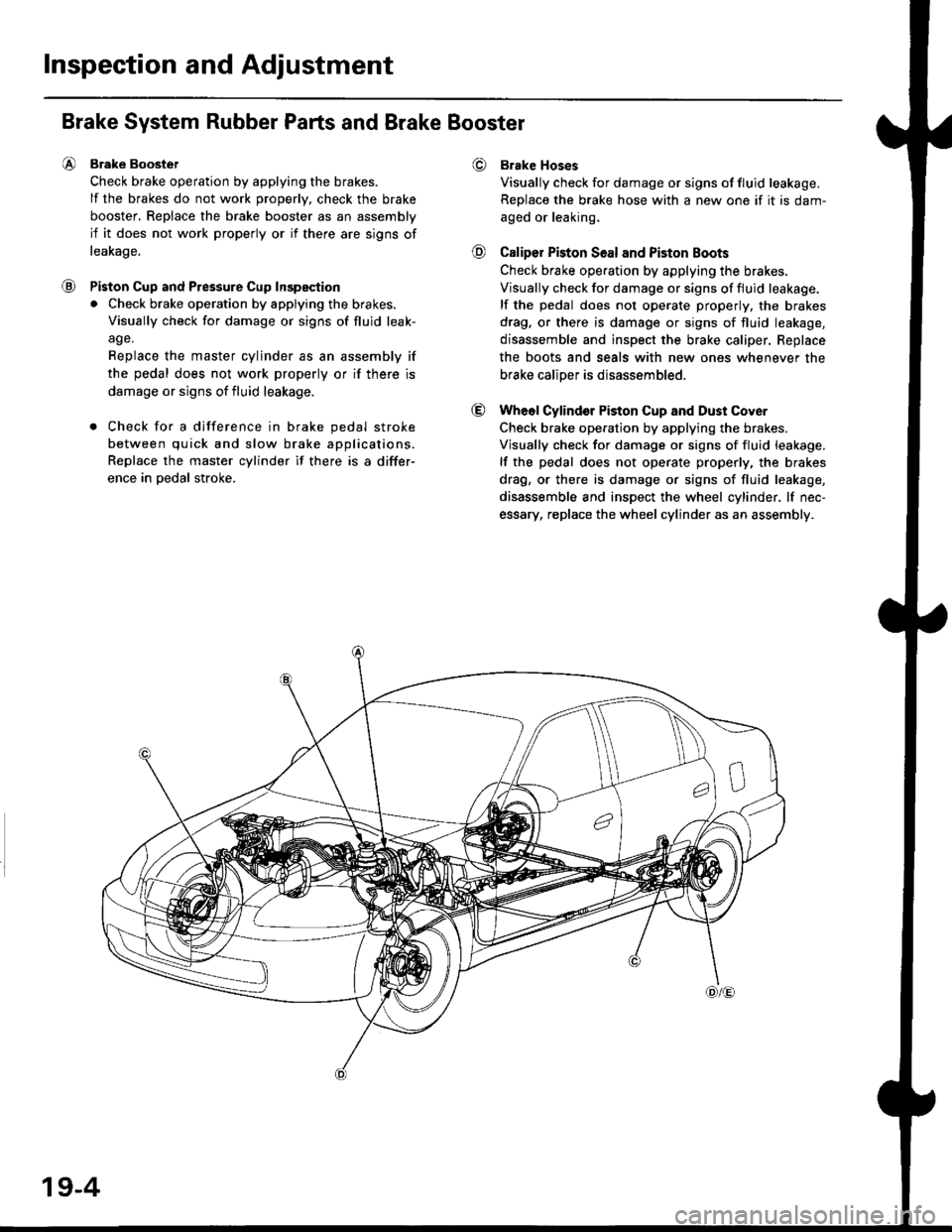
Brake Boostet
Check brake operation by applying the brakes.
lf the brakes do not work properly, check the brake
booster, Replace the brake booster as an assembly
if it does not work properly or if there are signs of
leakage.
Piston Cup and Pressure Cup Inspeqtion
. Check brake operation by applying the brakes.
Visually check for damage or signs of fluid leak-
age.
Replace the master cylinder as an assembly if
the pedal does not work properly or if there is
damage or signs of fluid leakage.
. Check for a difference in brake pedal stroke
between quick and slow brake applications.
Replace the master cylinder if there is a differ-
ence in oedal stroke.
Brake Hoses
Visually check for damage or signs of fluid leakage.
Replace the brake hose with a new one if it is dam-
aged or leaking.
Caliper Piston Seal and Piston Boots
Check brake ope.ation by applying the brakes.
Visually check for damage or signs of fluid leakage.
lf the pedal does not operate properly, the brakes
drag. or there is damage or signs of fluid leakage,
disassemble and inspect the brake caliper. Replace
the boots and seals with new ones whenever the
brake caliDer is disassembled.
Wheol Cylindor Piston Cup and Dust Cover
Check brake operation by applying the brakes.
Visually check for damage or signs of fluid leakage.
lf the pedal does not operate properly, the brakes
drag, or there is damage or signs of fluid leakage,
disassemble and inspect the wheel cylinder. lf nec-
essary, replace the wheel cylinder as an assembly.
19-4
Page 1166 of 2189
Front Brake Disc
Disc Runout Inspection
L
2.
Loosen the front wheel nuts slightly, then raise the
vehicle, and support it on safety stands. Remove
the front wheels.
Remove the brake pads (see page 19,8).
Inspect the disc surface for damage and cracks.
Clean the disc thoroughly and remove all rust.
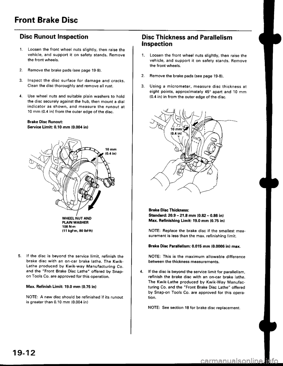
Use wheel nuts and suitable plain washers to hold
the disc securely against the hub, then mount a dial
indicator as shown, and measure the runout at
10 mm (0.4 in) from the outer edge of the disc.
Brake Disc Runout:
Service Limit: 0.10 mm (0.004 inl
WHEEL NUT ANOPLAIN WASHER'108 N.m(11 kg{.m, 80 lbf.ft)
lf the disc is beyond the service limit, refinish thebrake disc with an on-car brake lathe, The Kwik-Lathe produced by Kwik-way Manufacturing Co.and the "Front Brake Disc Lathe" offered by Snap-on Tools Co. are approved for this operation.
Max. Refinish Limit: 19.0 mm (0.75 in)
NOTE: A new disc should be refinished if its runout
is greater than 0.10 mm (0.004 in)
19-12
Disc Thickness and Parallelism
Inspection
1.Loosen the front wheel nuts slightly, then raise the
vehicle, and support it on safety stands. Remove
the front wheels.
Remove the brake pads (see page 19-8).
Using a micrometer, measure disc thickness at
eight points, approximately 45" apart and 10 mm(0.4 in) in from the outer edge of the disc.
Brake Dbc Thickn6s:
Standlrd: 20.9 - 21.8 mm (0.82 - 0.86 in)
Max. Refinishing Limit: 19.0 mm 10.75 inl
NOTE: Replace the brake disc if the smallest mea-
surement is less than the max. refinishinq limit.
Brake Disc Parallelism: 0.015 mm (0.fit06 in) max.
NOTE: This is the maximum allowable difference
between the thickness measurements.
lf the disc is beyond the service limit for parallelism,
refinish the brake disc with an on-car brake lathe.
The Kwik-Lathe produced by Kwik-Way Manufac-
turing Co. and the "Front Brake Disc Lathe" offered
by Snap-on Tools Co. are approved for this opera-
tion.
NOTE: See section 18 for brake disc reDlacement.