1997 HONDA CIVIC Rear lower arm
[x] Cancel search: Rear lower armPage 521 of 2189
Emission Gontrol System
System Description
The emission control system includes a Three Way Cata-lytic Convener (TWC), Exhaust Gas Recirculation (EGR)
system,. Positive Crankcase Ventilation (pCV) system andEvaporative Emission (EVAP) Control system. The emis-sion control system is designed to meet federal and stateemission standards.*: D16Y5 engine
Tailpipe Emission
Inspestion
@@ Do not smoke during ihis procedure. Keepany open flame away from your work area.
1. Start the engine. Hold the engine at 3,000 rpm withno load (in Park or neutral) until the radiator fancomes on. then let it idle.
2. Connect a tachometer.
Check and, if necessary, adjust the idle speed (see
page 11-220 - 223).
Warm up and calibrate the CO meter according to themeter manufacturer's instructions.
Check idle CO with the headlights, heater blower,rear window defogger, cooling fan, and air condition-er off.
NOTE: (Canada) Pull the parking brake lever up.Start the engine, then check that the headlights areoff.
CO mete. should indicate 0.1% maximum.
NOTE: '98 Dl6Y5 engine - lf the idle speed incress-es to 8101 50 rpm, this means the EVAp system ispurging the canister. To stop the purging temporari-ly. raise the engine speed above 1,000 rpm with theaccelerator pedal, then slowly release the pedal.
11-252
eFORWARD -
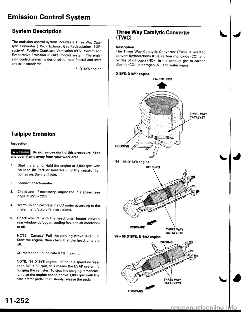
Three Way Catalytic Converter
(TWCI
Doscription
The Three Way Catalytic Converter (TWC) is used toconven hydrocarbons (HC), carbon monoxide (CO), andoxides of nitrogen (NOx) in the exhaust gas to carbondioxide (COr), dinitrogen (N,) and water vapor.
D15Y5, D16
, engine:
'99 - 00 D16Y8, 81642 engine:
ENGINE SIDE
t
Page 588 of 2189
Transmission Assembly
Removal(cont'd)
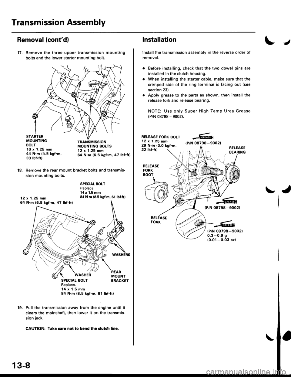
17. Remove the three upper transmission mounting
bolts and the lower starter mounting bolt,
STARTERMOUNTINGBOLT10 x 1.25 mm44 N.m (4.5 kgf.m,33 rbnftl
TRANSMISSIONMOUI{TING EOLTS12 x 1.25 mm& N.m (6.5 kgt'm,47 lbl.ftl
18. Remove the rear mount bracket bolts and transmis-
sion mounting bolts.
12 x 1.25 mm64 N.ft 16.5 kgl.m,47 lbl.ftl
SPECIAL BOLTReplace.'ll x 1.5 mm84 N.m (8.5 kgf.m, 61 lbf.ftl
SPECIAL BOLTReplace.14 x 1,5 mln84 N.m (8.5 kgl.m, 61
WASI{ERREARMOUNTBRACKET
rbl.ftt
Pull the transmission away from the engine until it
clears the mainshaft. then lower it on the transmis-
sion jack.
CAUTION: Take caro not to b6nd tho clutch lin€.
1(|
Installation
Install the transmission assembly in the reverse order of
removal.
Before installing, check that the two dowel pins are
installed in the clutch housing.
When installing the starter cable, make sure that the
crimped side of the ring terminal is facing out (see
section 23).
Apply grease to the parts as shown, then install the
release fork and release bearing,
NOTE: Use only Super High Temp Urea Grease
(P/N 08798 - 9002).
RELEASE FORK BOLT12 x 1.25 mm29 N'm 13.0 kgt,m,(P/N 08798-90021
22 tbl.ttlR€LEASEBEARING
J
RELEASEFORK8()07
ra
{PiN 08798-9002)
tP/N 08798-900210.3-0.9 g
10.01-0.03 ozl
Page 1125 of 2189
)
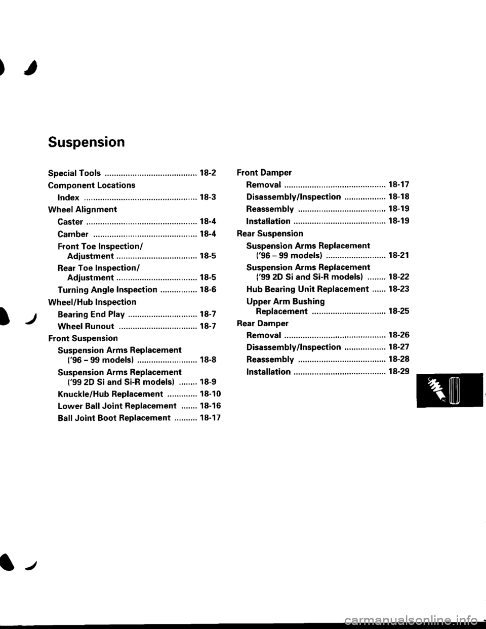
Suspension
Special Tools ............. 18-2
Component Locations
lndex ,,.............. ...... f8-3
Wheel Alignment
Caster .............. ....... 18-4
Camber .................. l8-4
Front Toe Inspection/
Adiustment ........ 18-5
Rear Toe lnspection/
Adiustment ........ 18-5
Turning Angle Inspection ................ 18-6
Wheel/Hub Inspection
Bearing End P|ay .............................. l8-7
Wheel Runout ....... 18-7
Front Suspension
Suspension Arms Replacement
('96 - 99 modelsl .......................... 18-8
Suspension Arms Replacement
('99 2D Si and Si-R models) ........ 18-9
Knuckle/Hub Replacement ............. 18-10
Lower Ball Joint Replacement ....... 18-16
Ball Joint Boot Replacement .......... 18-17
Front Damper
Removal ................. 18-17
Disassembly/1nspection .................. 18-18
Reassembly ........... 18-19
lnstallation ............. 18-19
Rear Suspension
Suspension Arms Replacement
('96 - 99 models) ....................,..... 18-21
Suspension Arms Replacement
('99 2D Si and Si-R models) ........ 1A-22
Hub Bearing Unit Replacement ...... 18-23
Upper Arm Eushing
Replacement .....18-25
Rear Damper
Removal ................. 18-26
Disassembly/|nspection ............. ..... 1A-27
Reassembly ........... 18-28
lnstallation ............. 18-29
lr
Page 1127 of 2189
Component Locations
)
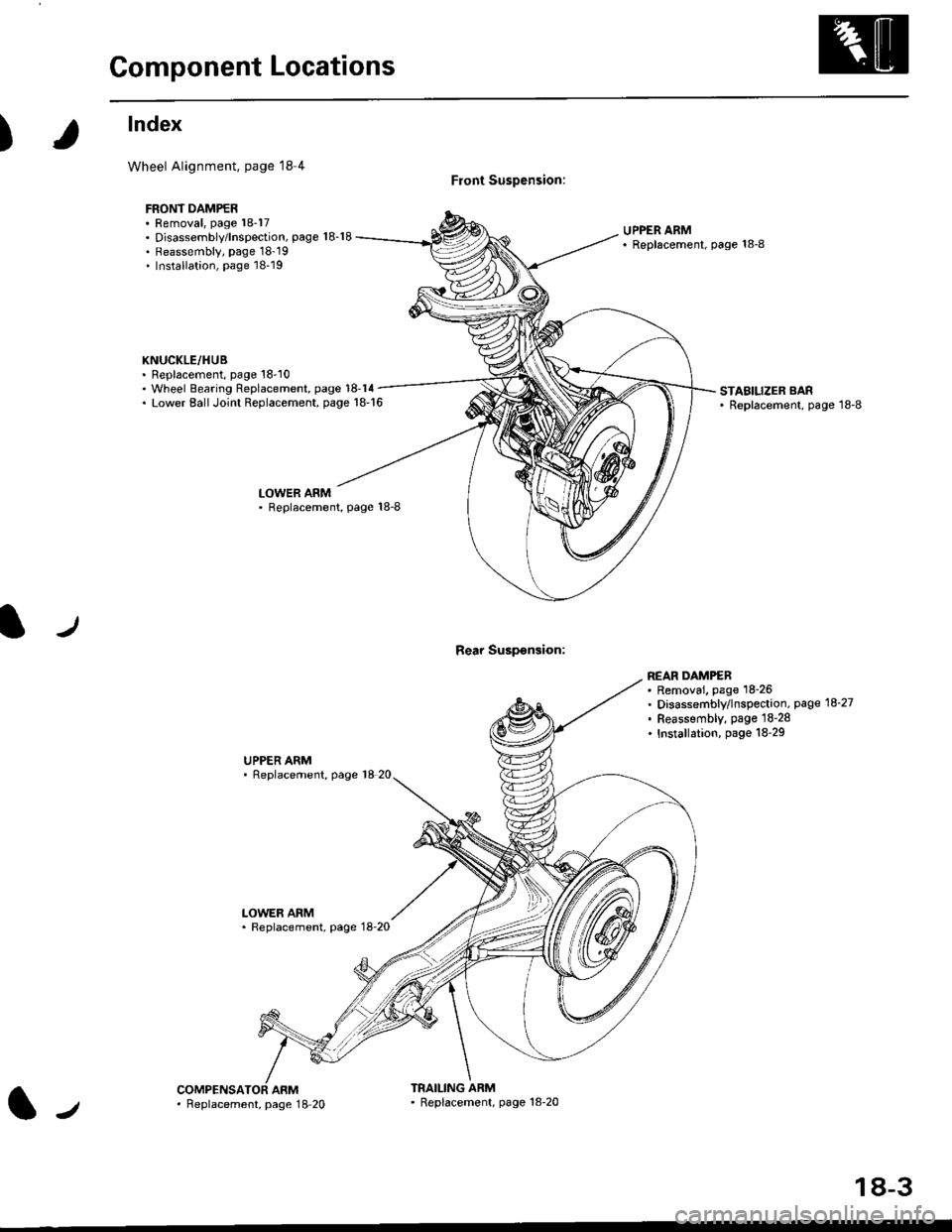
lndex
Wheel Alignment, page l8 4
FBONT DAMPER. Removal, page 18-17. Disassembly/lnspection, page 18-18. Reassembly, page 18'19. Installation, page 18-19
KNUCKLE/HUB. Replacement, page 18'10
Front Suspension:
Rear Suspsnsion:
UPPER ARM' Replscement, page 18-8
. Wheel Bearing Replacement, page 18-14. Lower EallJoint Replacement, page 18-16STABILIZER BAR' Replacement, page 18-8
LOWER ARM. Replacement, Page 18-8
UPPER ARM' Replacement, page 18 20
LOWER ARM. Replacement, page 18-20
REAR DAMPEB. Removai. page 18-26. Disassembly/lnspection, page 18-27. Feassembly, page lS-28. Installation, page 18-29
ARMTRAILING ARM' Replacement, page 18-20l-,. Feplacement, page 18 20
18-3
Page 1145 of 2189
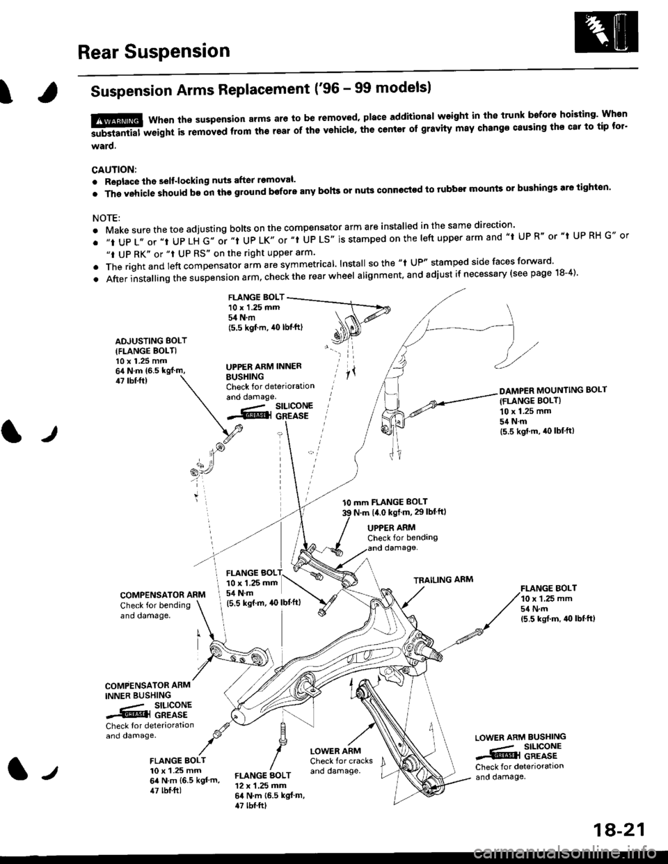
Rear Suspension
ISuspension Arms Replacement ('96 - 99 modelsl
tffi Whsn ths suspension arms ar6 to be removed. place additionsl weight in the trunk bafore hoisting' Wh€n
-substantial weight is removed ftom th6 teal of ths vehicl6, the center of gravity may change causing ths cat to tip tor'
ward.
CAUTION:
. Replace the selt-locking nuts after removal.
.Thgvehic|eshouldb€onthggroundboforeanybohsornutsconnectodtorubbelmountso]bughingsaretighton.
NOTE:
. Make sure the toe adjusting bolts on the compensator arm are installed in the same direction'
. ,,t UP 1,, or ,,t UP LH G,. or ,.t UP LK,, or "t UP LS'. is stamped on the |eft upper arm and ,,t UP R" or "t UP RH G., or
"t UP RK" or "t UP RS" on the right upper arm'
. The rightand left "ornp"n""to, uitt rre symmetrical lnstall sothe "t UP" stamped side faces forward'
.Afterinsta||ingthesuspens|onarm,checktherearwhee|alignment,andadjustifnecessary(seepagelS-4).
FLANGE BOLT10 x 1.25 mm54 N.m
ADJUSTING BOLT(FLANGE BOLTI10 x 1.25 mm
BUSHINGCheck for deteriorationand oamage.
(5.5 kgf'm, 40 lbf'ftl
UPPER ARM INNER
47 tbf.ftl
tJ
l0 mm FLANGE BOLT
N.m t4.0 kst m, 29lblftl
DAMPER MOUNTING BOLT(FLANGE BOLT}
10 x 1.25 mm
54Nm(5.5 kgd.m, iro lbf'ft)
FI.ANGE BOLT10 x 1,25 mm54 N.m(5,5 ksrf.m, 4{} lbf'ft}
UPPER ARMCheck for bendangdamage-
TRAILING ARM
COMPENSATOR ARM
Check for bendingano oamage,
COMPENSATOR ARM
INNER BUSHING
.- SILICONE.@] GREASE
Check tor deteriorataonand damage.
FLANGE BOLT10 x 1.25 mm64 N.m {6.5 kgt'm,47 lbf.ft)
LOWER ARMCheck for cracksano damage.
LOWEN ARM BUSHING
.,- SILICONE..i@l GREASECheck for deteriorationand oamage,FLANGE AOLT12 x 1.25 mm64 N.m {6.5 kgf m,47 tbf.ftt
FLANGE BOL10 x 1.25 mm
I 54 N.m
(5.5 ksrm, ao lbf'ftl
1A-21
Page 1146 of 2189
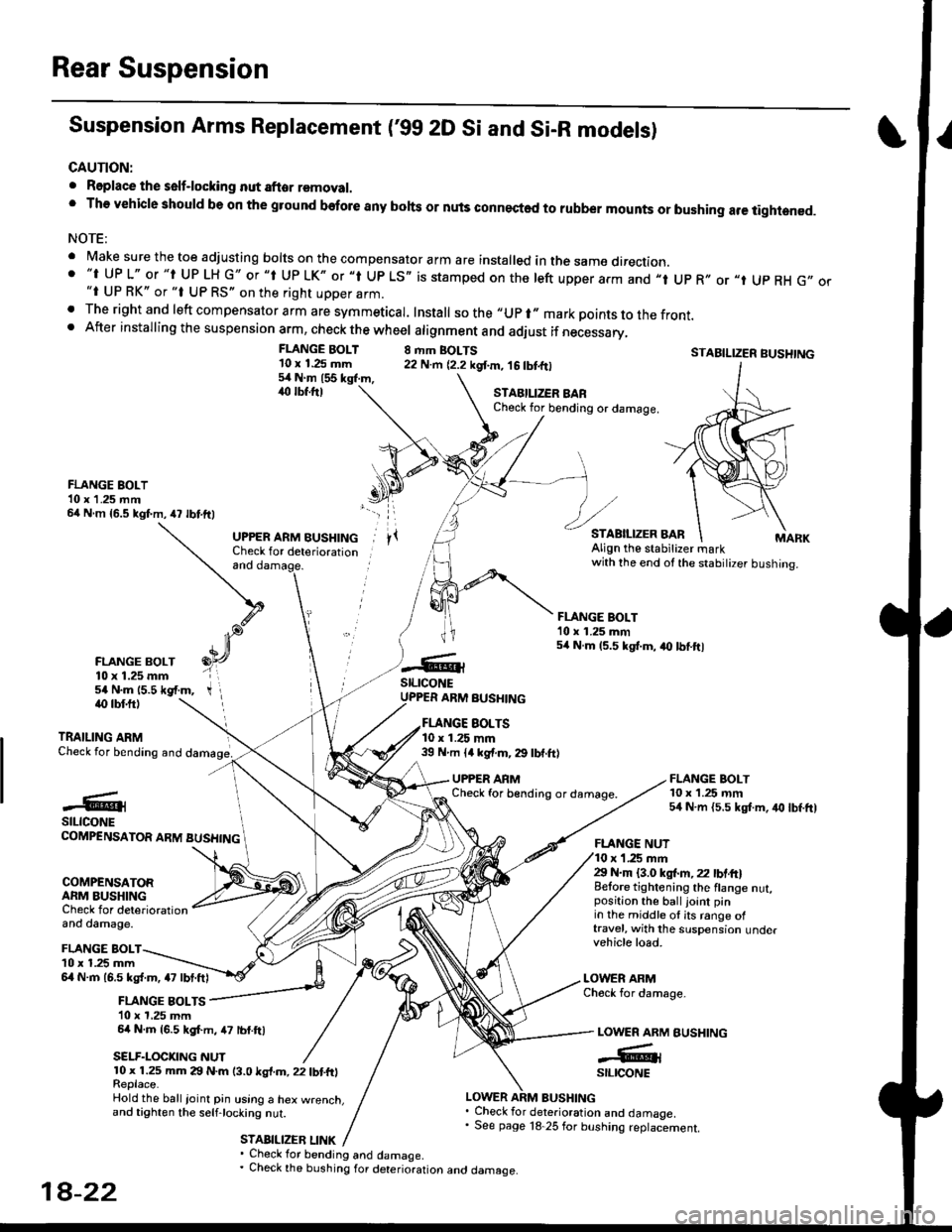
Rear Suspension
Suspension Arms Replacement ('gg 2D Si and Si-R models)
CAUTION:
. Roplace the self-locking nut after removal.' The vehicle should be on the gtound before any bohs or nuls connected to rubber mounts or bushing are tightened.
NOTE:
' Make sure the toe adjusting borts on the compensator arm are insta|ed in the same direction.. "t UP L" or "t UP LH G" or "t Up LK" or "l Up LS,, is stamped on the left upper arm and ,,t Up R,, or "t Up RH G,,"i UP RK" or "t UP RS" on the right upper arm.. The right and left compensator arm are symmeticar. Install sothe"upr"markpointstothefront.. After installing the suspension arm, check the wheel atignment and adiust if necessary,
FLANGE BOLT'10 x 1.25 mm54Nm155kgl.m,,rc lbf.ftl
8 rhm BOLTS22 N.m {2.2 kgf.m, 16 tbtfrlSTABILIZER BUSHTNG
FLANGE BOLT10 x 1.25 rnm54 N.m {5.5 kgt m, iro lbf.ft)
STAEILIZER BARCheck for bending or damage.
FLANGE BOLT10 x 1 .25 mm64 N m {5.5 kgf.m,47 lbtftl
FLANGE BOLT10 x 1.25 mm54 N.m 15.5 *gf.m,
and
UPPER ARM BUSHINGCheck for deteriorationAlign the stabitizer markwith the end ot the stabilizer bushing.
FLANGE BOLT'10 x 1.25 mm54 N.m 15.5 kgt.m, a0 lbtftl
stLrcoNEUPPER ARM BUSHINGiO lbf.ftl
TRAILING ARMCheck for bending and
EOLTS10 x 1.25 mm39 N m ll kgf.m, 29 lbf.ft)
UPPER ARMCheck for b€nding or damage.#@lstLtcoNECOMPENSATOR ARM BUSHING
COMPENSATORARM BUSHINGCheck for deteriorationand damage.
FLANGE NUTr '1.25 mm29 N.m {3.0 ksl.m,22 lbtft}Belore tightening the flange nut,position the ball joint pinin the middle ol its range oftravel, with the suspension undervehicle load.
LOWER ARMCheck for damage-
BUSHING
FLANGE BOLTl0 x 1.25 mm6l N.m 16.5 kg{.m, a7 lbt.ftl
FLANGE BOLTS10 x 1,25 mm64 N.m {6.5 kgf.m, 47 lbf.ftl
SELF.LOCKNG NUT
LOWER ARM
-GrstltcoNE10 x 1.25 mm 29 N.m (3.0 ksl.m, 22 tbtfrlReplace.Hold the ball ioinl pin using a hex w.enct.and tighten the selfjocking nut.
STABILIZEB LINK
LOWER ARM BUSHING. Check for deterioration and damaoe.' See page 18 25 for bushing replaciement.
' Check for bending and damage.. Check the bushing for deterioration ano oamage.
18-22
Page 1150 of 2189
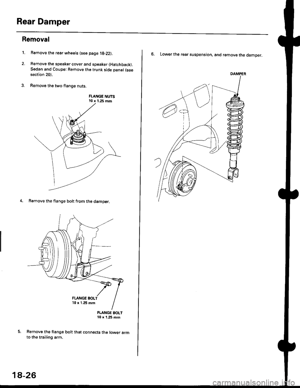
Rear Damper
Removal
1. Bemove the rear wheels (see page 1g-22).
2. Remove the speaker cover and speaker (Hatchback).
Sedan and Coupe: Remove the trunk side panel (see
section 20).
3. Remove the two flange nuts.
FLANGE NUTS10 x 1.25 mm
4. Remove
FLANGE BOLT10 x 1,25 mm
Remove the flange bolt that connects the lower armto the trailing arm.
the flange bolt from the damper.
FLANGE BOLT'10 x 1 .25 mm
18-26
6. Lower the rear suspension, and remove the damper.
Page 1266 of 2189
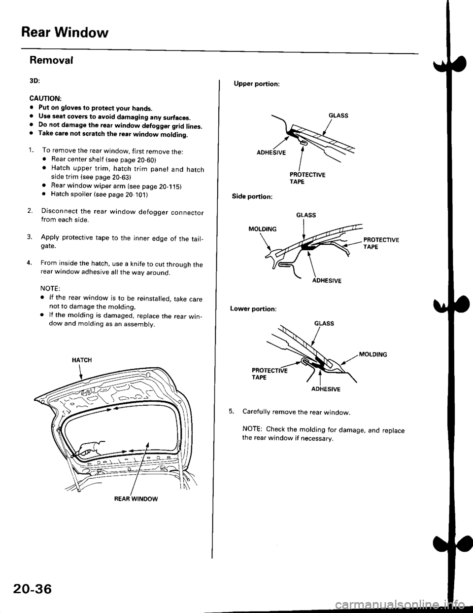
Rear Window
Removal
3D:
CAUTION:
. Put on gloves to ptotect your hands.. Us€ seat cove6 to avoid damaging any surfaces.. Do not damage the rear window defogger grid lines.. Take carg nol scratch the terr window molding.
'1. To remove the rear window, firsr remove the:. Rear center shelf (see page 20-60). Hatch upper trim, hatch trim panel and hatchside trim (see page 20-63)
2.
. Rear window wiper arm (see page 2O-115). Hatch spoiler (see page 20 101)
Disconnect the rear window defogger connectorfrom each side.
Apply protective tape to the inner edge of the tail_gate.
From inside the hatch, use a knife to cut through therear window adhesive all the way around.
NOTE:
. lf the rear window is to be reinstalled, take carenot to damage the molding.. lf the molding is damaged, replace the rear win_dow and molding as an assembly.
HATCH
ffi#
REAR WINOOW
20-36
Upper portioni
TAPE
Side portion:
Lower portion;
Carefully remove the rear window.
NOTE; Check the molding for damage, and replacethe rear window if necessary.
GLASS
ADHESIVE