1997 HONDA CIVIC Main bearing cap torque
[x] Cancel search: Main bearing cap torquePage 53 of 2189

Standards and Service Limits
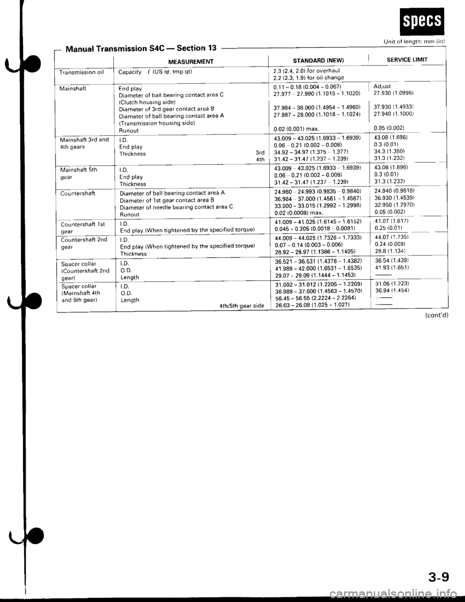
Manual Transmission S40 - Section 13
MEASUREMENT
Capacity | (US qt, tmp qt)
End playDiameter of ball bearing contact area A(Transmission housing side)Diameter of 4th, 5th gear contact area BDiameter of 3rd gear contact area CDiameter of ball bearing contact area D(Clutch housing side)Bunout
STANDARD INEW}'1.9 (2.0, 1.7)for overhaul1.8 (1.9, 1.6) for oitchange
0.11 0.18 (0.004 _ 0.007)21.987 - 22.000 (0.8656 0.8661)
26.980 26.993 (1.0622 _ 1.0627)33.984 34.000 (1.3380 1.3386)25.917 - 25.99011.0227 1.0232)
0.02 (0.001) max.
SEBVICE LIMIT
ro
MainshaftAdjust21.930 (0.8634)
26.930 ('1.0602i33.930 (1.3358)
25.92011.0205)
0.05 (0.002)
39.07 ('r.538)
0.33 {0.013)0.31 (0.012)
30.15 (1.187)
30.05 (1.183)
37.07 {1.459)0.31 (0.0'12)
28.35 (1.116)
LrO
39.009 39.025 (1.5358 1.5364)0.06 0.21 (0.002 0.008)0.06 0.19 (0.002 0.007)30.22 30.21 (1.190 1.192)30.12 - 30.17 (1.186 1.188)
37.009 37.025 (1.4570 _ 1.4577)0.06 - 0.19 (0.002 - 0.007)28.42 - 2a.47 11.119,1.1211Countershaft Diameter of needle bearing contact area ADjameter of lst gear contact area gDiameter of ball bearing contact area CRunout
30.000- 30.015 {1.181 1 - 1.1817)35.984 - 36.000 (1.4167 1.4173)24.980 24.993 (0.9835 - 0.9840)0.02 (0.001)max.
29.950 (1.1791)3s.930 r.4146)24.930 (0.9815)0.0s (0.002)
End play (When tightened by the specified torque)Thickness
41.009 - 41.025 ('�t.6145 1.6152)0.03 0.10 (0.001 _ 0.004)30.41 30.44 (1.197 - 1 198)
41 .01 11.617J0.22 (0.009)
30.36 (1.195)
gear End ptay (When tightened by the specified torque)44.009 - 44.025 (1.7326 1.7333)0.04 - 0.12 (0.002 - 0 005)31.91 31.96 (1.256 1.258)
44.01 11.t35)0.24 (0.009)
31.85 (1.2s4)
33.04 {1.301)38.93 (1.533)32.01 (1.260)
27.06 (1.065)
33.93 (1.336)
3r.93 {1.257)22.81 (0.898)
23.51 (0.926)
15.08 (0.594)
0.14 (0.006)
0.4 (0.016)
0.16 (0.006)
o.6210.0244112.78 (0.5031)
t.D.o. D.Length
33.000 - 33.010 (1.2992 1.2996)38.989 39.000 11.53s0_ 1.53s4)32.03 - 32.06 tl.261 - 1.2621Spacer collar(Mainshaft 4thand 5th gear)
Beverse rdler gear LD.Gear to reverse gear shaft cjearance
27.002 27.012 (1.0631 _ 1.0635)33.989 - 34.000 (1.3381 - 1.3386)3r.989 - 32.000 (1.2594 1.2598)22.83 - 22.86 (0.899 0.900)23.53 23.56 (0.926 - 0.928)
rs.016 15.043 (0.5912 _ 0.5922)0.032 0.077 (0.0013 _ 0.0030)Ring-to gear clearance {Ring pushed against gear)0.73 - 1.l8 (0 029 - 0.046)Fork finger thickness
Fork to-synchro sleeve clearance
lsv2nd/sth I 6.2 - 6.410.244 - O.ZS2)3rdl4th 7.4 i.6lO 2g1 O 2ggt0.35 - 0.65 (0.014 - 0.026)Beverse shitt fork Fork pawl groove widthFork to-reverse idler gear clearanceL groove widthFork'to-5th/reverse shift piece pin clearance
12.7 - 13.0 (0.50 _ 0.51)0.5 1. t (0.020 0.043)7 .05 - 7 .25 tO.21A - 0.28510.05 0.35 (0.002 0.014)Sh ift a rm A tnner diameter of sh ift arm C contact ffiShift arr14-go "L;L ".m C clearance13.05 13.13 (0.514 0.517)0.05 - 0.23 (0.002 _ 0.009)Inner diameter of shift arm B shaft contact pointShift arm 8-to shaft clearanceShift arm B to-shift piece clearanceDiameter of shift piece contact point
13.973 - 14.000 (0.5501 0.5512)0.013 0.070 (0.0005 _ 0.0028)0.2 - 0.5 {0.008 0.020)12.9 13.0 (0.508 - 0.512)MBS Shift prece Diameter of pin6.9 7 .1 \O.27 0 2A)
0.095 (0.004)
0.14 (0.006)
Adjust with shim
Differenlial carrier Pinion shaft bore diameterCarrier-to pinion shaft clearanceDriveshaft bore diameterCarrier to,driveshaft clearance
18.010 18.028 (0.7091 _ 0.7098)0.023 0.057 (0.0009 - 0.0022)26.025 26.04s {1.0246_ 1.0254)0.045 - 0.086 (0.0018 0.0034)BacklashPinion gear bore diameterPinion gear-to pinion shaft clearance
0.05 0.15 (0.002 0.006)18.042 - 18.066 (0.7103 _ 0.7113)0.055 - 0.095 {0.0021 _ o.oo37)
0 0.1 10 - 0.004)
3-8
LO
Page 54 of 2189

Unit of length: mm (in)
Transmission oil
43.009 43.025 (1.6933 - 1.6939)
0.06 0.21 (0.002 - 0.008)
31.42 - 31.41 \1.231 1.2391
t.D.End play
Thickness
Diameter of ball bearing contact area A
Diameter of lst gear contact area I
Diameter of needle bearing contact area C
Runout
LD.End play {When tightened by the specified torque)
Thickness
LD.o.D.Length
Spacer collar(CoLrntershaft 2ndgear)
Spacer collar(Mainshaft 4thand 5th gear)
LD.o.D.Lengtn
Manual TransmissionS4C - Section 13
M€ASUREMENT
MainshaftFnd plaVDiameter of ball bearing contact area C(Clutch housing side)Diameter of 3rd gear contact area B
Diameter of ball bearing contact area 'q(Transmission housing side)
Runout
Capacity | (US qt, lmp qt)
LD.End play
Thickness
2.3 (2.4,2.0) for overhaul2.2 (2.3, 1.9)for oil change
0.11 - 0.18 (0.004 - 0.007)21 .917 - 21 .990 11.1015 - 1 .10201
37.984 38.000 (1.4954 1.4960)
27.987 - 28.000 (1.1018 1.1024)
STANDARD {NEW)
0.02 (0.001)max.
SERVICE LIMIT
Adtust27.930 (1.0996)
37 930 (1.4933)
27.940 (1.1000)
0.05 (0.002)
Mainshaft 3rd and4th gears
43.009 - 43.025 (1.6933 1.6939)
0.06 - 0.21 (0.002 0.008)
34.92 - 34.91 \1.315 1.311)
31.42 - 31.41 (1.237 1.239)
24.980 24.993 (0.9835 0.9840)
36.984 37.000 (1.4561 - 1.4567)
33.000 - 33.015 (1.2992 - 1.2998)
0.02 (0.0008) max.
3rd4th
43.08 (1.696)
0.3 (0.01)
34.3 ('�t.350)
31.3 11.232)
43.08 (1.696)
0.3 (0.01)
31.311.232)
24.940 (0.9818)
36.930 (1.4539)
32.950 (1.2970)
0.05 (0.002)
41.07 (1.617)
0.25 (0.01)41.009 - 41.025 (1.6145 - 1.6152)
0.045 - 0.205 (0.0018 0.0081)
44.009 44.025 {1.7326 - 1.7333)
0.07 0.14 (0.003 - 0.006)28.92 - 28.97 (1.1386 -'�j.1405)
36.521 - 36.531 (1.4378 1.4382)
41.989- 42.000 (1.6531 - 1.6535)
29.07 - 29.09 11.1444 - 1.1453)
44.07 (1.735)
0.24 (0.009)
28.8 (1.134)
36.54 (1.439)
41.93 (1.651)
31 .0O2 - 31 .012 11 .2205 - 1 .2209'l
36.989 - 37.000 {1.4563 - 1.4570)
56.45 - 56.55 1'2.2224 - 2.2264126.03 - 26.0A 11 .025 - 1 .021 |
31.06 (1.223)
36.94 (1.454)
(cont'd)
3-9
Page 206 of 2189

Main Bearings
4.
Glearance
1.To check main bearing-to-journal oil clearance.
remove the main caps and bearing halves.
Clean each main journal and bearing half with a
clean shop towel.
Place one strip of plastigage across each main jour-
na l.
NOTE: lf the engine is still in the car when you bolt
the main cap down to check clearance, the weight
of the crankshaft and flvwheel will flaften the plasti-
gage further than just the torque on the cap bolt.
and give you an incorrect reading. For an accurate
reading, support the crank with a jack under the
counterweights and check only one bearing at a
time,
Reinstall the bearings and caps, then torque the
bolts.
lst step: 25 N'm (2.5 kgl'm. 18 lbf'ft)
FinalsteD:
B16A2 engine:
76 N.m (7.8 kgf.m, 56 lbf'ft)
D16Y5, Dl6Y7, D16Y8 engines:
51 N.m (5.2 kgf'm, 38 lbf'ft)
NOTE: Do not rotate the crankshaft during inspec-
tron.
Remove the cap and bearing again, and measure the
widest part ot the plastigage.
Main Boaring-toJournal Oil Clearance:
816A2 engine:
Standald {New}:
No. l, 2, 4, 5 Journals:
O.O2,l - 0.042 mm 10'00(B - 0.0017 in)
No. 3 Journals:
0.030 - 0.048 mm {0'0012 - 0'0019 in)
Servico Limit: 0.06 mm {0.002 in,
Dl6Y5, Dl6
r, Dl6Y8 engines:
Standard (Nsw):
No. 1,5 Journals:
0.018 - 0.035 mm {0.0007 - 0'001'[ in)
No. 2. 3, 4 Journals:
0.02,1 - 0.0,(2 mm {0'0009 - 0.0017 in}
Service Limit: 0.05 mm (0.002 in)
\
7-9
7.
lf the plastigage measures too wide or too narrow,
(remove the engine if it's still in the car), remove the
crankshaft, and remove the upper half of the bear-
ing. Install a new. complete bearing with the same
color code {select the color as shown on the next
page), and rechsck the clearance.
CAUTION: Do nol fil€, shim, or scrape the bearings
or tho cap3 to adiust cleatanc€.
lf the plastigage shows the clearance is still incor-
rect, try the next larger or smaller bearing (the color
listed above or below that one), and check again
NOTE: lf the proper clearance cannot be obtained
by using the appropriate larger or smaller bearings,
replace the crankshaft and start over.
Page 220 of 2189

PistonsGrankshaft
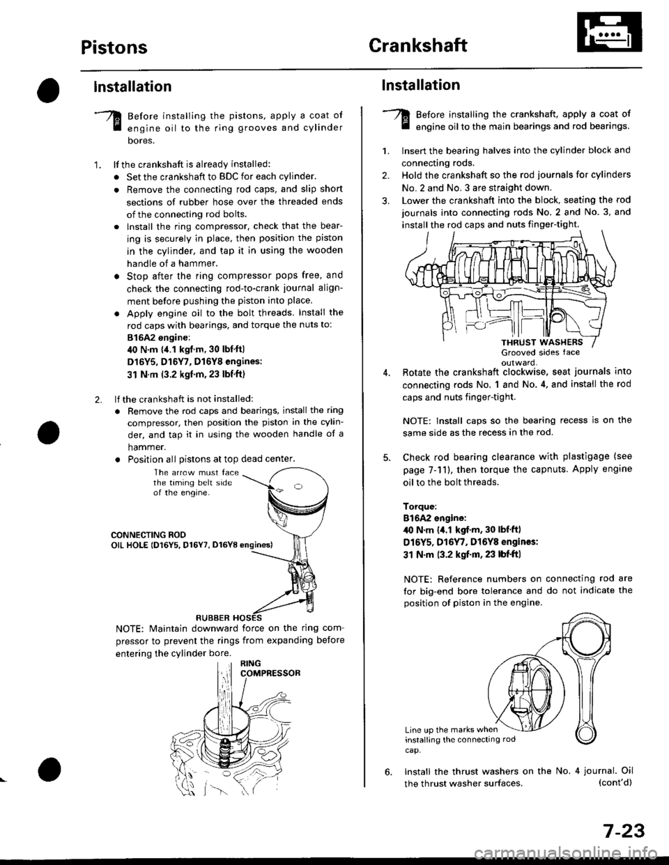
lnstallation
Before installing the pistons, apply a coat of
engine oil to the ring grooves and cylinder
bores.
lf the crankshaft is already installed:
. Set the crankshaft to BDC for each cylinder.
. Remove the connecting rod caps, and slip short
sections of rubber hose over the threaded ends
of the connecting rod bolts.
. lnstall the ring compressor. check that the bear-
ing is securely in place, then position the piston
in the cylinder, and tap it in using the wooden
handle of a hammer.
o Stop after the ring compressor pops free, and
check the connecting rod-to-crank journal align-
ment before pushing the piston into place
. Apply engine oil to the bolt threads. Install the
rod caps with bearings, and torque the nuts to:
815A2 engine:
40 N.m {,1.1 kgf.m, 30 lbf'ft|
D16Y5, D16Y7, D16Y8 engines:
31 N.m (3.2 kgf'm,23 lbf'ft)
lf the crankshaft is not installed:
. Remove the rod caps and bearings, install the ring
compressor, then position the piston in the cylin-
der, and tap it in using the wooden handle of a
hammer.
. Position all Distons at top dead center.
1.
2.
The arrcw must facethe taming belt sideof the engine.
CONNECTING ROOOIL HOLE lD16Y5, D16Y7, D16YB ongines)
NOTE: Maintain downward force on the ring com-
pressor to prevent the rings from expanding before
entering the cylinder bore.
RUBBER
,lll
lnstallation
Before installing the crankshaft, apply a coat of
engine oil to the main bearings and rod bearings.
Insert the bearing halves into the cylinder block and
connecting rods.
Hold the crankshaft so the rod journals for cylinders
No.2 and No. 3 are straight down.
Lower the crankshaft into the block, seating the rod
journals into connecting rods No. 2 and No. 3, and
install the rod caps and nuts finger-tight.
1.
2.
3.
5.
Grooved sides faceoulward.Botate the crankshaft clockwise, seat journals into
connecting rods No, 1 and No.4, and install the rod
caps and nuts finger-tight.
NOTE: Install caps so the bearing recess is on the
same side as the recess in the rod.
Check rod bearing clearance with plastigage (see
page 7-11), then torque the capnuts. Apply engine
oil to the bolt threads.
Torque:
816A2 sngine:/l{, N.m {a.l kgf.m, 30 lbf'ftl
D16Y5, D16Y7, Dl6Y8 engines:
31 N.m (3.2 kgf.m, 23 lbf'ft|
NOTE: Reference numbers on connecting rod are
for big-end bore tolerance and do not indicate the
position of piston in the engine.
Line up the marks wheninstalling the connectrng rod
cap.
6. Install the thrust washers on the No. 4 journal. Oil(cont'd)
7-23
the thrust washer surfaces,
Page 635 of 2189

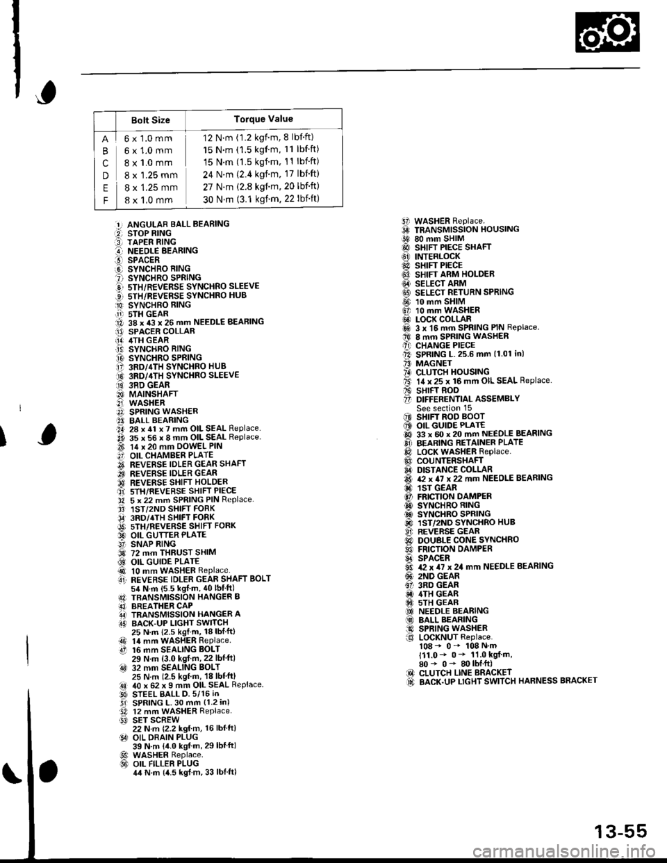
Bolt SizeTorque Value
cn
E
F
6x1.0mm
6x1.0mm
8 x 1.0 mm
8 x '1.25 mm
8 x 1.25 mm
8 x 1,0 mm
12 N.m (1.2 kgnm, 8 lbf'ft)
15 N.m (1.5 kgf'm, 11 lbf ft)
15 N.m (l.5 kgf.m, 11 lbift)
24 N'm (2.4 kgim, 17 lbift)
27 N.m (2.8 kgf.m,20 lbf'ft)
30 N.m (3.1 ksf m. 22 lbift)
5i WASHER Replace.6 TRANSMrssioN HouslNG!9 80 mm SHIM@ SHIFT PIECE SHAFT(6' INTERLOCK@ sHrFr PECE6} SHIFT ARM HOLDER@ seucr nnrvtI9 SELECT RETURN SPRING
@ 10 mm SHIM6, 10 mm WASHER@ LOCK COLLARi6sl 3 x l5 mm SPRING PIN Replace.t0 8 mm SPRING WASHERA) CHANGE PIECEll SPRING L.25.6 mm (1.01 in)'' MAGNET?4) CLUTCH HOUSINGta. 14 x 25 x 16 mm OIL SEAL Replace.A sHrFT BooO D|FFERENT|aL ASSEMBLYSee section 15iIO SHIFT ROD BOOT6 OIL GUIDE PLATE@ 33 x 60 x 20 mm NEEDLE BEASINGO BEARING RETAINER PLATElD LocK WASHER Replace..0 couNTERSHAFIA DISTANCE COLLAR6 & x 4I x 22 mm NEEDLE BEARING6. 1sr GEAR@ FRICTION DAMPERO SYNCHRO RING.d SYNCHRO SPRING@ 1ST/2ND SYNCHRO HUB..9i. REVERSE GEARC) DOUBLE CONE SYNCHROO FRICTION DAMPERS SPACER6 T2 x TI x 24 mm NEEDLE BEARING(!' 2ND GEAR61 3RD GEARiD 4TH GEAR@ 5TH GEAR(O NEEDLE BEARING(10 BALL BEARING@ SPRING WASHERf,o LoCKNUT Replace.108 - 0- 108 N'm111.0- 0* 11.0 kgf m,80* 0- 80lbI.ft)IO CLUTCH LINE BRACKET.d BACK.UP LTGHT SWITCH HARNESS BRACKET
:!, ANGULAR BALL BEABING:2, STOP RING:3] TAPER RING..-I NEEOLE BEARINGl!-- SPACERO SYNCHRO RING? SYNCHRO SPRINGE 5TH/REVERSE SYNCHRO SLEEVE...] sTH/REVERSE SYNCHRO HUB
O SYNCHBO EING.11-r sTH GEAR1A 38 x 43 x 26 mm NEEDLE BEARINGI13) SPACER COLLAR[!] /ITH GEAR.T5) SYNCHRO RING
O SYNCHRO SPRING17 3RD/4TH SYNCHRO HUB
O 3RD/4TH sYNcHRo SLEEVE
ii9 38D GEAR8I MAINSHAFT2i WASHERA SPRING WASH€R?I BALL BEARING.a4, 28 x 41 x 7 mm OIL SEAL Replace..2i 35 x 56 x 8 mm OIL SEAL Replace.t-t 14 x 20 mm DowEL PIN
.'] OIL CHAMBER PLATE
O REVERSE IDLER GEAR SHAFT.iI.., REVERSE IDLER GEAR'd REVERSE SHIFI HOLDERait srH/REVERSE sHIFT PIECE'34 5 x 22 mm SPRING PIN Replace.3' 1ST/2ND SHIFT FORK,34' 3RD/4TH SHIFT FORKi9t) srH/nevense sstrr ronx33 OIL GUTTER PLATE!' SNAP RING3d 72 mm THRUST SHIM
@ OIL GUIDE PLATE4t 10 mm WASHER Replaceti REVERSE TDLER GEAR SHAFT BoLT54 N.m {5.5 kgf m, 40lbIft)4N TBANSMISSION HANGER B43] BREATHER CAPA,J TRANSMISSION HANGER AIT' BACK-UP LIGHT SWITCH
I
25 N.m {2.5 kgl.m, 18lblftl14 mm WASHER RePlaceaO 14 mmtt 16 mm16 mm SEALING BOLT29 N.m (3.0 kgf m,22 lbf ft):4s) 32 mm SEALING BoLT25 N m 12.5 kgl m, 18 lbl'ft)40 x 62 x I mm OIL SEAL ReplaceSTEEL BALL D.5/15 iNSPRING L. 30 mm {1.2 in)12 mm WASHER Replace.SET SCREW22 N.m {2.2 kg{ m, 16 lbl ftlOIL DRAIN PLUG39 N.m {4.0 kgf m, 29lbtftlWASHER Replace.OIL FILLER PLUG4,t N.m {4.5 kgl m, 33 lblftl
.!rl00
@l
13-55