Page 520 of 2189
\J
Fuol Iniection Air {FlA) Contlol Valve T$ting
1. Start the engine.
2. Remove the vacuum hose from the fitting on the
intake air duct, and connect a vacuum gauge to the
nose.
NOTE: Engine coolant temperature must be below
149"F (65"C).
VACUUM PUMP/GAUGE,
0-30 in.Hg.A973X - 041 -XXXXX
Raise and lower the engine speed, and make sure
the vacuum gauge reading changes as the engine
speed changes.
lf vacuum reading does not change check these
rtems:
. The vacuum lines of FIA system for misrouting,
leakage, breakage and clogging.
. The FIA controt valve for cracks or damage
. The cooling system (see section 10).
Hold the engine at 3,OOO rpm with no load (in Park
or neutral) until the radiator fan comes on, th€n let
it idle and recheck.
lf vacuum reading changes check these items:
a The FIA control valve for cracks or damage.
. The cooling system (see section 10).
11-251
Page 1090 of 2189

lnspection and Adjustment
Pump Pressure Check
Check the fluid pressure as follows to determine
whether the trouble is in the pump or gearbox.
NOTE: First check the power steering fluid level andpump belt tension.
CAUTION: Disconnect the high pr$sure hos€ with care
so as not lo spill the power sieering tluid on tha frame
and other parts.
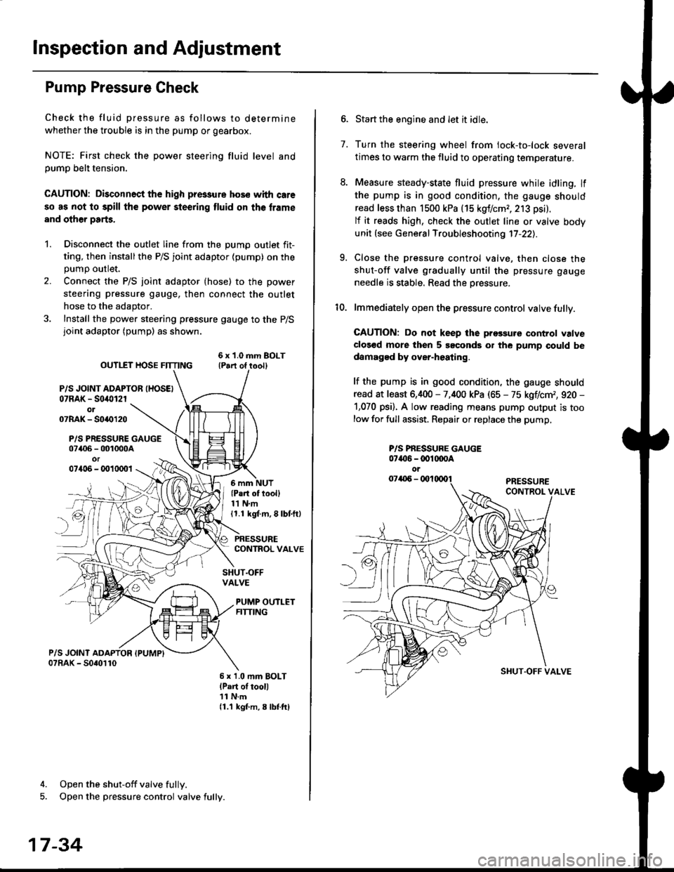
1. Disconnect the outlet line from the Dumo outlet fit-
ting, then installthe P/S joint adaptor (pump) on the
Dumo outlet.
2. Connect the P/S joint adaptor (hose) to the power
steering pressure gauge, then connect the outlet
hose to the adaptor.
3. Install the power steering pressure gauge to the P/Sjoint adaptor (pump) as shown.
ourlEr HosE FnrNo ,t"ll lrilu"ott
P/S JOINT ADAPTOB IHOSEI07RAK - S0i10l2rol07RAK- 50{{)120
P/S PRESSURE GAUGE07406 - 001000Aor07406 - 0010001
4. Open the shut-off valve fully.
5. Open the pressure control valve fully.
17-34
(Pa.t of tooll11 N.m11.1 kgt m, 8 lbf.ftl
PRESSURECONTROL VALVE
SHUT.OFFVALVE
PUMP OUTLETFITTING
6 x 1.0 mm BOLTlPart of tool)11 N.m11.1 kgf m, 8 lbtftl
7.
Start the engine and let it idle.
Turn the steering wheel from lock-to-lock several
times to warm the fluid to operating temperature.
Measure steady-state fluid pressure while idling. If
the pump is in good condition, the gauge should
read less than 1500 kPa (15 kgf/cmr, 213 psi).
lf it reads high, check the outlet line or valve body
unit (see General Troubleshooting 17-22).
Close the pressure control valve, then close the
shut-off valve gradually until the pressure gauge
needle is stable. Read the oressure.
lmmediately open the pressure control valve fully.
GAUTION: Do not keep lhe prossure control valve
clos€d more then 5 soconds or the pump could be
damagod by over-heating.
lf the pump is in good condition, the gauge should
read at least 6,400 - 7,400 kPa (65 - 75 kgflcm,, 920 -
1,070 psi). A low reading means pump output is too
low for full assist. Repair or replace the pump,
9.
P/S PBESSURE GAUGE07{16 -@1@OA
oi
SI{UT.OFF VALVE
Page 1980 of 2189

Gauges (cont'd)
- How the Gircuit Works
When the ignition switch is in ON (ll) or START (lll),
battery voltage is supplied through fuse 25 to the
gauges in the gauge assembly.
Speedometer and Odometer
The odometer and soeedometer drive circuits
receive pulses from the vehicle speed sensor
(VSS). The pulse rate increases as the car
accelerates. The frequency and duration of these
input pulses are measured and displayed by the
speedometer, odometer and tripmeter.
Tachometer
The tachometer drive circuit receives pulses from
the ignition control module (lCM) in the distributor
assembly or the ECM/PCM. The solid-state
lachometer then displays these pulses as engine
speed. For each 200 pulses per minute from the
ignition control modul€ (lCM) or the ECM/PCM, the
tachometer displays 100 RPM.
Engine Coolant Temperature Gauge
The engine coolant temperature gauge has two
intersecting coils wound around a permanent
magnet rotor. Voltage applied to the coils, through
fuse 25, generates a magnetic lield. The magnetic
field, controlled by the coolant temperature sending
unit, causes the rotor to rotate and the gauge
needle to move. As the resistance in the sending
unit varies, current through the gauge coils
changes. The gauge needle moves toward the coil
with the strongest magnetic field.
The 6ngine coolant temperature sending unit's
resistance varies from about 137 ohms at low
engine temperature to between 3H6 ohms at high
temperature (radiator fan running).
Refer to the Service Manual (Section 23, Electrical)
for specific tests or troubleshooting procedures.
81-2
(
Fuel Gauge (All except cX)
The fuel gauge has two intersecting coils wound
around a permanent magnet rotor. Voltage applied
to the coils, through tuse 25, generates a magnetic
field. The magnetic field, controlled by the fuel
gauge sending unit, causes the rotor to rotate and
the gauge needle to move. As the resislance in the
sending unit varies, current through the gauge coils
changes. The gauge needle moves toward the coil
with the strongest magnetic field.
The fuel gauge sending unit's resistance varies
from about 2-5 ohms at full, to about 110 ohms at
empty. When you turn the ignition switch off, the
gauge remains at the last reading until you turn the
ignition switch to ON (ll) or START (lll) again,
Refer to the Service Manual (Section 23, Electrical)
for specific tests or troubleshooting procedures.
Fuel Gauge (GX)
The fuel gauge has two intersecting coils wound
around a permanent magnet rotor. Voltage applied
to the coils, through fuse 25, generates a magnetic
field. The magnetic field, controlled by the PCM,
causes the rotor to rotate and the gauge needle to
move. The PCM calculates the gas quantity in the
fuel tank by using the fuel pressure value detected
by the tuel tank pressure sensor and the fuel
temperature value detected by the fuel tank
temperalure sensor, and outputs the signal to the
gauge assembly. The gauge needle moves toward
the coil with the strongest magnetic field.
When you turn the ignition switch off , the gauge
remains at the last reading until you turn the ignition
switch to ON (ll) or START (lll) again. When the
PCM detects a malfunction with the fuel pressure or
temperature, or detects a gas leak, the PCM
reduces the fuel meter to 0.
Refer to the Service Manual GX Supplement
(Section 11 , Fuel and Emissions) for specific tests
or troubleshooting procedures.
a
a