1997 HONDA CIVIC Shift cable
[x] Cancel search: Shift cablePage 45 of 2189

Towing
lf the vehicle needs to be towed, call a professional tow-
ing service. Never tow the vehicle behind another vehi
cle with iust a rope or chain lt is very dangerous'
Emergency Towing
There are three popular methods of towing a vehicle:
Flat-bed Equipment - The operator loads the vehicle on
the back of a truck. This is the best way of transporting the
vehicle.
Wheel Lift Equipment - The tow truck uses t\ivo pivoting
arms that go under the tires {front or rear} and lifts them
off the ground. The other two wheels remain on the
ground.
Sling-type Equipment - The tow truck uses metal cables
with hooks on the ends. These hooks go around parts of
the frame or suspension, and the cables lift that end of
the vehicle off the ground The vehicle's suspension and
body can be seriously damaged if this method of towing
is attemDted.
lf the vehicle cannot be transported by flat-bed. it should
be towed with the front wheels off the ground lf due to
damage, the vehicle must be towed with the front
wheels on the ground, do the following:
lvlanual Transmission and CW
. Release the parking brake
. Shift the transmission to neutral (CW to E position)'
Automatic Transmission
. Release the Parking brake.
. Sta rt the engine.
. Shift to LDll position, then E position.
. Turn oif the engine
CAUTION;
o lmploper towing preparation will damage ihe tfans-
mission. Follow the above procedute exaqtly lf you
cannot shift the tlansmission or start the engino
laulomatic transmissionl, yout vehicle must be trans-
ported on a flat-bed.
. lt is best to tow the vehicle no farther than 50 mil€s
(80 km), and ksop thE speed below 35 mph (55 km/hl
. Trying to lift 01 tow your vehicle by tho bump€F will
caus€ setious damagg. Ths bumpers are not dEigned
to supportthe vshicle's weigh.
tJO
1-43
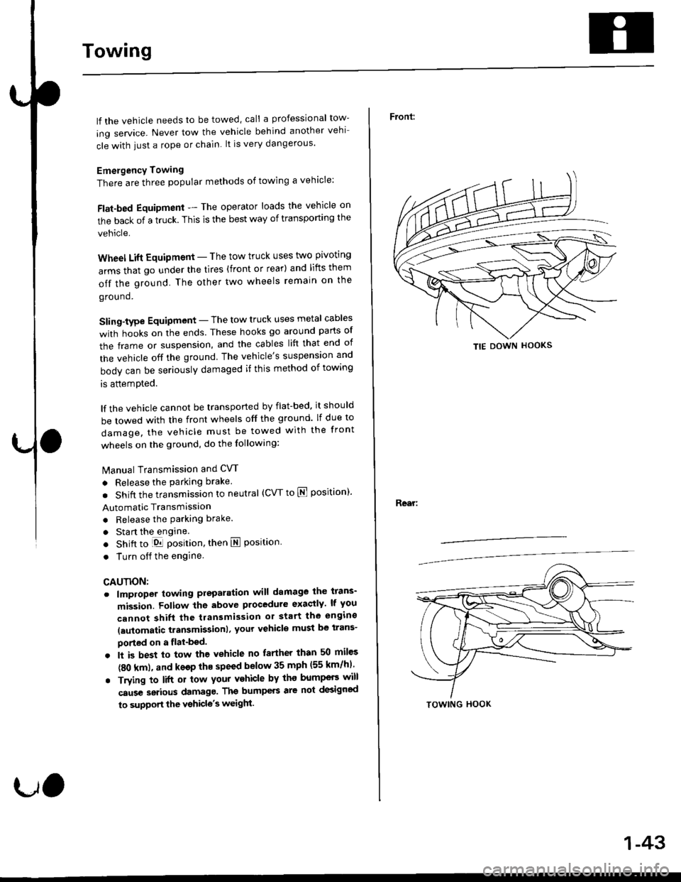
Front:
Rear:
TIE DOWN HOOKS
TOWING HOOK
Page 72 of 2189

ILubrication Points
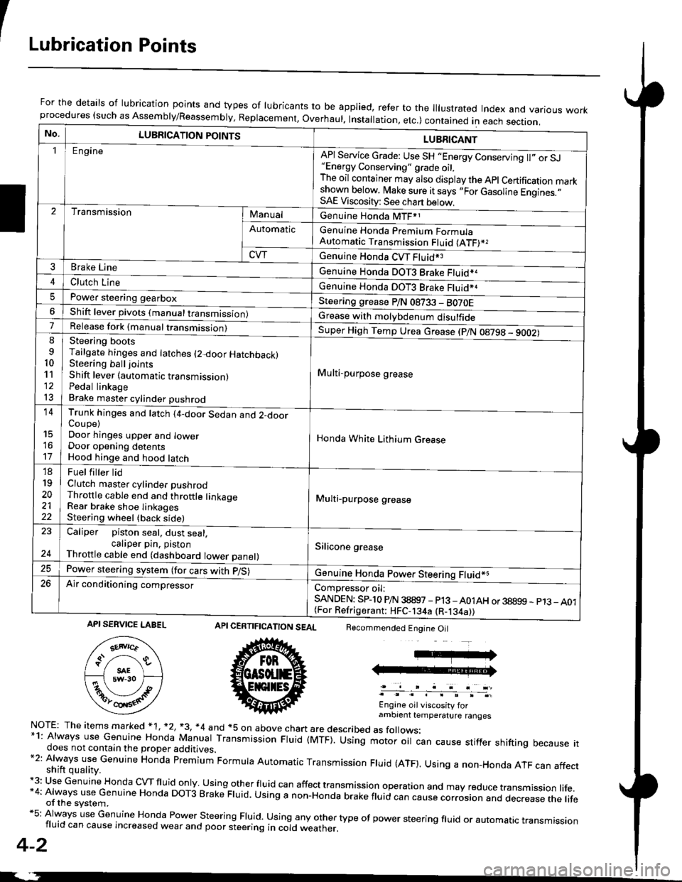
For the details of lubrication points and types of lubricants to be applied, refer to the lllustrated Index and various workprocedures (such as Assembly/Reassembly, Replacement, Overhaul. Installation, etc.) contained in each section.
No.LUBRICATION POINTS
Engine
LUBRICANT
"Energy Conserving" grade oil,The oil container may also display the Apl Certification markshown below. Make sure it says ,,For Gasoline Engines.,,SAE Viscosity: See chart below,
I
TransmissionManualGenuine Honda MTF*1
Genuine Honda Premium FormulaAutomatic Transmission Fluid (ATF)*,
Genuine Honda CVT Fluid*3
Genuine Honda DOT3 Brake Fluid*a
Automatic
CVT
3Brake Line
ClL,tci t""e4
I
Genuine Honda DOT3 Brake Fluid*aPower steering gearboxSteering grease P/N 08733 - BO70EShift lever pivots (manual transmission)Grease with molybdenum disulfide7-:ti
9
10'l'l
l3
14
't7
18
19
20
2122
Release fork (manual trancmi
Shift lever (automatic transmission)Pedal linkageBrake master cylinder pushrod
Super High Temp Urea crease (p/N 08798 - 9OO2)
i Multi-purpose grease
I
I
Honda White Lithium Grease
Multi-purpose grease
Silicone grease
@
Trunk hinges and latch (4-door Sedan and 2-doorCoupe)Door hinges upper and lowerDoor opening detentsHood hinge and hood latch-FUet T ter ttd
Clutch master cylinder pushrodThrottle cable end and throttle linkageRear brake shoe linkagesSteering wheel (back side)
23
E-
Caliper piston seal, dust seal,caliper pin. pistonThrottle cable end (dashboard lower panel)
Power steering system (for cars with p/S)
Air conditioning compressorComDressor oil:SANDEN: SPlo P/N 38897 - p13 -A01AH or 38899 - p13_ A01{For Refrigerant: HFC-134a (R-134a))
CERTIFICATION SEAL
ffi
NorE: The items m arked * 1, *2, +3, *4 and +5 on above chan are described as folows:*1: Always use Genuine Honda Manual Transmission Fluid (MTF). Using motor oil can cause stiffer shifting because itdoes not contain the proper additives.*2: Always use Genuine Honda premium Formula Automatic Transmission Fluid (ATF). Using a non-Honda ATF can affectshift quality.+3: Use Genuine Honda cVTfluid only usingotherfluid can affect tra nsmission operation and may reduce transmission life.*4: Always use Genuine Honda DoT3 Brake Fluid. Using a non-Honda brake fluid can cause corrosion and dec.ease the lifeof the svstem.*5: Always use Genuine Honda Power steering Fluid. using any other type of power steering fluid or automatrc transmissionfluid can cause increased wear and poor steering in cold weather.
4-2
Recommended Engine Oil
Engine oil viscosity forambrent temperature ranges
API SERVICE LABEL
Page 101 of 2189

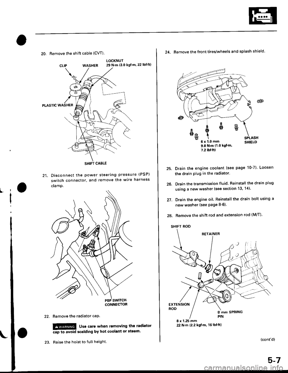
20. Remove the shift cable (CVT)
WASHER
Pt-Aslc
21. Disconnect the Power
switch connector, and
cramp.
LOCKNUT29 N.m {3.0 kgf m,22lbf'ft}
steering pressure (PSP)
remove the wire harness
CLIP
ll
I
Remove the radiator caP.
!!!@ usa care when l€moving the tadiator
Ap to avoid scalding by hot coolant or steam'
Raise the hoist to full height.
SHIFT CABLE
(cont'd)
25.
26.
27.
24. Remove the front tires/wheels and splash shield.
u x l.u mm SHIELD9.8Nm(1 0 kqt'm,
7.2lbf.ftl
Drain the engine coolant (see page 10-7). Loosen
the drain plug in the radiator.
Drain the transmission fluid Reinstall thedrainplug
using a new washer (see section 13, 14).
Drain the engine oil. Reinstall the drain bolt using a
new washer (see page 8-6).
28. Remove the shift rod and extension rod (M/T)
SHIFT ROD
EXTENSIONROD
8 x 1.25 mm22 N.m t2.2 kgf'm, 't6lbtft)
ER
6x1.0mm
Page 102 of 2189

Engine Removal/lnstallation
Removal(cont'dl
29. Remove the Ay'C compressor.
NOTE: Do not disconnect the Ay'C hoses.
30.
8x 1.25 mm A/C COMPRESSOR24 N.m (2.{ kgf.m, t7 tbtft}
Remove the shift cable (IVT).
NOTE:
. Take care not to bend the cable when removingit. Always replace any kinked cable with a newone.
. Adjust the shift cable when installing (see sec_tion 14).
8 x 1.25 mm22 N.m (2.2 kgf.m, 16 lbf.frl
LOCK WASHERBeplace.6x1.0mm14 N.m (1.4 kgf.m, tO tbtft)
5-8
A/C COMPRESSOR
t
{
31. Remove exhaust pipe A.
Dl6Y5. D16Y7 engines:
8 x 1.25 mm22 N.m 12.2 ksl.m. 16 tbI.fr)Replace.
SELF.LOCKING8 x 1.25 mm16 N.m (1.6 kgtm,12 tbt.ftlReplace.
D16Y8 ongin6;
8 x 1.25 mm22 N.m (2.2 kgf.m. 16 tbf.ftlReplace.
GASKETReplace.
SELF.LOCKING NUT10 x 1.25 mm33 N.m {3.4 kgt.m,25 lbr'frlReplace.
SELF.LOCKING NUT8 x 1.25 mm16 N.m 11.6 kgf.m, 12 lbtft)Replace.
SELF-LOCKING NUTl0 x 1.25 mm54 N.m (5.5 kgf.m, 40 lbf.ft)Replace.
Page 110 of 2189

Engine Removal/lnstallation
Installation (cont'd)
Except CVT:
12 x 1.25 mm64 N.m (6.5 kgd.m,
Tighten the bolts/nut on the left front mount in thenumbered sequence shown {O - @).
(t 12 x 1.25 mm83 N'm (8.5 kgf.m,61 tbt.trl
/+4 N.m 14.5 kgf.m,33 lbt.trl
O 12 r 1.25 mm59 N.m 16.0 kgt.m,43 tbt.rtlSeplace.
5-16
\
7. Perform the following:
. Clean the areas where the driveshaft(s) and theintermediate shaft contact the transmission (dif_ferential) thoroughly with solvent or carburetorcteaner, and dry with compressed air.. Check that the set rings on the ends of the drive_shaft and intermediate shaft click into place.CAUTION: Use new set rings,. Adjust the shift cable (see section 14).. Adjust the throttle cable (see section 11).. Adjust the cruise control cable (see section 23).. Refill the engine with engine oil (see page 8-6).. Refill the transmission with fluid (see section 13,14).
. Refill the radiator with engine coolant (see page10-7).
. Bleed air from the cooling system with the heatervalve open (see page j0-7).
. Clean the battery posts and cable terminals withsandpaper, assemble them, then apply grease toprevent corrosaon.. Inspect for fuel leakage (see section j l).After assembling the fuel line, turn on l) the igni_tion switch (do not operate the starter) so that thefuel pump runs for approximately two secondsand the fuel line pressurizes. Repeat this opera_taon two or three times, then check for fuel leak_age at any point in the fuel line,
Page 589 of 2189

. Torque the mounting bolt and nuts in the sequence
shown.
O 12 x 1.25 mm64 N.m {6.5 kgt.m,47 lbf.fr)
@ 12 x 1.25 mm74 N.m (7.5 kgl'm,54 tbt.fr)
Check that the bushings are not twisted or offset.
Install the clip as shown.
SHIFT ROD
Turn the boot so the hole is facing down.
Make sure the boot is installed on the shift rod.
O) 12 x 'l.25 mm64 N.m 16.5 kgl.m,47 tbt.ft)
I
a
a
a
a
8 x 1.25 mmN.m t2.2 kgt.m, l6 lbl'tt)
6 x 1.0 mm9.8 N.m (1.0 kgl.m.7.2 tbf.tr)
. Apply grease to the slave cylinder push rod.
NOTE: Use only Super High Temp Urea Grease
{P/N 08798 - 9002}.
CLUTCHUNE
a
a
(P/N-6tl
08798-9002)
8 x 1.25 mm22 N.m 12.2 kgl.n.16 tbf.frl
. Turn the breather cap so that the "F" mark points at
the front of the car as shown.
Refill the transmission with the recommended oil
(see page 13-3).
Connect the positive (+) cable first, then the negative
(-) cable to the battery.
Check the clutch oDeration,
Shift the transmission and check for smooth opera-
tion.
Check the front wheel alignment (see section 18).
FRONT
13-9
Page 632 of 2189

Transmission Assembly
lnstallation
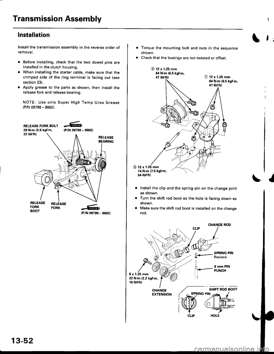
Install the transmission assembly in the reverse order of
removal.
. Before installing, check that the two dowel pins are
installed in the clutch housing.
. When installing the starter cable. make sure that the
crimped side of the ring terminal is facing out (see
section 23).
. Apply grease to the parts as shown, then install the
release fork and release bearing.
NOTE; Use only Super High Temp Urea Grease(P/N 08798 -9002).
RELEASE FORK BOLT29 N.m 13.0 kgf.m,22 tbllrl
(P/N 08798 - 9rD2l
-R1
tP/N 08798 -
13-52
CLIP
L f ;
Torque the mounting bolt and nuts in the sequence
shown.
Check that the busings are not twisted or offset.
@ t2 x 1.25 mm6,t N.m 16.5 kgtm,47 lbf.ft)O t2 x 1.25 mm6,r N.m (6.s kg{.m,17 tbf.ft)
O 12 x 1.25 mm7ilNm17.5kgf.m,5it lbt ft)
I
Install the alip and the spring pin on the change joint
as snown.
Turn the shift rod boot so the hole is facing down as
snown.
Make sure the shift rod boot is installed on the changerod.
CHANGE ROO
FL.- SPRING PINll heptace,
8 mm PINPUNCH
/ "*,*
lo,iD(
CHANGE ./EXTENSfoN ( ^ st
l?rffi
l\K
Page 633 of 2189

. Apply grease to the slave cylinder push rod.
NOTE: Use only Super High Temp Urea Grease
(P/N 08798 - 9002).
6x1.0mm9.8 N'm (1.0 kgl m,
7.2 tbl.ft)
-6,4- 9m2)
Refillthe transmission with oil (see page 13-47).
Connect the positive (+) cable first, then the negative
( - ) cable to the battery.
Check the clutch oPeration.
Shift the transmission, and check for smooth opera-
tion.
Check the front wheel alignment (see section 181.
(P/N 08798
8 x 1 .25 mm22N.n 12.2 kgl'm,16 tbf.ftl
a
a
a
a