Page 47 of 2189

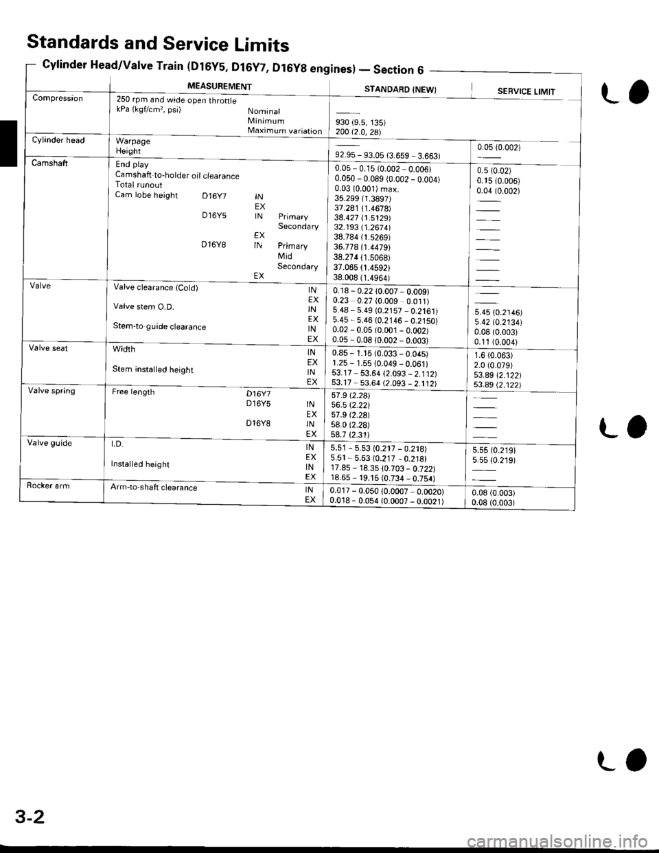
(urbY5, ul6Y7, Dl6Yg enl
MEASUREMENT
Sines) -Section6 -
STANDARD INFWTCompression250 rpm and wide open throftlekPa {kgf/cm,, psi) NominalMinimumMaximum variationWarpageHeight
End play
Camshaft to-holder oil clearanceTotal runoutCam lobe height D16y7
D16Y5
D16Y8
INEXIN
EXIN
EX
Secondary
PrimaryMidSecondary
930 {9.5, 135)200 12 0 ?R\Cylinder head
92.95 - 93.05 {3.659 3.663)0.05 {0.002)
Camshaft0.05,0.15 (0.002 0.006)0.050 - 0.089 (0.002 _ o.oo4)0.03 (0.001)max.
35.299 (1.3897131.241 /.1.4678)38.427 (1.5129)32.193 11 .267 4l38.784 (1.5269)
36.778 (1.4479)
38.274 (1.5068)
37.065 .4592)38.008 (1.4964)
0.5 (0.02)
0.15 (0.006)
0.04 (0.002)
=
Valve clearanca {Cold)
Valve stem O.D.
Stem-to guide clearance
width
Stem insta ed height
Free lengrh Dt6y7D16Y5
INEXINEXINEX
INEXINEX
INEXINEX
INEXINEX
D16Y8
t.D.
Installed height
0.18 - 0.22 10.007 - 0.009)0.23 0.27 (0.009 0.011)5.48 - 5.49 (0.2157 0.2161)5.45 - 5.46 {0.2146 _ 0.2150}0.02 - 0.05 (0.001 _ o.oo2)0.05-008lono2-nnn?l
5.45 (0.2146)
5.42 tO.213410.08 (0.003)
0.11 (0.004)
1.6 (0.063)
2.0 (0.079)
53.a9 \2.122|j$.a9 Q.122)
Valve seat0.85 - 1.15 (0.033 - 0.045)1.25 - 1.55 10.049 - 0.061i53.17 - 53.64 {2.093 _ 2.112)53.17 - 53.64 (2.093 _ 2.112)Valve spring57 .9 (2.2a)
56.5 \2.22157 .9 t2.29l58.0 (2.2a)
58.7 {2.31iValve guide5.51 - 5.53 (0.217 - 0.218)5.51 - 5.53 (0.217 _ 0.218)17.85 - 18.35 \0.103 - 0.722)18.65 19. t5 (0.734 _ 0.754)
5.55 t0.219)5.5s {0.219)
Rocker armArm-to shaft clearanceINEX0.017 - 0.050 (0.0007 0.0020)0.018 - 0.054 (0.0007 - 0.0021)0.08 (0.003)
0.08 (0.003)
Standards and Service Limits
Cylinder Head/Valve Train (Dt6y5, Dt6y7, D
L,
ra
3-2
LO
Page 48 of 2189

Unit of iength: mm (!n)
930 (9.5, 135)20012.0,zal
0.05 - 0.15 (0.002 - 0.006)
0.050 - 0.089 (0.002 - 0.004)
0.0310.001)max.33.088 (1.3027i
36.261 {1.4278)34.978 (1.3771)
32.785 {1.2907)35.720 (1.4063)
34.691 (1.3658)
u*u lo.r,ool5.420 (0.2134)
0.08 (0.003)
0.11 (0.004)
2.0 (0.08)
2.0 (0.08)
38.185 (1.5033)
37.885 (1.4915)
250 rpm (min riand Nominal
wide open throttle Minimum
kPa (kqf/cm'�, psi) Maximum variation
End play
Camshaft-to holder oil clea€nce
Total runoutCam lobe height lN PrimaryMidSecondaryEX PrimaryMidSecondary
0.15 - 0.19 (0.006 - 0.007)*
0.17 - 0.21 (0.007 - 0.008)*
5.475 - 5.485 10.2156 - 0.2159)
5.450 - 5.460 (0.2146 - 0.2150)
0.025 - 0.055 (0.0010 0.0022)
0.050-0.080 (0.0020 - 0.0031)
Valve clearance
Valve stem O.D.
Stem-to-guide clearance
INEXINEXINEX
1.25 - 1.55 {0.049 - 0.061)r.25 - 1.55 (0.049 - 0.061)
37.465 - 37.935 (1.4750 - 1.4935)
37.165 - 37.635 (1.4632 - 1.4817)
INEXINEX
width
Stem installed height
40.92 (1.611)*'
40.91 (1.6111"
36.71 (1.415)
41.96 (1.652)*r
4 r.94 (1.651)*'
free t*gth lN OUTER
5.51 - 5.53 (0.217 - 0.218)5.51 - 5.53 (0.217 - 0.218i12.55 - 13.05 (0.494 0.5'�j4)
12.55 - 13.05 (0.494 - 0.514)
LD. lNEX
Installed height lNEX
0.025 - 0.052 (0.0010 0.0020)
o.o2s - 0.052 {0.0010 0.0020)
Cylinder Head/Valve Train(816A2 engine) - Section
MEASUREMENTSTANDARD INEW)SERVICE LIMIT
*: Measuring point between camshaft and rocker arm'*1: NTHON H;TSUJO manufactured vatve spring. *2: CHUO HATSUJO manutactured valve spnng.
3-3
Page 125 of 2189

Valve Seals
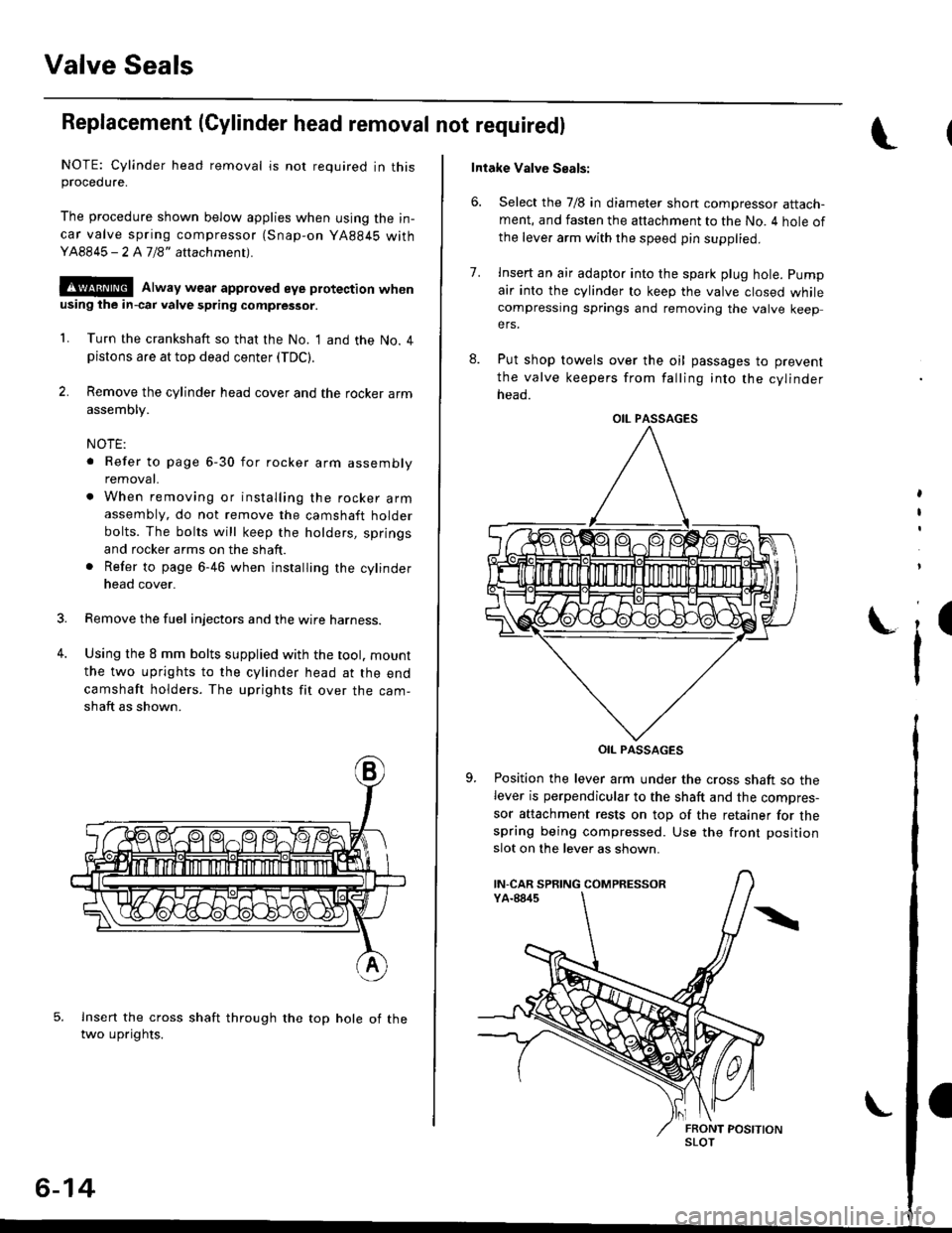
Replacement (Cylinder head removal not requiredl
NOTE: Cylinder head removal is not required in thisprocedure.
The procedure shown below applies when using the in-
car valve spring compressor (Snap-on YA884S withY48845 - 2 A7/8" attachment).
!@@ Alway wear approved eye protection whenusing ihe in-cai valve spring compressor.
1. Turn the crankshaft so that the No. I and the No. 4pistons are at top dead center (TDC).
2. Remove the cylinder head cover and the rocker arm
assembly.
NOTE:
. Refer to page 6-30 for rocker arm assembly
removat.
. When removing or installing the rocker armassembly, do not remove the camshaft holder
bolts. The bolts will keep the holders, springs
and rocker arms on the shaft.
. Refer to page 6-46 when installing the cylinder
head cover.
Remove the fuel injectors and the wire harness.
Using the 8 mm bolts supplied with the tool. mount
the two uprights to the cylinder head at the end
camshaft holders. The uprights fit over the cam-
shaft as shown.
lnsert the cross shaft through the top hole of thetwo uprights.
3.
4.
6-14
Intake Valve Seals:
6. Select the 7/8 in diameter short compressor attach-ment, and fasten the attachment to the No. 4 hole of
the leve. arm with the speed pin supplied.
8.
7.lnsert an air adapto. into the spark plug hole. pump
air into the cylinder to keep the valve closed whilecompressing springs and removing the valve keepers.
Put shop towels over the oil passages to prevent
the valve keepers from falling into the cylinder
neao.
OIL PASSAGES
Position the lever arm under the cross shaft so thelever is perpendicular to the shaft and the compres-
sor attachment rests on top of the retainer for thespring being compressed. Use the front position
slot on the lever as shown.
,
I
i'
OIL PASSAGES
IN-CAR SPRING COMPRESSOR
SLOT
Page 137 of 2189

Cylinder Head
lllustrated Index (cont'dl
VALVE KEEPERS
SPRING RETAINER
INTAKE VALVE
VTEC SOLENOIDVALVE FILTEBReplace.
OIL CONTROLORIFICEClean.
INTAKE VALVE SEALReplace.VALVE SPRINGSEAT
INTAKE VAI.VEGUIOE
CAMSHAFTPULLEY
I
I
VALVE KEEPERS
SPRING RET
EXHAUST VALVESPRING
@
EXHAUST VALVESEALReplace.
8 x 1.25 mm37 N.m 13.8 kgt m,27 tbfitlApply engine oiltothe threads.
EXHAUSTVALVE
-vp
e,.io"o reassembring, crean at the parts in sorvent, dry them and appry rubricant to any contact parts.
D16Y8 engine:
LOST MOTIONASSEMgLY
ROCKER ARMASSEMBLYRemoval, page 6 30Inspection, page 6-34
5xl.0mm12 N.m {1.28.7 tbf.ft)
VALVE SPRINGSEATEXHAUSTVALVE O.RINGGUIDE Replace.Inspection, page 6 39Replacement, page 6 41Reaming, page 6 43
LOST MOTIONASSEMBLYHOLDER
INTAKE VALVEBemoval, page 6 38Installation, page 6 43
20 N.m 12.0 kgl.m, 14 tbf.ft)Apply engine oit to thethreads.
\
\
s9illl
CAMSHAFTInspection, page 6-36
OIL SEALBeplace.
CYLINDER HEADRemoval, page 6 27Warpage, page 6-40Valve seat reconditioning,page 6 40Installation, page 6-45
6x1.0mm12 N.m (1.2 kgt.m,8.7 lbf.ftlApply engine oil to thethreads,
Page 141 of 2189

Cylinder HeadRocker Arms
18.
19.
21.
22.
Removal (cont'd)
Remove the timing belt {see page 6-19).
Remove the camshaft pulley and back cover,
CAMSHAFTPULLEYClean when installing.
6x1.0mm8 x 1.25 mm37 N.m (3.8 kgf.m,21 tbtlrlApply engine oilto thebolt threads.
Remove the exhaust manifold {see pages 9-6 and 9_7).
Remove the intake manifold (see pages 9-2 thru 4).
Remove the cylinder head bolts, then remove thecylinder head.
CAUTION: To pr€vent warpage, unsclew lhe bohsin sequonce 1/3 turn at a time; rgpeat tho sequenceuntil all bolts are loosened.
CYLINDER HEAD BOLTS LOOSENING SEOUENGE:
6-30
Removal
1. Loosen the adjusting screws.
2. Unscrew the camshaft holder bolts, then,removethe rocker arm assembly.
NOTE:
a Unscrew the camshaft holder bolts two turns at at,me, in a crisscross pattern, to prevent damao_ing the valves or rocker arm assembly.. When removing the rocker arm assembly, do notremove the camshaft holder bolts. The bolts willkeep the camshaft holders, the springs and therocker arms on the shaft.
CAMSHAFT HOLDER BOLTS LOOSENINGSEOUENCE:
\(
ADJUSTING SCREWS
Page 142 of 2189
Disassembly/Reassembly
NOTE:
. ldentify parts as they are removed to ensure reinstallation in original locations'
. lnsDect rocker shafts and rocker arms (see page 6-35).
. Rocker arms must be installed in the same position if reused.
. when removing orinstallingthe rocker arm assembly,donot remove the camshaft holder bolts. The boltswill keepthe
holders, springs and rocker arms on the shaft.
-Zl prio, ,o reassemblinq, clean all the pans in solvent, dry them and apply lubricant to any contact points.
| - TNTAKE RocKER TNTAKE RocKER
D16Y7 engine:
Lefter "8" is stampedon rocker arm.
ARM A(4 placeslARM B
14 places)
INTAXE
ROCKER SHAFTSPRING{4 places)
ROCKER SHAFTCOLLAR14 plac.3l
ROCKER
I
II
I
BA\'A
fift L$\ft
:oo)[*o:
llll.I Jol----tNo.3 CAMSHAFT | | ruo. z cltusxerr 1i
T-* l=Bl-* d
,", 'l l=^ ^l
qJ?[l'-qJ'Ll
'I^ B A
EI
[ilHl"\9
t(cont'd)
6-31
Page 143 of 2189
Rocker Arms
Disassembly/Reassembly (cont'dl
NOTE:
. ldentify pans as they are removed to ensure reinstallation in original locations.. Inspect rocker shafts and rocker arms (see page 6-34).. Rocker arms must be installed in the same position if reused.t when removing or installing the rockerarm assembly, do not remove the camshaft holder bolts. The boltswill keeptheholders, springs and rocker arms on the shaft.
I erior to reassembring, crean a
the parts in sorvent, dry them and appry rubricant to any contact points.
D16Y5 engine:
ROCKER ARMS
TIMING PLATERUBBER BANO
(\
-]-
-P'g,rpt+.t't ll
\--,?|, -\2i lNo.5 CAMSHAFT _ lHOLDER l
No. 4 CAMSHAFTHOLDERNo. 3 CAMSHAFIHOLDERNo.2HOLDER
ra
I
EXHAUST ROCKERARM B{,1 plac€s)
EXHAUST ROCKEE SHAFT
Letter "A" is slamped
II{TAKE ROCKER SHAFT
!-r I
?h'ffi*ffi'
/^ ---IOCKER SHAFT
Letter "8" is stamped
6-32
Page 144 of 2189
D16Y8 engine:
No. 5 CAMSHAFTHOLDER
ARM B
ROCKER ARMS
No. 4 CAMSHAFTHOLOER
No. 3 CAMSHAFTHOLDER
No. 2 CAMSHAFTHOLDER
No. 'l CAMSHAFTHOLDER
R(rcKER SHAFTSPRING
Letter "B" is stampedLetter "A" is stamped
L
INTAKE SOCKER SHAFT
ROCKER SI{AFT
COLLARNUBBER BANDCOLLAR
EXHAUST ROCKER SHAFT
6-33