Page 1875 of 2189

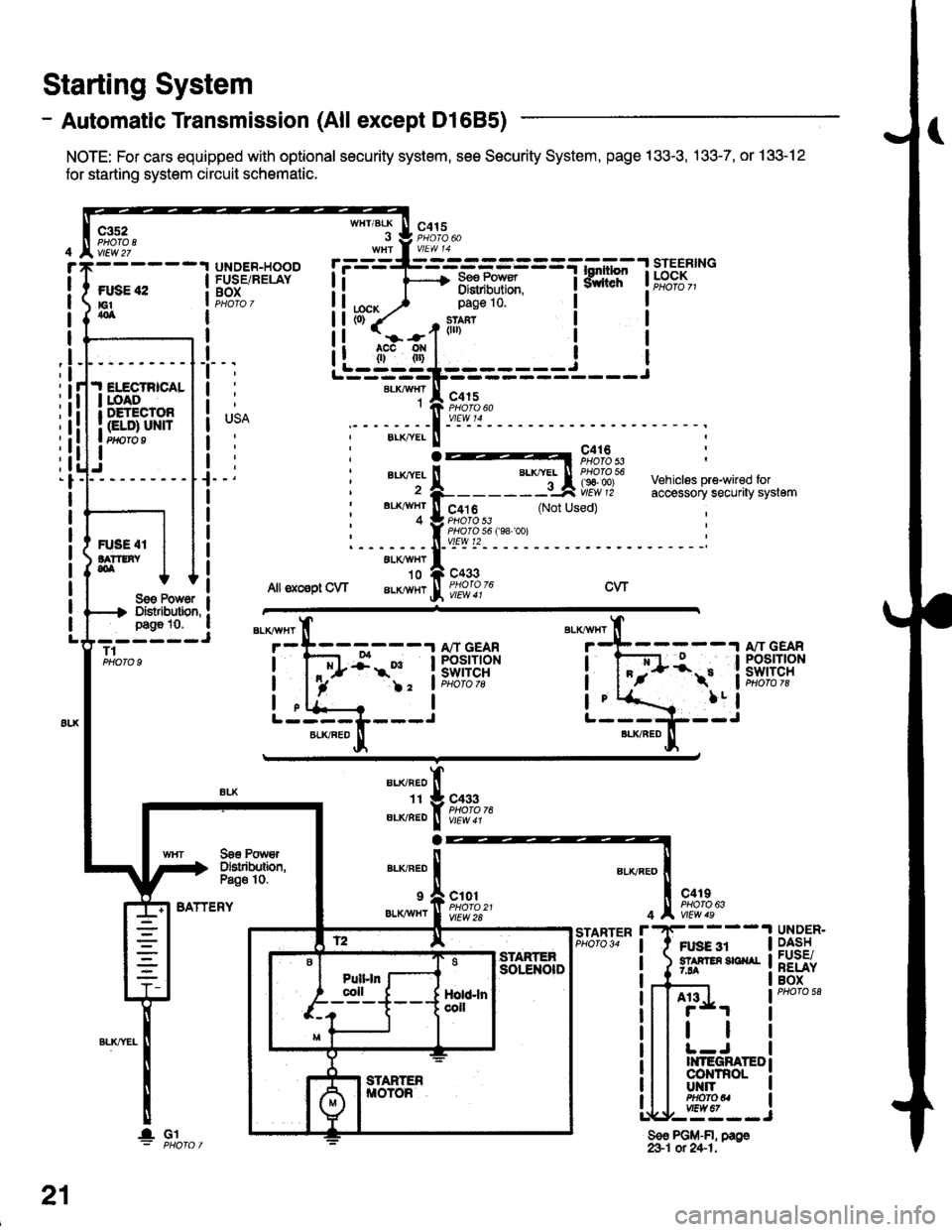
- Automatic Transmission (All except Dl685)
NOTE: For cars equipped with optional security system, see Security System, page 133-3, .133-7, or 133-12
for starting system circuit schomatic.
Starting System
c3s2PHO|O IvlEw 27
ftxiE "2E1404
WHT/BLK
I
lta":
c415
=-mF,Uf.
--l
9,lLT i ld;f,,"-
I
I
It
I
I
I
I
I
I
I
I
pag€ 10.
slan?(ll)
c415
I
Ji.I ELECTRICALI roAoI DETECTOR
I Gt ol ulra Ptfifo I
IJ
BLKAIVHT1
ELK./YEL
au(|vEL
BL'(4I/HT
4
c416PHOTO 53
c4t 6PHO|O 53PHO|O 56 f98 '�oo)vtEw t2
c433
Vehiclss pre-wired foraccessory securaty system(Not Used)
R'SE 4IlA??tNY,olALXAVHY'10
Allsxcsptow aLKlvHrcwSoe Pow6r IDistibution, !page 10. a- ----JT1PHOTO 9
BATTERY
BLKAVHT
7
L-----L---JBLKFED
13:;-1ifl;ft?R
!-
)2 'lPHoto tg
a
BLI(RED
1I
ELIVBED
ALKNED
c433PHOTO 76
Soe PowrDslributbn,Pa€o 10.
9 a c101
er.xiwxr I ffo,rtfl'�t
c4rIPHO|O 63
Ft gg 3r5? F En 3E ^r7.94
4
r'STARTERPHO|O 34UNDER.DASHFUSE/RELAYBOX
A13
tl
II{TEGRATEDco|{TnoLUT{ITPHOfOUvtEw 67,--==--J
Sso PGM-FI, page&1 ot 24-1.
21
lGl
Page 1876 of 2189
- Automatic Transmission (D1685)
c352
vtEw27
FUSE 42tGtao
.I ELECTRICALI LOADr DETECIOn
| (ELD) uNtrI PHOTO 9
I
UNDER.HOOOFUSE/RELAYBOX
r=-----L-_-_-_-_-_-=_-_-Tl.*1"","1#"Ei]""
li F 3,"j,[',ul
WHT/BLK
. J 9,1'3.WHt a V|EW 14
tcx,^ ) Page 10'
PHOTO 76
1--*---''!N"t- \o3bz7
See PowerDistribution,page 10.
c433
ALKRED4
r-^==.1
Stadorcontrol
POWERTRAINCONTROLMODULE (PCM)
c101
vtEw 28
ll
"'{----1iLi.' | |
Li-gl{l======i---i
"i*-iIr-m'
:il
See PowerDistribdion,Page '10.
".u,"if---'
-,*! s#;:{"
BLKAVHT N V/EW a t
STARTERCUTFELAYPHO|O 129
(99100)
A"/T GEARPOStTtONswrTcH
See PGlr-Fl,page 25.
STARTER
c419
FUSE 31STAffER Src{AI7.54
UNDER-DASHFUSE/NELAYBOX
BLKREO
11
"'-";;tr
A't 3
BATTERY
21-1
Page 1877 of 2189

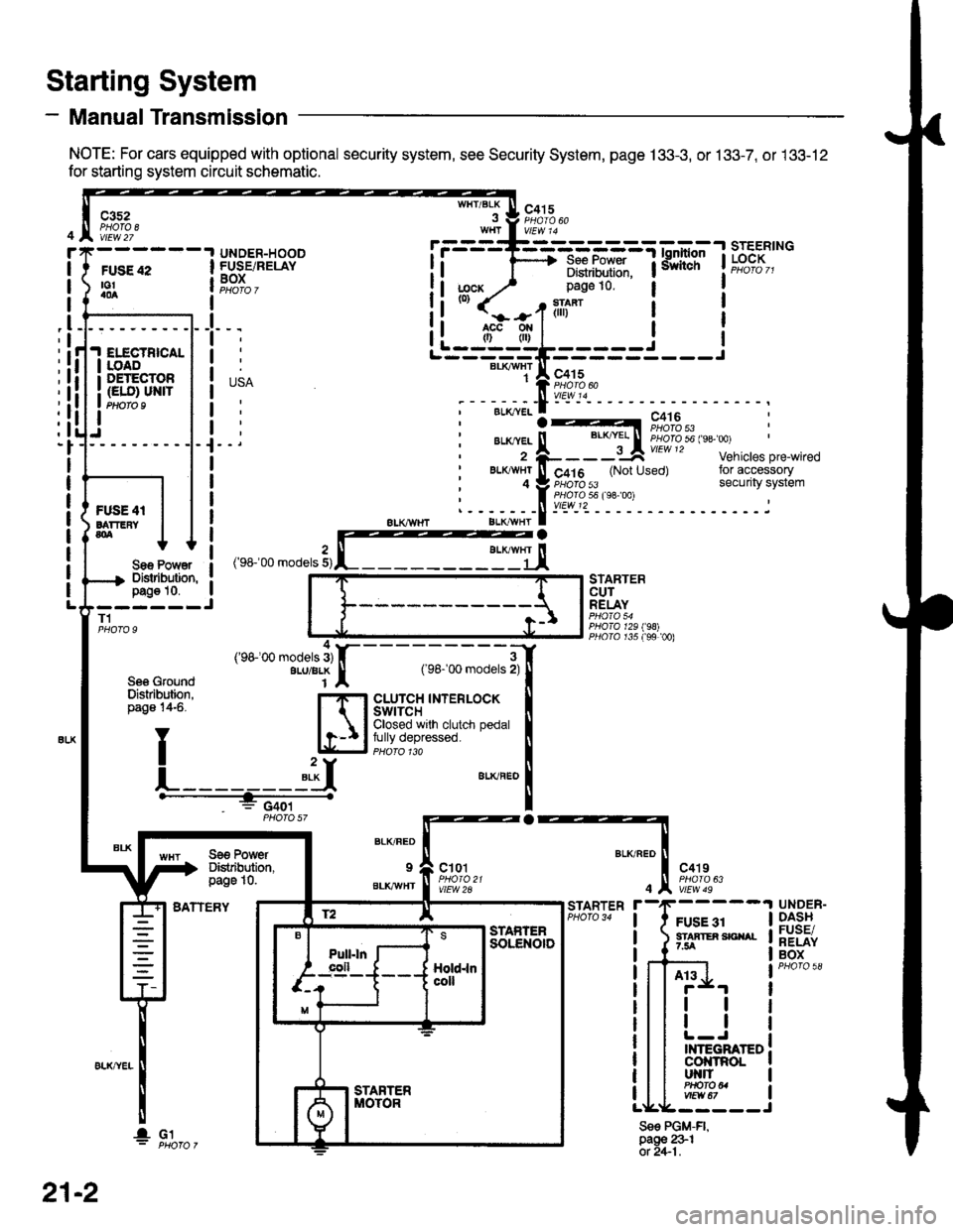
- Manual Transmission
NOTE: For cars equipped with optional security system, see Security System, page 133-3, or 133-7, or 133-12
for starting system circuit schematic.
Starting System
c3s2PHOTA 8vtEw 27
WHT/BLKc415
FUSE 42to!a0a
UNDER-HOODFUSE/RELAYBOXI
I
I
_l
IELECTBICALIOADDETECTOR(ELO) UN|TPtloro I
Sae Po'/Y€rDislibution,pag€ 10.------JT1
Se6 GroundDislribution,page 14-6.
BATTERY
STARTERCUTRELAY
PHO|A 129198)PllO|O r35 f99 00)
a
BLK/FED
9
BLKAVHT
ct01
vlEW 2A
c4't9
vtEw 49
FUSE 31STAATER SICIIAL7.5A
STARTER
4
Sse PGM-FI,page 231ot 2+1.
UNDER-DASHFUSE/RELAYBOX
At3
tl
tl
INTEGRATEDcol{tRoLut{llPHO|O U
r.------T-------------=;-*^:-lsrEERtNG
I i 1'----> R*.|?xf: iiiliffi' t"t%?I,,I Distribulion.1j;cx y' page 10.(0)
it-jtr'tl i
j
r---_-_€rx^,:jF;f
;-;:.==:t A r,+lo'tii:,J?"""
;--;*;.-f -- ^.:---.---1--
,'rr-'OO .o0"," 3,rffiEj,
---;;;;i[
cLUrcH TNTERLOCK tClosed wrlh clutch pedal Ifully depressed. llPHoro 1ra I"**"
!
Se€ PowerDistibution,page 10.
4('98100 models 3)ALU/BLK
f2 lE--r.---?q_l srAFrEn
21-2
I- G1
Page 1881 of 2189
NOT-E: Fu^se.31 is HO-f-with lgnition Switch in START (tD and clutch pedat depressed orA"iT Gear Selector in PARK (P) or NEUTRAL (N), see Siarting Systeni, page 2i or 21-2.
See Int€oratedControl Jnit.page 70.
UNDER-OASHFUSE/RELAYBOXPHOTO 58
c420
vtEw 53
PGM-FIMAINRELAY
vtEW 18
|- flrn*',
""-"'l
""^"*l *L
I
016Y5/D16Y8 D16,
;-ensnewrh",r-t :--*f 3l3yi:131ffi,-'' ---
I H;[h- N
i ii jt
lilT:{xsl I
ffifi:iil:"'"" il
-UTtl
i ryffi$il: i i ffifrffi ,,1 _,_:_____r,"*,
,A124 , , A14A, A13A ' 416A C6APOWERTRAIN, , ,^lAcy) (iAcvP) (rAcv N) | crnt $rs): I rAurr'arve , i r--.-, : Fuel pump control Start input ! :rNGtNFi , nt;*Y:l"" , i r--r I Fuel pump conkol Stan input | ;'NG|NElr 'uv"nv' : , IAC valve controt ' ICONTROL\I , I MODULE
t'----- ':------------i l(PcMorEcM)
I t'�;[?,i?"*L------ ---J
(cont'd)
---l-lf -----=-------------=--:
i
"au*", IzI
23-1
Page 1896 of 2189
NOTE: Fuse 3l is HOT with lgnition Switch in START (lll) and clutch pedal depressed or
A'/T Gear Selector in PARK (P) or NEUTRAL (N), see Starting System, page 21 or 21-2.
FUSE 31SIAilEfi SIGT{AL7.fi
UNDER.DASHFUSE/RELAYBOXPHOTO 58See ldeoratodControl Unit,page 70.
1110c420
vtEv,/ 53
PGM-FIMAINRELAY
vlEW 18
-:f]'" l;;;,b"YEUG8N
I
vtEw 40
i fli,i{ry;g:l lr R;::i8i3ll:13rffi:-''
'r
I H[f#'-
il |r'ru*
ljT-.i|ff
| - Friofo 1id | | I | Plioio {- n, 1 Y LJirJ-J plroio 4s tot6v7, I I G552'lt:i:PHotosa
I [ :: ! 'l r------' er-xl iiar-xfi onrl
i*"1 l:"'l I :
: I i: I I :
iazsA ii eoA ers|' , ltol lcql.I POWERTRAIN,a1F--X-lo"i"r t, "u*t : (FLF)
! , lAcvatve I i rq;.,.-...,; : Fu€r pump controt s"liii'p", ! EHc,le:;w, ruEr PqrrPlJtrIulI , connot :; IAC vatve controt , ! CONTROL
(cont'd)
24-1
Page 1907 of 2189
Programmed Fuel Injection System (PGM-F|) (D1685)
NOTE: Fuse 31 is HOT with lgnition Switch in START (lll) and A'/T Gear Selector in PARK (P) or NEUTRAL (N),
see Starting System, page 21-1 .
@
ii6iir-
- -TFU'E;--- - -
I gI3'5"
y#*i[HtF{,iiH.frIHHi Jiffi" !['.iF{,$SNALr5a Y 7.54| - See Inleqrat€dSse Pow€r | --+ ffii;l'i; -- | Phoro 58i ffi ffi:- |EHF? i I
p--',b"
I iffij*,**.,* iFE^l
SACI( UP7,ta
'[-------------'[&T:1,
L.[E"Jj!i_.f;ff:]_j
*L:*
ilTrr,*ii "",""[*=
{ {-
--
;[n*n-
--ftr-'lf
tlGFNYEI
T HI I
rv
J &l?3.,"","'o-,rr ! ,o"on
! #""?,* I
'rT#
*"ll
'fi-----n
h,T5$B.I
J J lvA!::, !
[--iI I
!tl
I onr I can ver- | er-u onn
Itt
A arsl rrsl a24
;t--7;,i----&;-----{IAC valve mnt.ol
;YN
IT/U
ll
v
ToBonlaclngpage
4
FED
I T------i:il;
,oln,.r I """-f-T:
-l-Lri | |d
l
wtl
Iil
i-,"ffifi
- - - - - - -- - -;s,nl - -ffi'J -.'"-
I Oac* rjp input input A
I
I
I|.-------
{F;H:{"
I
I
-"1
,,..!.'-^-*'! PowER-
f,mihHin.
I (PCM)
lif''?;"
25
BIU
Page 1912 of 2189
@----t UNDER.
I t FUSE 2s I p.4:!
| ) Iff" ses Power | ;"Eiii
I l------+ 3l'i:?'J:" tF,%.,L--*----il--l-J -
'o Y F;%.YELI v/Ew 55
f
--- - - - - - - - - - -;f '-iminats tz'zo1
I c+ lv'rwto
Y r--'1r-:-----'l GAUGE
see Power ! f* l"?i*,".. ! f,s";"ty"ttDisiribution, I , | vtEwTlpass10'6
i @$eFH,t* i
! T16r I
see see !y'c see I I
-ruil |See Startrnq ComDressor Charorno L--V---J----JFans System Conliols Syste-m - C5 y
I I I I
"".11-lro,..
| | | | o"no"n!f[?iSuo
GUN
I
BLUVHT
I
BLKnEo
I
GRNFED
f sVC131
*o I o, .1. o', ,l o.o .l
o"*o*l i[?1o"*
,r---U,a"i---strF-*-*"r"tr8*i-#%,.----;w;,---lneffi [it^'" tan control control ciutch reiay control Input | (pCM) -._ | puoroear AJc Atternaror Atternator l. iir*.i VSS rsquest FR controt I
i '[g3l i"R8!, ",gl,1o "'11'%, IrL------ --------Jc23 ll, l27Y "ur "rX
tlllBtUw}rI
I
BLU,FEo
I
w8r RED I wxr onr I
IIIIYYYY
See Vehicle See A,/C -'-dSpeedSensor Compressor(vss) contiot 3i:,""I"'n'"n
(cont'd)
25-5
I
Page 1917 of 2189
- How the Gircuit Works
With the ignition switch in ON (ll) or START (lll),
battery voltage is supplied through fuse 15 and
the BLI(WHT and BLK/YEL wire to the vehicle
speed sensor (VSS). The sensor is grounded by
the BLK wire to G1 01 . The speedometer and
other control units in the circuit supply about 5
volts to the BLU/WHT wire. The vehicle soeed
sensor (VSS) intermittently grounds the
BLUMHT wire which generates a pulsed signal
in it. The number of pulses per minute
increases/decreasos with the soeed of the car.
Reter to th€ Service Manual (Section 23, Electrical)
tor specific tosts or troubleshooting procedures.
33-1