Page 1575 of 2189
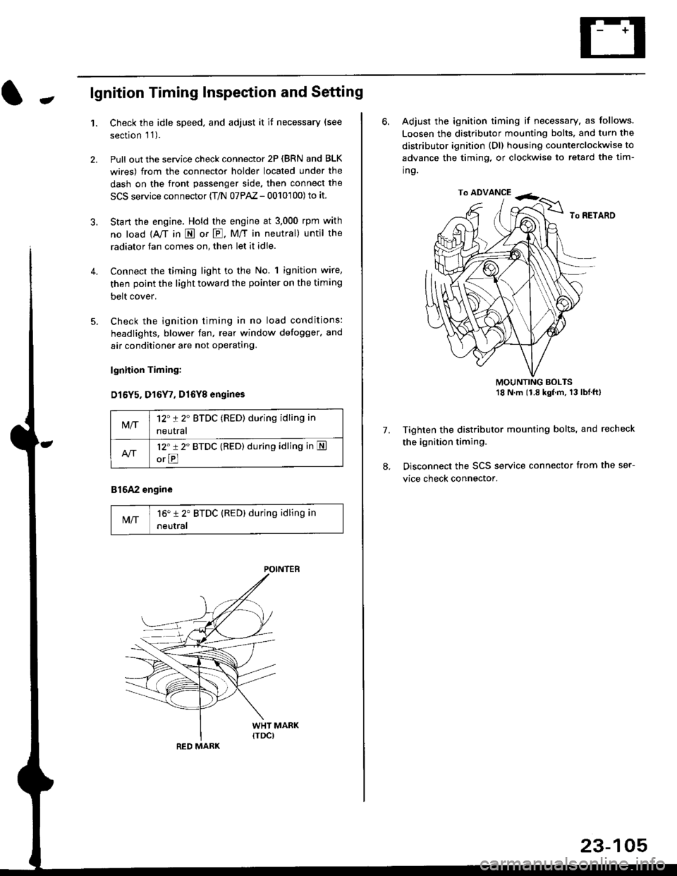
-lgnition Timing Inspection and Setting
1.Check the idle speed, and adjust it it necessary (see
section 'l '1 ).
Pull out the service check connector 2P (BRN and BLK
wires) from the connector holder located under the
dash on the front passenger side, then connect the
SCS service connector (T/N 07PAZ - 0010'100) to it.
Start the engine. Hold the engine at 3.000 rpm with
no load {A,/T in E or E. M/T in neutral) until the
radiator fan comes on, then let it idle.
Connect the timing light to the No. 1 ignition wire,
then point the light toward the pointer on the timing
belt cover.
Check the ignition timing in no load conditions:
headlights. blower fan, rear window defogger, and
air conditioner are not operating.
lgnhion Timing:
D15Y5. D16Y7, Dl6Yg engines
816A2 engine
MIT16" 12' BTDC (RED) during idling in
neutral
M/T12't 2" BTDC (RED) during idling in
neutral
l2'r 2" BTDC {RED) during idling in S
orE
POINTEB
RED MARK
23-105
ro ADVANCE -<;,
6. Adjust the ignition timing if necessary, as follows.
Loosen the distributor mounting bolts. and turn the
distributor ignition (Dl) housing counterclockwise to
advance the timing, or clockwise to retard the tim-
ing.
MOUNTING BOLTS18 N'm (1.8 kgfm, 13lblftl
Tighten the distributor mounting bolts, and recheck
the ignition timing.
Disconnect the SCS service connector from the ser-
vice check connector.
7.
Page 1584 of 2189
Charging System
Troubleshooting
lf the charging system light does not come onthe order listed below:
1. Baftery (see page 23-91)
2. Charging system light
3. Voltage
4. Alternator control system (USA)
5. Alternator/regulator
Charging Systom Light Test
or does not go off, or the battery is dead or low, test the following items in
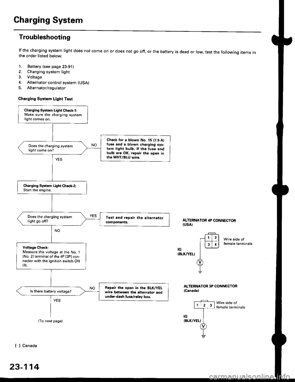
ALTERNATOR 4P CONNECTORIUSA)
Wire side offemale terminals
IG(8LK/YEL}
ALTERNATOR 3P CONNECTORlC.nadal
Wre side oftemale terminals
[ ]: Canada
23-114
Charging Svstem Light Check-l :lvlake sure the charging systemlight comes on.
Check for a blown No. 15 t7.5 A)fuso .nd a blown charging sys-tom light bulb. ll the fuse .ndbulb .re OK, ropair the open inth6 WHT/BLU wi16.
Does the charging systemlight come on?
Charging System Light Chec*-2:Start the enoine.
Does the charging systemlight go off?
Volta96 ChecklMeaslre the voltage at the No. 1lNo. 2l terminal of the 4P [3Plcon-nector with the ignition switch ONflr).
R6p.ir the op6n in the BLK/YELwire b€twsen tho altornator andund€r-dash tuso/.glay box.
ls there battery voltage?
Page 1587 of 2189
-
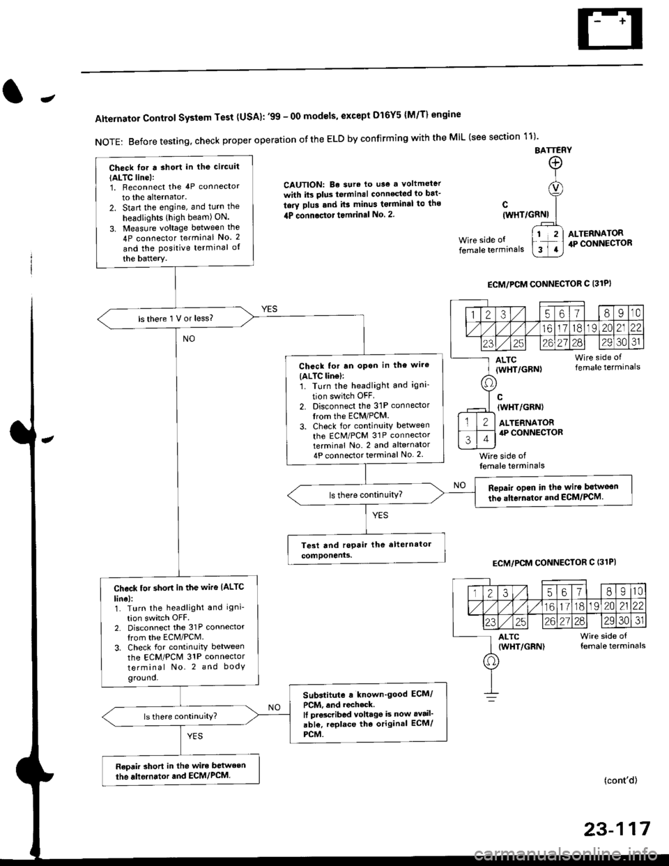
Alternator Control System Test {USA}: '99 - 0O models, except Dl6Y5 {M/T} engine
NOTE: Before testing, check proper operation ofthe ELD by confirming with the MIL (see section 11)'
BATTERY
CAUTION: Be sura lo use a voltmeter
with its plus te.minal conneqted io bat-
tery plus and it3 minus tgrminal to ths
4P connoctot tomrinal No. 2.
Wire side of
female terminals
c(WHT/GRNI
wire side offemale terminals
ALTERNATOR.P CONNECTOR
ECM/PCM CONNECTOR C 13lPI
ECM/PCM CONNECTOR C (31PI
(cont'd)
23-117
Check lor a sho.t in the circuit
{ALTC line):1, Beconnect the 4P connector
to the alternator.
2. Start the engine, and turn the
headlights (high beam) ON.
3. Measure voltage between the
4P connector terminal No. 2
and the Positive terminal of
the battery.
ls there 1 V or less?
Chcck for rn opon in the wire(ALTC lin6l:1. Turn the headlight and igni-
tion switch OFF
2. Disconnect the 31P connector
trom the ECM/PCM.
3. Check for continuity betlveen
the ECM/PCM 31P connectorterminal No. 2 and alternator
4P connector terminal No. 2
Repair opcn in the wire botweon
the alternstoi.nd ECM/PCM.ls there continuity?
Check tor short in the wire IALTC
line):1. Turn the headlight and igni-
tion switch OFF2. Disconnect the 31P connector
from the ECM/PCM.
3. Check for continuity between
the ECM/PCM 31P connector
terminal No. 2 and body
ground.
Substitute a known'good ECM/
PCM, and recheck.It prscribed voltagg is now avail'
abl€, replace tho original ECM/
PCM.
Raoair short in the wite between
the alle.nator and ECM/PCM,
1235618I10
/11611lo191 zo2122
23252621?82930JI
ALTC Wire side of(WHT/GRN) female terminals
o
Page 1588 of 2189
Charging System
Troubleshooting (cont'd)
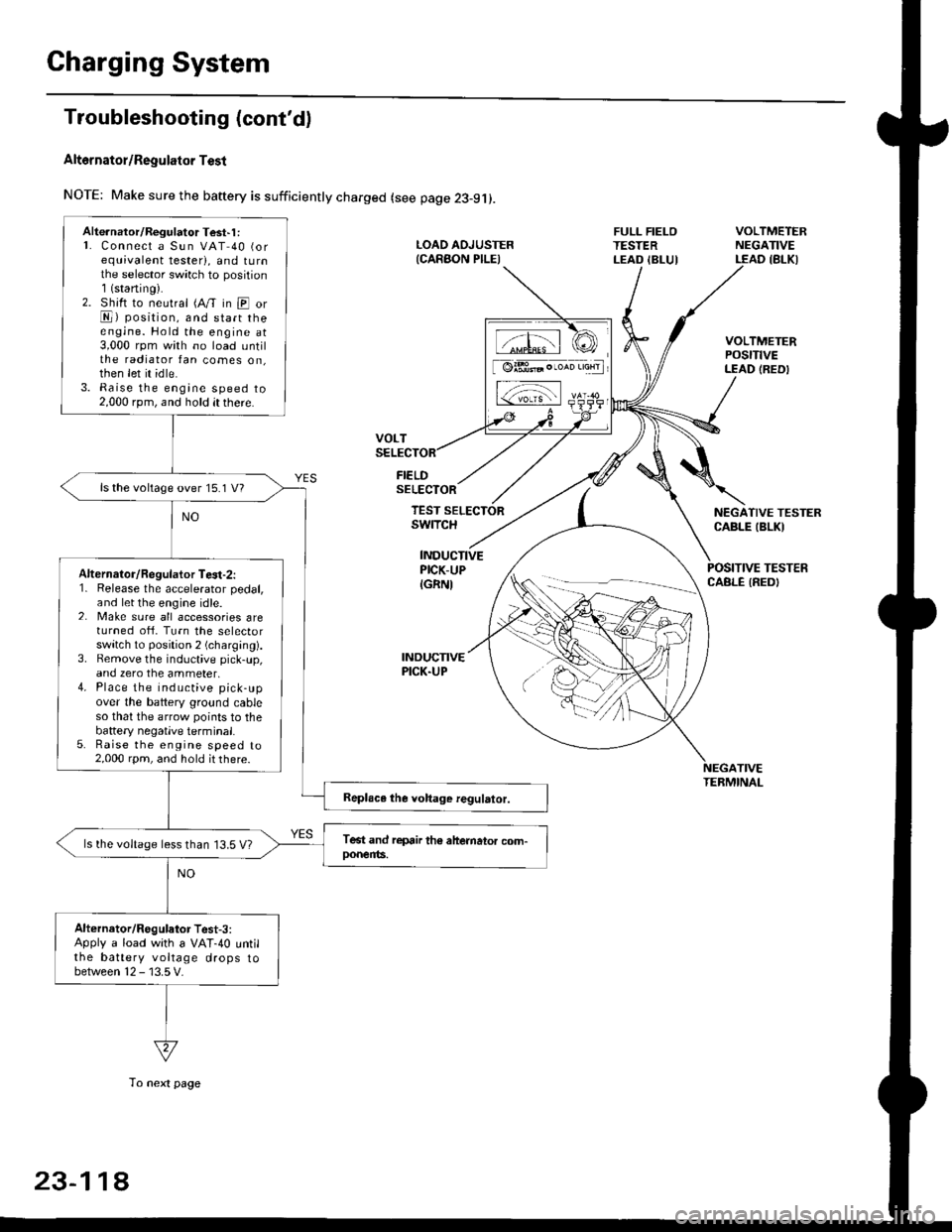
Alt6rnator/Regulator Test
NOTE: Make sure the baftery is sufficiently charged (see page 23-9j).
FIELDSELECTOR
LOAD AOJUSTER{CARAON PILEI
FULL FIELOTESTERLEAD IBLUI
VOLTMETERNEGATIVELEAD IBLKI
VOLTMETERPOStTtVELEAD (REDI
NEGATIVE TESTERCABLE IBLKI
POSITIVE TESTERCABLE IREDI
TEST SELECTORswrTcH
INDUCTIVEPICK-UP
IGRNI
INDUCNVEPICK.UP
TIVETEBMINAL
Alte.nator/Regulator Test'1 :L Connect a Sun VAT 40 (orequivalent tester), and tu rnthe selector sw;tch to position1(staning).2. Shift to neutral (A/T in E orE) position, and start theengine. Hold the engine at3,000 rpm with no load untilthe radiator fan comes on,then let it idle.3. Raise the engine speed to2,000 rpm, and hold it there.
ls the voltage over 15.1 V?
Alternalor/Regulator Te3t-2:1. Release the accelerator pedal,and let the engine idle.2. Make sure all accessories areturned ofi. Turn the selectorswitch to position 2 (charging).3. Bemove the inductive pick-up,and zero the ammeter,4. Place the inductive pick-upover the battery ground cableso that the arrow points to thebattery negatlve terminal.5. Raise the engine speed to2,000 rpm, and hold it there.
ls the voltage less than 13.5 V?
Alternator/Regulator Test-3:Apply a load with a VAT-40 untilthe battery voltage drops tobetween 12 - 13.5 V.
tffil rCI
[ @lBt* . ,*n 'aHrl
L-;-;l rs-
23-11A
To next page
Page 1612 of 2189
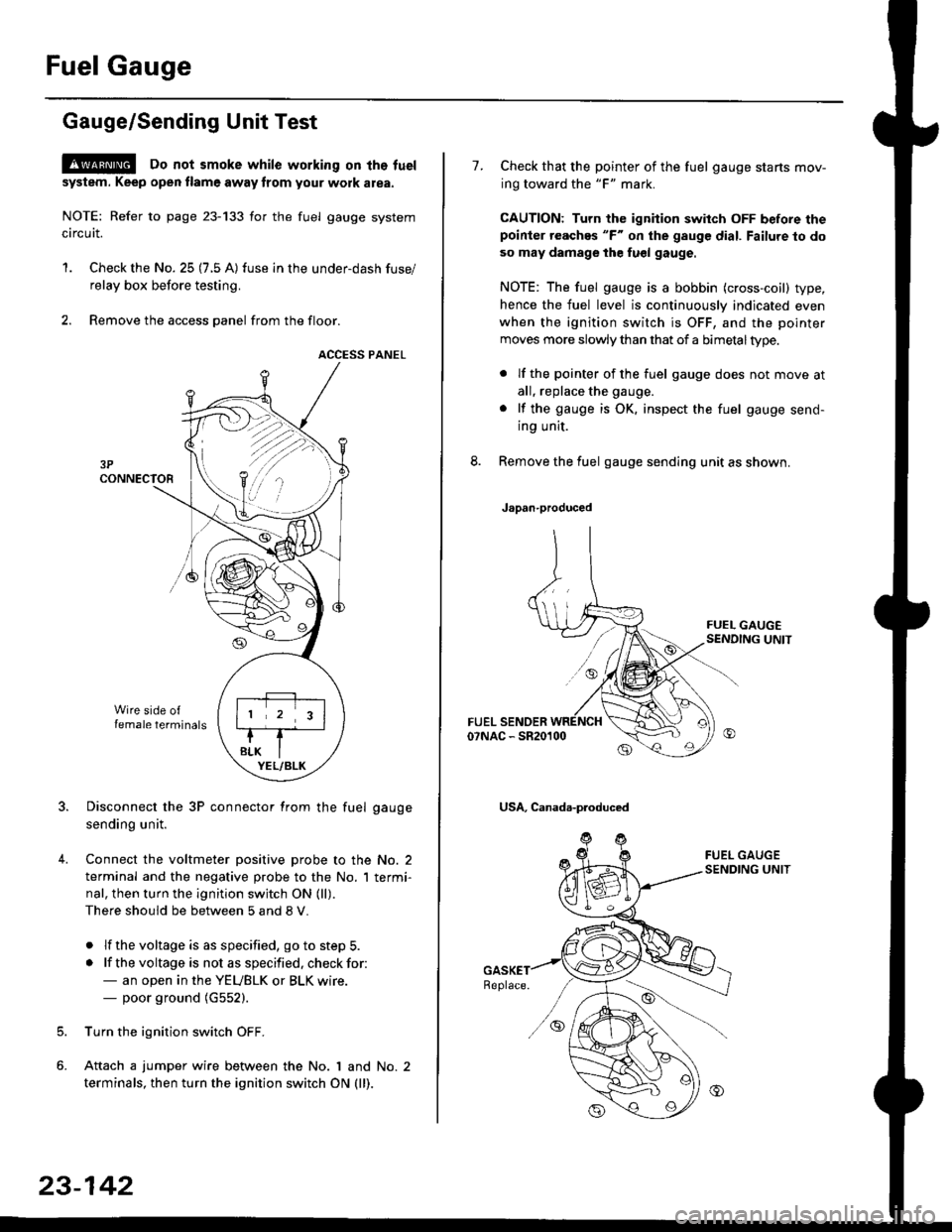
Fuel Gauge
Gauge/Sending Unit Test
!@ Do not smoke while working on tho fuel
system. Keep open tlame away trom your wotk atea.
NOTE: Refer to page 23-133 for the fuel gauge system
circuit.
'1. Check the No. 25 (7.5 A) fuse in the under-dash fuse/
relay box before testing.
2. Remove the access panel from the floor.
ACCESS PANEL
Disconnect the 3P connector from the fuel gauge
sending unit.
Connect the voltmeter positive probe to the No. 2
terminal and the negative probe to the No. I termi-
nal, then turn the ignition switch ON (ll).
There should be between 5 and 8 V.
. lf the voltage is as specified, go to step 5.
. lf the voltage is not as specified. check for:- an open in the YEUBLK or BLK wire.- poor ground (G552).
Turn the ignition switch OFF.
Attach a jumper wire between the No. 1 and No. 2
terminals, then turn the ignition switch ON (ll).
)\
23-142
1.Check that the pointer of the fuel gauge starts mov-
ing toward the "F" mark.
CAUTION: Turn the ignition switch OFF before thepoinier reaches "F" on ihe gauge dial. Failure to do
so may damage the fuel gauge.
NOTE: The fuel gauge is a bobbin (cross-coil) type,
hence the fuel level is continuously indicated even
when the ignition switch is OFF, and the pointer
moves more slowly than that of a bimetaltype.
. lf the pointer of the fuel gauge does not move at
all, replace the gauge.
. lf the gauge is OK. inspect the fuel gauge send-
ing unit.
Remove the fuel gauge sending unit as shown.
Japan-produced
USA, Canada-produced
Page 1625 of 2189
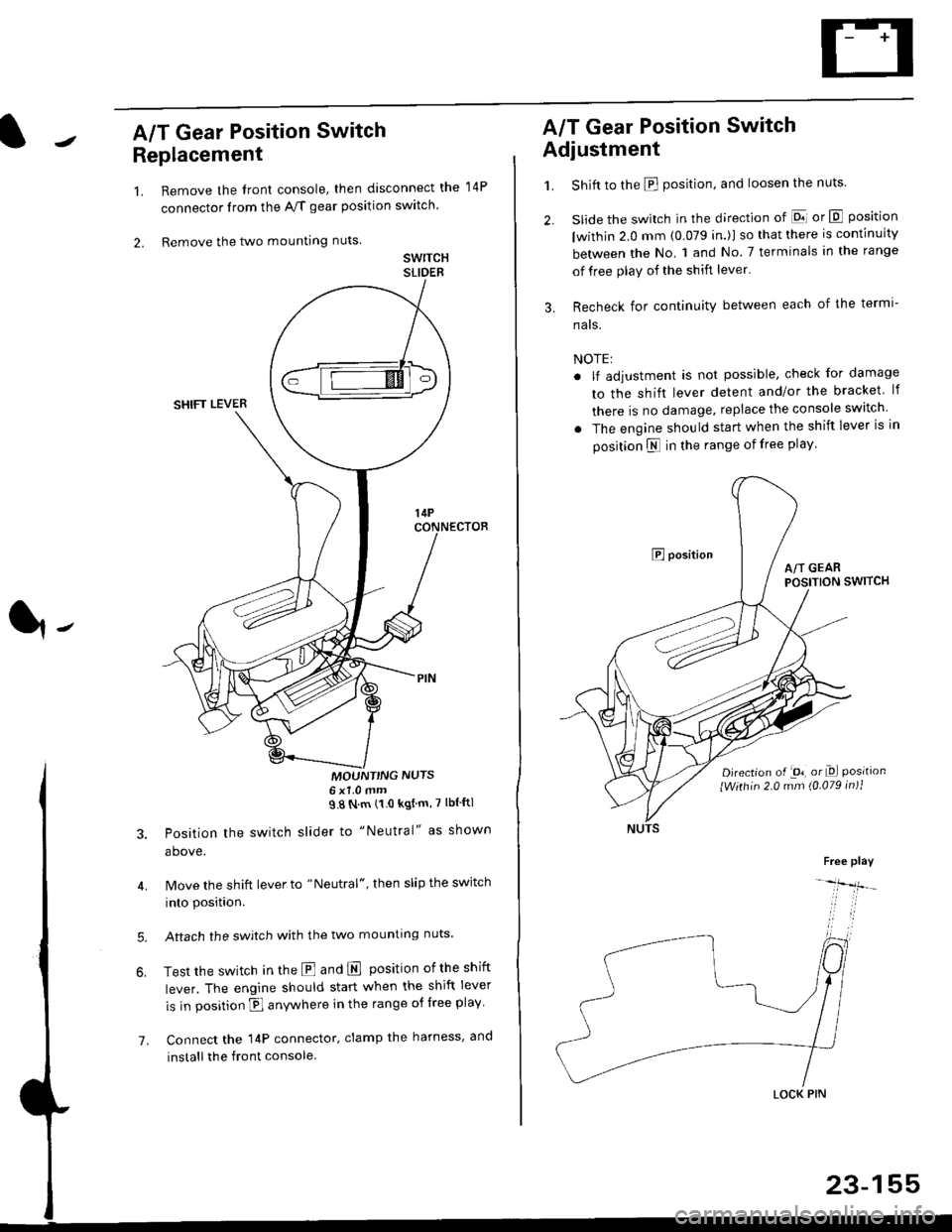
A/T Gear Position Switch
Replacement
1.
2.
7.
Remove the front console, then disconnect the
connector from the A/f gear position swltch
Remove the two mounting nuts
swrTcHSLIDEB
MOUNT'NG NUTS6x1 0mm98Nm(10kgtm'7lblftl
Position the switch slider to "Neutral" as shown
above.
Move the shift lever to "Neutral", then slip the switch
into position.
Aftach the swjtch with the two mounting nuts.
Test the switch in the E and E position ofthe shift
lever. The engine should start when the shift lever
is in position fl anywhere in the range of free play
Connect the 14P connector, clamp the harness, and
install the front console
14P
A/T Gear Position Switch
Adjustment
1.
3.
Shift to the E position, and loosen the nuts.
slide the switch in the direction of El or E position
lwithin 2.0 mm (0.079 in.)l so that there is continuity
between the No. 1 and No 7 terminals in the range
of free play of the shift lever'
Recheck for continuity between each of the termi-
nats.
NOTE:
. lf adjustment is not possible, check for damage
to the shift lever detent and/or the bracket lf
there is no damage. replace the console switch
. The engine should start when the shift lever is in
position N in the range of free play
E positionA/T GEARPOSITION SWITCH
Djrection of -on, or Dl Positionlwithin 2.0 mm (0.079 in)1
Free play
-lfr-
LOCK PIN
23-155
Page 1627 of 2189
(A,4)
A,T GEARPosrfloN swlrcH _ _(Closed h posilon l?l ot [!l )
BLU/BLK -> [h'#f- |COMEINATIONLIGHT SWITCH
V
IREO/GRN
UNDEF.DASH FUSEi RELAY BOX
a
E
YEL
I
A iEi,I,B"'T
vll".i,l
| ,rr.nrorro .orrro, ,*,,
tt-
t(
rffi
|
BEMI\DEB crqcurl
lm
| /t I
tffinEoTsru REDTBLU BLIJ/RED clnculr
-neoieru | ,,-,r.0 J
l, "ulTo
/fP /Itr\
YVI onrveqs I or rtor
l3fifl&''' l5frl'.'
l (3'&T' 8iytr") l
(3&Y fiti'fJ"fl )
BLK BLK
TT
c552 G401
I
. BRAKE FLUIDLEVEL SWITCH. PARKING ERAKEswrTcH (usA)
' CEILING LIGHT. KEYLESS RECE VER CIRCUIT(ln lhe audio unil")
..aorr,rro Y
A
Iu$ut,""'
I3fif'�3#3trr,)-::
DRIVER'SDOOFswtTcHfolosed : Door open )(Open :Doordosed/
STARTERCUT FELAY
a
-
GFNi RED
23-157
Page 1630 of 2189
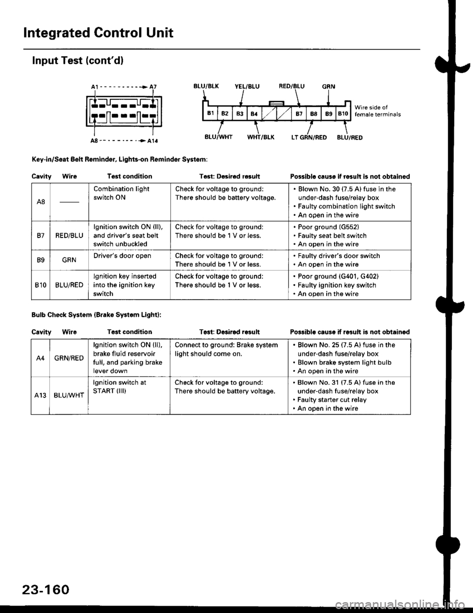
Integrated Gontrol Unit
Input Test (cont'dl
A8--------.--all
Key-in/Seat Belt R€mind€r, Lights-on Reminder Systom:
Cavity WireTest condhion
Bulb Check System (Brako System Light):
Cavity WireTest condilion
Tost: D€sirod r€guh
T6st: Dosirad result
Possible cause if result is not obtained
Possibls cause if rasuft b not obtainod
A8
Combination light
switch ON
Check for voltage to ground;
There should be battery voltage.
Blown No.30 (7.5 A)fuse in the
under-dash fuse/relay box
Faulty combination light switch
An open in the wire
B7RED/BLU
lgnition switch ON (ll),
and driver's seat belt
switch unbuckled
Check for voltage to ground:
There should be 1 V or less.
Poor ground (G552)
Faulty seat belt switch
An open in the wire
B9GRNDriver's door openCheck for voltage to ground:
There should be 1 V or less.
. Faulty driver's door switch. An open in the wire
Bl0BLU/RED
lgnition key inserted
into the ignition key
switch
Check for voltage to ground:
There should be 1 V or less.
Poor ground (G401. G402)
Faulty ignition key switch
An open in the wire
A4GRN/RED
lgnition switch ON {ll),
brake fluid reservoir
full, and parking brake
tever oown
Connect to ground: Brake system
light should come on.
Blown No.25 (7.5 Alfuse in the
under-dash fuse/relay box
Blown brake system light bulb
An open in the wire
A13BLUA/1r'HT
lgnition switch at
START (III)Check for voltage to ground:
There should be battery voltage.
Blown No.31 (7.5 A) fuse in the
under-dash fuse/relay box
Faulty starter cut relay
An open in the wire
23-160