1997 HONDA CIVIC Start
[x] Cancel search: StartPage 1718 of 2189
Cruise Control
t
D=
t
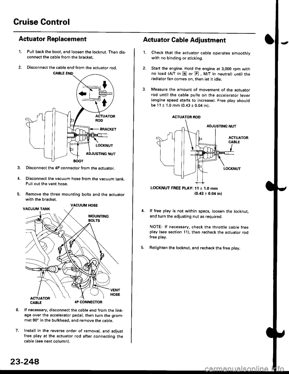
Astuator Replacement
1.Pull back the boot, and loosen the locknut. Then dis-
connect the cable from the bracket.
Disconnect the cable end from the actuator rod.
Disconnect the 4P connector from the actuator.
Disconnect the vacuum hosa from the vacuum tank.Pull out the vent hose.
Remove the three mounting bolts and the actuator
with the bracket.
CABTI aP CONNECTOR
lf necessary, disconnect the cable end from the link-age over the accelerator pedal, then turn the grom-
met 90' in the bulkhead, and remove the cable,
Install in the revers€ order of removal, and adjust
free play at the actuator rod after connecting thecable (see ne)d column).
7.
VACUUM HOSE
23-244
1.
Actuator Cable Adjustment
Check that the actuator cable operates smoothlywith no binding or sticking.
Stan the engine. Hold the engine at 3,000 rpm withno load (Afl'in N or E, M/T in neutral) untit theradiator fan comes on, then let it idle.
Measure the amount of movement of the actuato.rod until the cable pulls on the accelerator lever(engine speed starts to increase). Free Dlay shouldbe 11 t 1.0 mm (0.43 I 0.04 in).
LOCKNUT FREE PLAY: 11 1 1.0 mm
{o.i|:l r 0.oit in}
lf free play is not within specs, loosen the locknut,
and turn the adjusting nut as required.
NOTE: lf necessary. check the throttle cable freeplay (see section 11). then recheck the actuator rodfree play.
Retighten the locknut, and recheck the free play.
ACTUATOR ROD
Page 1737 of 2189
)
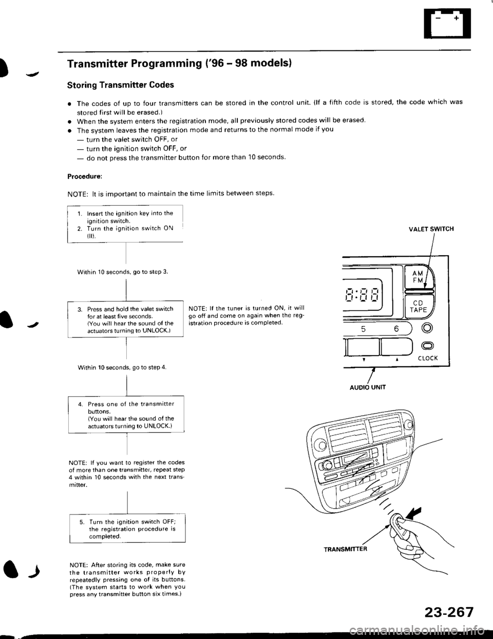
Transmitter Programming ('96 - 98 models)
Storing Transmitter Codes
. The codes of up to four transmitters can be stored in the control unit. {lf a {ifth code is stored, the code which was
stored tirst will be erased.)
. When the system enters the registration mode, all previously slored codes will be erased.
. The system leaves the registration mode and returns to the normal mode if you
- turn the valet swirch OFF, or
- turn the ignition switch OFF, or
- do not press the transmitter button for more than 10 seconds
Procedure:
NOTE: lt is important to maintain the time limits between steps
VALET SWITCH
NOTE: lf the tuner is turned ON, it willgo off and come on again when the reg-
istration procedure is completed-
l-l
NOTE: lf you want to register the codesof more than one transmitter, repeat step4 within 10 seconds with the next trans'mitter.
NOTE: After storing its code, make sure
the transmitter works properly bYrepeatedly pressing one ot its buttons.(The system starts to work when Youpress any transmitter button six times-)
TRANSMTITTER
23-267
--
Insert the ignition key into the
ignition swatch.Turn the ignit;on switch ON
flr).
Within 10 seconds, go to steP 3.
3. Press and hold the valet switchfor at least tive seconds.(You will hear the sound of theactuators turnang to UNLOCK.)
Within 10 seconds. go to step 4.
4. Press one of the transmitterbuttons,(You will hear the sound of theactuators turning to UNLOCK.i
AUDIO UNIT
Page 1817 of 2189

Contents
How to Use This Manual ICircuit Schematics (see Circuit Index)Fuse/Relaylnformation 6Ground-to-Componentslndex 6-6ComponentLocationPhotooraohs 201Conriector Views 202
Circuit Index
Accessory power socket 155Air conditionerAir delivery'96198 models 61'99-'00 models 61-2Blower controls'96198 models 60'99100 models 60-1Compressor controls 62Fans 63Anti-lock brake system (ABS) 44A/T gear position indicatorCVT 89All except CVT 89-1Automatic transmission controlsAll '96-'98 models except CVT and GX 39All '99100 models except CVT 39-8All GX models 39-8'96-'�98 CVT 39-4'99100 cw 39-12Back-up lightsCoupe and Sedan 110Hatchback l'10-1Brake lightsAll Coupes and'96-'98 Sedans 110-15'99-'00 Sedans 110-16Hatchback 110-17Brake system indicator light'96198 models 7'1'99100 models 71-1Ceiling light 114-3Charging system 22Condenser fan 63Console lights 114Cruise control 34Dash lights 114Daytime running lights 110- 13Engine coolant temperature gauge 81-1Fog lights 110-10Front parking lights 110-2Fuel gauge 81-1Fuse/relay boxUnder-dash 6Under-hood 6-4Underhood ABS 6-3Gauges 81Ground distribution 14Ground-to-Componentslndex 6-6Hazard warning lightsAll except '99100 Sedans 110-6'99100 Sedans 110-8Headlights 110-12Headlight switch 100Heater - See Air ConditionerHorn'96197 models 40'98 model 40-1'99100 models 40-2lgnition key reminder 73lgnition systemAll '96198 models except Dl685 20All '99100 models except D16Y5 with Mn 2O-2All D1685 engines 20-2'99-'00 D 16Y5 with M/T 20
lndicators 80Integrated control unit 70lnterlock systemAll except'96J98 CVT 138'96198CVT 138-1License plate lightsAll Coupes and '96-'98 Sedans I l0-3'99100 Sedans 1 10-4Hatchback 110-5Low fuel indicator light 74Moonrool'96197 models |22'98-'00 models 122-1Odometer 81Oil pressure indicator light 80-3Power distributionBattery to ignition switch, fuses, and relaysFuses to relays and components 10-2Power door locksAll models without keyless entry 130'96-'98 models with keyless entry 130-2'99100 models with keyless entry 130-12Power mirrorsWithout detogger 141With defogger '141-2
Power windows 120Programmed fuel injection system (PGNr-Fl)All '96-98 models except D1685 23All '99-'00 models except D16Y5with M/T and D1685 24All D1685 engines 25'99100 D16Y5 with M/T 23Radiator fan 63Rear window defogger'96-,98 models 64'99100 models 64-1Seat belt reminder 73Security system'96.'98 USA HX, LX, EX 133'96-'98 Canada EX, Si 133'99TOO USA HX, LX, EX, DX.V Si 133-4'99100 Canada EX, Si 133-4All CX and DX models 133-8Speedometer 81Starting systemA./T (All except Dl685) 21A"/r (D16Bs) 21-1Manualtransmission 21-2Slereo sound system 150Supplemental rastraint system (SRS) 47Tachometer 81TailliqhtsAllboupes and'96-'98 Sedans 110-3'99100 Sedans 1 10-4Hatchback 110-5Trunk light 114-3Turn signal lightsAll except'99100 Sedans 110-6'99-'00 Sedans 1 10-8Vehicle speed sensor (VSS) 33Wiper/washerFront 91Rear 92
10
Page 1820 of 2189
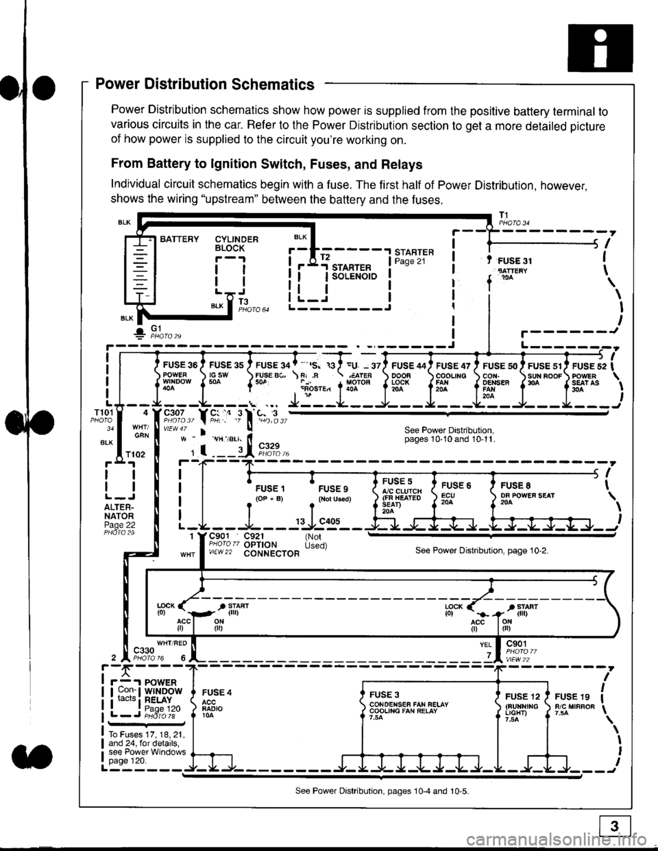
Power Distribution Schematics
Power Distribution schematics show how power is supplied from the positive battery terminal to
various circuits in the car. Refer to the Power Distribution section to get a more detailed picture
of how power is supplied to the circuit you're working on.
From Battery to lgnition Switch, Fuses, and Relays
Individual circuit schematics begin with a fuse. The first half of Power Distribution, however,
shows the wiring "upstream" between the battery and the fuses.
CYLINDERBLOCK
tl
tlL.lt J
",-* f ]fo,o
i BATTERY
IIII
-
----------------Y-?-
ruse so I ruse as I ruse ga | ' ,s. ,a I =u. - srl ruse aai ruse qr I ruse so I ruse sr i ruse iapowEF csw FUsE Bc, \F,.n .;,cren ooon \coounc cor,r. \sun noor powrnw'NDowf50a {* .i1-;.*"1liT""fi3f* f5# fffi'*"f'* fS?'*
- - -L - - -. ... Ji - -.J.- - - -e- - -l. - - -La - J- - - I - - -
"";%,, Y rtr,' .9 l' -%,t",,vtEw47 I ! See Power Dastribution,w - vH-,alr. lt - pages 10,10and 10-11.
' I ---il 9,1?-l--4F--?-
i I
t.urr, 'rrr.,
t i!?'.,,?"" t::=. l ty::.1----.-
-
i
a I r(op-B) .{Noru3€d) J$ifl#ii Jtocl }3fo**."".o'
t -L - - -L - - -: rJ:e'- - -Ei s+s-r -.Fl-J-Jrr.-.
It-STARTER | !Pase 21 ! t FUSE 31I "rn*i
I f
*
i.Jr;-t
i L_i***'" iL-------J
ilr------!
FUSE /I4 ' FUSE 47 ' FUSE 5{' ' FUSE 51' FUSE 52
rlr
OOOB \COOLING CON. \SUN BOOF FOWER
t3f* f5# fffi*" f'* fs?'*
See Power Dastribution,pages 10'10 and 10-11.
T101
34
ALK
4
GAN
I
I
I
I
I\
\I
I
I
FUSE 8DF POWEF SEAT204
FUSE 6ECU204
FUSE 5A/C CLUICH(FN HEATEDSEAD204
C901 C921 {NotPHoro zz OPTION Used)v/EW22 CONNECTOBSee Power Distnbution, page 10-2.
1
FUSE 4
FADIO104
c901
vlEw22
FUSE 12(BUltNrrGLIGHT)
FUSE 19R/C MIRROF
YEL
7
i-f,r-- 't PowERI uon- I Wlt{DOWi racrs i RELAY. t P^da 1tL-J P;dr1ii-
FUSE 3CONOENSEF FAN RELAYCOOLING FAN RELAY
To Fuses 17, 18, 21,and 24, for details,see Power Windowspage 120.a
ll
ll
ALTER-NATORPage 22
f102
c330
See Power Distribution, pages 10-4 and 10-5.
Page 1824 of 2189
Connector Views
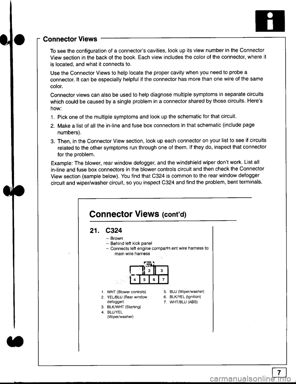
To see the configuration of a connector's cavities, look up its view number in the Connector
View section in the back of the book. Each view includes the color of the connector, where it
is located, and what it connects to.
Use the Connector Views to help locate the proper cavity when you need to probe a
connector. lt can be especially helpful if the connector has more than one wire of the same
cotor.
Connector views can also be used to help diagnose multiple symptoms in separate circuits
which could be caused by a single problem in a connector shared by those circuits. Here's
how:
1. Pick one of the multiple symptoms and look up the schematic for that circuit.
2. Make a list of all the in-line and fuse box connectors in that schematic (include page
numbers).
3. Then, in the Connector View section, look up each connector on your list to see il circuits
related to the other symptoms run through one of them. lf they do, inspect that connector
for the oroblem.
Example: The blower, rear window defogger, and the windshield wiper don't work. List all
in-line and fuse box connectors in the blower controls circuit and then check the Connector
View section (sample below). You find that C324 is common to the rear window defogger
circuit and wiper/washer circuit, so you inspect C324 and find the problem, bent terminals.
5.
6.
7.
1.
2.
WHT (Blower controls)
YEUBLU (Rear window
defogger)
BLK,ryVHT (Starting)
BLU/YEL(Wiper/washe0
8LU (Wiper/washed
BLfiEL (lgnition)
WHT/BLU (ABS)
Connector Views (cont'd)
21. C324
Brown
Behind left kick panel- Connects left engine compartry'ent wire harness to
main wire harness
ll,ll,
567
Page 1826 of 2189
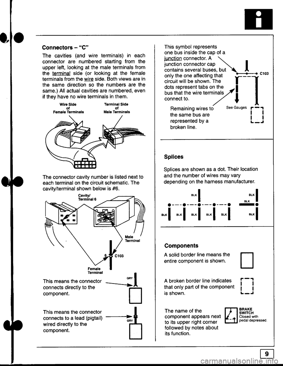
Connectors - "C"
The cavities (and wire terminals) in each
connector are numbered starting from the
upper left, looking at the male terminals trom
the terminal side (or looking at the female
lerminals f rom the wire side. Both views are in
the same direction so the numbers are the
same.) All actual cavities are numbered, even
if they have no wire terminals in them.
Terminal SldeolMale Tsrminals
{
T
_A
Wlre SldeotFemalg Trrmlnala
The connector cavity number is listed next to
each terminal on the circuit schematic. The
cavity/terminal shown below is #6.
Terminal
This means the connector
connects directly to the
componenr.
This means the connector
connects to a lead (pigtail)
wired directly to the
component.
Cavlty/Termlnsl 6
only the one affecting that
ciriuit will be shown. The f
--f
!!*!"*F"#fi5'�;,Hy4
I
Remaining wires to
the same bus are
represented by a
broken line.
The name of the
component appears next
to its upper right corner
followed by notes about
its function.
This symbol represents
one bus inside the cao of a
iunction connector. A \
lr"ctb. connectorcap |contains several buses, but Ac103
tl
tl
*-
I ",.-"* I
a---a---a--- a--- o -a
*"1 *-l *-l *-l *"1 *-l
See Gauges
Splices
Solices are shown as a dot. Their location
and the number of wires may vary
depending on the harness manufacturer.
Components
A solid border line means the
entire component is shown.
A broken border line indicales
that only part of the component
is shown.
t_J
ll
ll
BRAXEswtTcHClosed wilhpedaldepressed.
Page 1838 of 2189
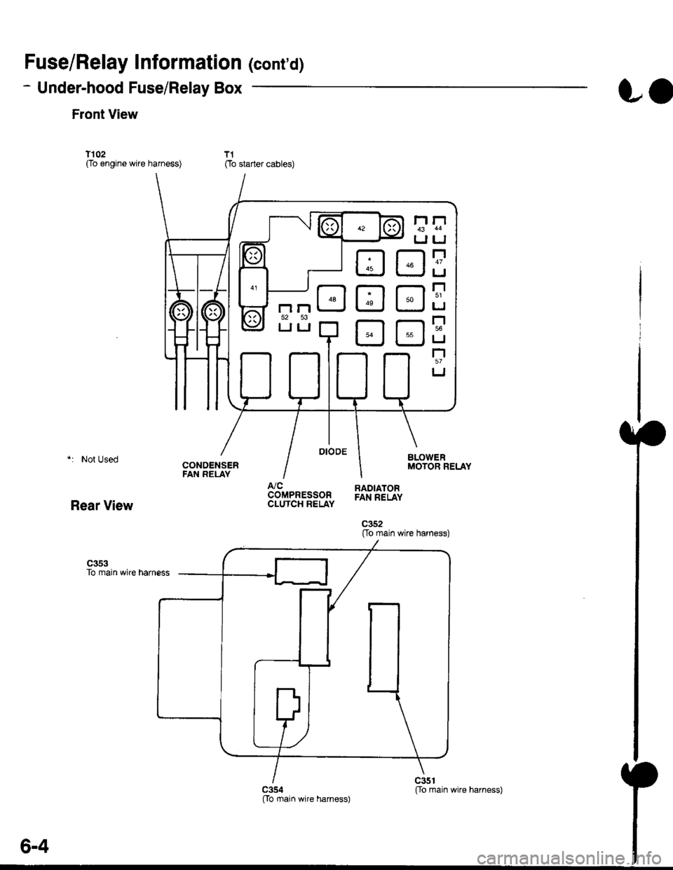
Fuse/Relay Information lcont'd)
- Under-hood Fuse/Relay Box
Front View
T'102(To engine wire harness)
LO
T1Oo starter cables)
*: Not Used
Rear View
c353To main wire harness
DE
tr
tr
tr
t-l
IJ
n
tJ
t-l51
IJ
n
IJ
n5T
IJ
[[o main wire harness)
6-4
ffo main wire harness)fto main wire harness)
Page 1842 of 2189
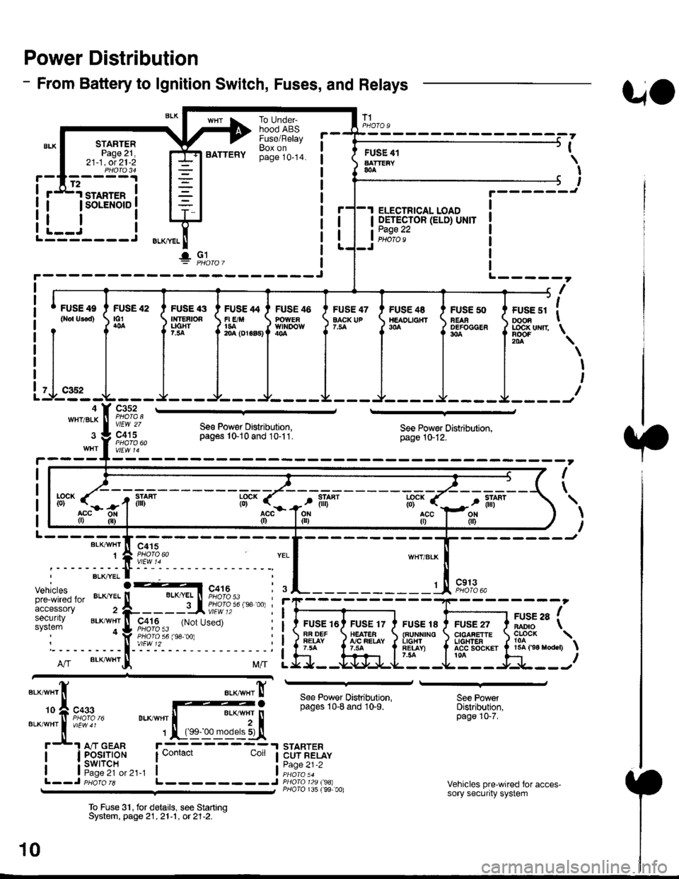
Power Distribution
- From Battery to lgnition Switch, Fuses, and Relays
STARTERPage 21,21-1, ot 21-2
.d1.ro"rr" i
I lsoLENorD I
FUSE 42tG1
BATTERY
To UndeFhood ABSFuse/RelayBox onpage 10-14.
FUSE 47EACK UP
T1
FUSE 41AATTEiY&A
I OETECTOR (ELD) UNIT
tii::.':
UO
PHOfO U
,
I
I
I
t.------J
ELECTRICAL LOAD
i--i rL---- J ELKml
!" Gl
FUSE 4e
0ro{ Urod)FUSE '13Ir|]EAtOAUGHT?.:ta
FUSE 46POWEaWll'IDOW
FUSE /t4
r| E/M1{rA204 (DrGa5)
FUS€ 48TtEADL|a}fT9|'A
FUSE 50NEAAOEFOCGER304
+------, f| ',
I ruse sr I oooa I
J LOC|( uNrr \
il-.4WHT/BLK
Itr '\
\
I
I
I
c352
vlEW 27
c415Se€ Pow€r Distribution,pag6s 10-10 and 10-11.See Power Distribution,page 10-12.
I
\
L------BLK/VI/HT
1
--------Jc415
Vehiclespre-wired foraccessorysecuritysystem
c913PHOTO 6A
FUSE 16AR DEFFEIAY
FUSE 17HEATEA!'/C FEIAY
FUSE 18{RUNNINOL|GHlFET.AY)7.54
FUSE 27CIGAFETTEL|oHTEAACC SOCKET ta
arse ra fBADIO \
?o?"* \15A ('94 raodcr)
ff".acc0)
llL--------J
See Power Distribution,pages 10-8 and 10-9.
STARTERCUT RELAYPage 21-2
P/lolo 135 (99 00)
See PowetDistribution,page 10-7.
Vehicles pre-wired for acces-sory security system
To Fuse 3'|, for delails, see StartrnqSystem, page 21,21-1 , ot 21-2. -
10