Page 1922 of 2189

Gruise Control (cont'd)
- How the Circuit Works
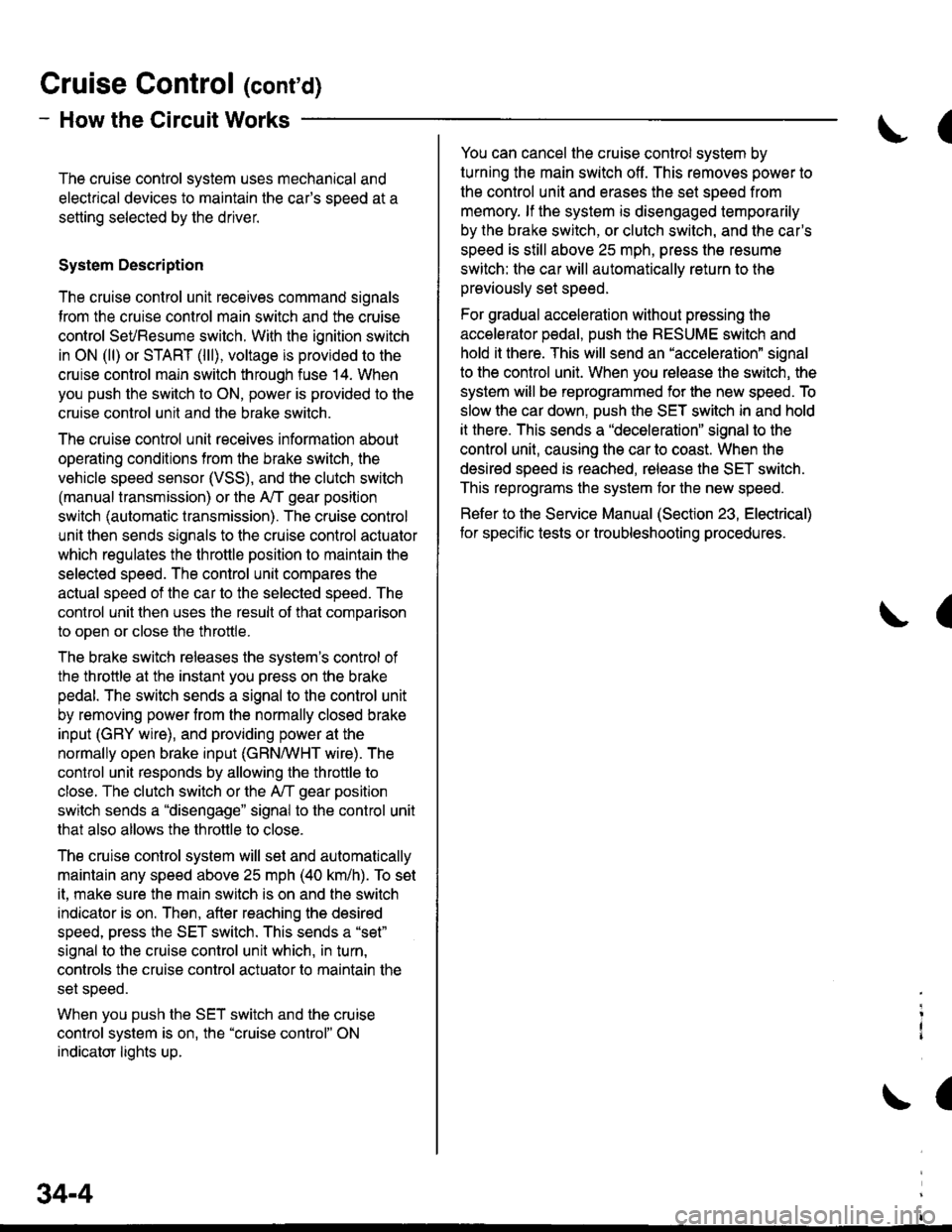
The cruise control system uses mechanical and
electrical devices to maintain the car's sDeed at a
setting selected by the driver.
System Description
The cruise control unit receives command signals
from the crurse control main switch and the cruise
control SeVResume switch. With the ignition switch
in ON (ll) or START (lll), voltage is provided to the
cruise control main switch through fuse 14. When
you push the switch to ON, power is provided to the
cruise control unit and the brake switch.
The cruise control unit receives information about
operating conditions from the brake switch, the
vehicle speed sensor (VSS), and the clutch switch
(manual transmission) or the A,/T gear position
switch (automatic transmission). The cruise control
unit then sends signals to the cruise control actuator
which regulates the throttle position to maintain the
selected speed. The conlrol unit compares the
actual speed of the car to the selected speed. The
control unit then uses the result of that comoarison
to open or close the throttle.
The brake switch releases the system's control of
the throttle at the instant you press on the brake
pedal. The switch sends a signal to the control unit
by removing power from the normally closed brake
input (GRY wire), and providing power at the
normally open brake input (GRN/vVHT wire). The
control unit responds by allowing the throttle to
close. The clutch switch or the A,/T gear position
switch sends a "disengage" signal to the control unit
that also allows the throttle to close.
The cruise control system will set and automatically
maintain any speed above 25 mph (40 km/h). To set
it, make sure the main switch is on and the switch
indicator is on. Then, after reaching the desired
speed, press the SET switch. This sends a "set"
signal to the cruise control unit which, in turn,
controls the cruise control actuator to maintain the
set speed.
When you push the SET switch and the cruise
control system is on, the "cruise control" ON
indicator lights up.
34-4
(
You can cancel the cruise control system by
turning the main switch off . This removes power to
the control unit and erases the set speed from
memory. lf the system is disengaged temporarily
by the brake switch, or clutch switch, and the car's
speed is still above 25 mph, press the resume
switch: the car will automatically return to the
previously set speed.
For gradual acceleration without pressing the
accelerator pedal, push the RESUME switch and
hold it there. This will send an "acceleration" signal
to the control unit. When you release the switch, the
system will be reprogrammed for the new speed. To
slow the car down. oush the SET switch in and hold
it there. This sends a "deceleration" signal to the
control unit, causing the car to coast. When the
desired speed is reached, release the SET switch.
This reprograms the system tor the new speed.
Refer to the Service Manual (Section 23, Electrical)
tor specific tests or troubleshooting procedures.
(
a
Page 1928 of 2189
aI
I coNrRoL
EcM EcM lllg?.Y.ERelernce control data control I H;,."voftase output ff.'nour a;i:;Y"*- lug'L - - - - JS- - - - - J't3'- - - iA25Y CgY C30Y
lL
I 1=,
-"'"'"1 ""1 "-l
rRANsM,ss,oN
,r, ,[ ", I ". I
"oou".-o'"[3fl!
NnEF) O[,!A) OMB)Beference ECM control ECM control D..r.i.^vollage data input data output ;;ii; vI
t
swrtch
CVT transmrssion conlrol solenoids signal DTC CVT grounds
j input outputlPcrr /pcl).t HLC LS I iHLC LS+l {SC LS-) tSC LS-) (SH Ls-i ISH LS-l ISOL INH' THBRK SWt {O'AG Hr {LGli {LGl) lPclr tpclj :
{*n*
:".,1 :"::.1 i.lnu+
',sk,-[lr*:[l*':t'
*?:?' """",.0-fr;rt.o,1^,, *'ig"#"t I""-t cw i
-"' iiio lr.'t l
lsel$tfis'! I !
izf-"{}Y
f,====i iiu:'" !
I ii,l;?:' i
lt r---L
4 9::1",- (cont'd)
39-s
PH.PL START SHIFTCONTFOL CLUTCH COITTROLLINEAR CONTROL LINEARSOLENOID LINEAR SOLENOIDSOL:NOID
Page 1936 of 2189
?uTi'i'------lUNDER.OASHFUSE/RELAYBOX
UNDER-HOODFUSE/RELAYBOXfI,€! PtfiP
f#rntt)See PowerDistribution,
iT;;*-l
rr:_i
y;lftr,.:{'
page 10-2.tJ---------J" Y 3,,t"?:"""""T
[']':.
i-?;;ffi;
i_f___
PGM-FIMAINRELAY
;;II
;;;I
c't0'l
vtEw 28
TI
":{
c130Oerminals l4-17)
vlEw 52
I . (rGP1) i 1rGP2) - I
Power input
..���������������
SeePGM,FI
POWER.TRAINCONTROLMODULE(PcM)PHO|O 86
(cont'd)
\!
CW hansm|ssion_ control solonoids Ground I
t (HLC LS-) THLCLS+) (SCLS-) (SCLS'I iSH LS I rSHLS+j ISOLINHI lPGr) (PO2) (LG1) rLG2r IL-------i:---- ---------J
-T1
Tj
:1 ;
lruffil
GRNBLII
cl16(Terminals8-14)
vlEW 39BLK
CVTTRANS.MISSIONSOLENOID
See GroundDistribution,page 14-2.
BRN/BLK
PH.PL START SHtF'CONTROL CLUTCH CONTNOLUN€AR CONTNOL LINEARSOLENOID UI{EAR SOLENOIDsoLEltotD
:_-:_-___1
-t
1-! |
Ti11:a__J
BRN/BLK
39-13
Page 1965 of 2189
Integrated Control Unit
NOTE: Fuse 31 is hot with lgnition Switch in START (lll) and clutch pedal depressed or A,/T Gear Selector in
PARK (P) or NEUTRAL (N), see Starting System, page 21,21-1, ot 21-2.
See BrakeSystemlndicatorli^hl
FUSE 3IstaaTEaSIGI{AT7AAI
I
I
I
I
I
\
\
\
\
\
\
I
I
I
I
I
I
/
S€s SiarlingSyslsm, pago 21,21-1. or 21'2.
SEs BrakeSystemlndicetorLight A6
SsaClharSrrESystom
Eog GoundDistlbution,page l,l-7.
L------3c420PHO|O 63vtEw 53
--r-r..r'
FED/BLU
SeeCeilingLightSee Seat Beltand lgnitionKey Remind€rs
t@
i'l-;;,-lH8B'r*| rrmn1gn I FUSEI
i f t*" ig8f"LJr____J PHOTO 7
u'lf tf,%,
S vtEw 3a
wHr/FED
| 3fl3,n'"n
wHr,FED I sYsteh
<--=- !t
,r"r,".0 | ,n"r,".u I
| .l B*?r:"" ,.!,.*,
Page 1967 of 2189

Brake System Indicator Light
- '96-'98 Models
NOTE: Fuse 31 is hot with lgnition Switch in START (lll) and clutch pedal depressed or A,/T gear selector in
PARK (P) or NEUTRAL (N), see Starting System, page 21 , 21-1, or 21-2.
a
FUS€ 31atAirEn8Gl{tt7.all
UNDER-DASHFUSE/RELAYBOXS€o Starling Sysl6m,pag6 21, 2l-1, or el-2,
FUSE 25
ffR s." Ponr"tDistribulion,page 10-6.
rry
I
;?l
r
I
I
I
I
I
I
I
c501PHOTO 60vtEw 55
Ss€ Pow6rDlstribution,page 1G6.
---.I GAUGE$os IndicatorsI ASSEMBLY
i',i!i,I2'
I
I
(slt--95.:l-_i
l8s: GRN/FEDr--- CW ----.
! 3 A cso3 :..^.,"..,"",^.;i "lir%?u' ' rRANsMls-sloN :! ll virw ro : CONTROL ;
99€ grqn'd | ! s I iiiiir^ , vtLw 6s
i o"^r"'o |
'i'jri
| "lw;t,b---4---- 31i3*:'. --l:ffiffi--i
i
---- -.L- J- -:g,tgLesr.l - ---- J--:- J--i : ! 3113'"0* | :-9tF":--T-tY-E;"41i'",
: : lsrss9l;-;?--q1Al" :L:W-J i
-----.1- J- -tlb$Lsr'{.i------ J--:- J--i : ! 31ffi "o* | i-trfr; - -
i
-TFr,lifu:i-|l - - .Tf"*;',r;,f'.F?f;l', i LTS-: :
i I ii
-""'"L--i:t--i3trFlr*n'"i
i mooule ficlrt) iI PHO|O 121 '
:! :i ffitre"ninas;: ll ti n"",".0 ll :---. [: i,119i9."' ''tl
: I :i asi: '.I i eri: -----':::---:
i",",1 iiiffi_il$.t'ii: i"-,s*
vlEw 54
-- vtEot 66 , Ffl anlxe rLUto
i*l
' ".","1;l,"p;a;
illJff*ttt**
u.-u.*il ii [JFHi:"'l*iTfit*,".
I Y i frpanxrxc :' r#"Al[';u3*'""i
I I
U il4.lFfffff'UJ:"" ii EJi,fii,i,"-" i r-j
3"ilj*il
ii
"."""J[ft*,,tl-
i lilt:','x;l
71
i Cior I tE^- phoroTs ,l - : pHoro 7s * C+6tF6r6sz r- usA. - - - - - . t - - - - - canada Froiit sz
Page 1968 of 2189

- '99-'00 Models
NOTE: Fuse 31 isJtot with lgnition Switch in START (lll) and clutch pedal depressed or A,,/T gear selector inPARK (P) or NEUTRAL (N), see Starting System, page 21 ,2i-1, ot 21-2.
UNDER"DASHFUSEiRELAYBOX
I
I
I
I
I erouna
BrakeBulbChsckCheuh
NTEGNATEDcot{TRoLUNITftoa 64vEw a7
I Bi?[lT':i,
S€6 GroundDistribution,pago 14-7.I
I
c420PHO|O 6ivtEw 53
c551PHOfA 63c419PHO|O 63 |(r;'Used)
1514
r----4(--.1 DAYnMEI q* * |RUNN|NG
Llt:i-ib'f#Iu'"'' i---Y -- """* i
FED/GFN I c419 :
18 Jl iE?'8' :f ?-'! uloen-oasx 'I I I FUSE/RELAY
| | lP9l_- :
1 Y Cs51".o'o"" ! iffl1oru"
l:
I Sss GfoundI Distribution.I pag€ 147.
TY
tt
L_l.'-4o.'
Fr,lrs 3i
--Iil;--------l
3m" ) 9ff" s"" po*"r I
\, See Starting system. I "- . Distribution. l- pasezr.zi-t.'or'ztlz. ._____=Fl}_*t0"_____.1
l3.f ftT:4""
Bulbchekoutp$
L----------
,.. I
o"n" tot'
c+l
i
- -
F-; ffi ;-
- - -
I [i;"s"'"."I rt^ amre I vir:i i,
t (R ' rNprcAroR uGHr I
i Y lBn rcll6T6tl I
| | (usA! (canrda) |L--*-:J- -:--'�-- J85Y85Yo""'"T|
"";%u,
"""'"';i"a#;",
\e#1k"
I
f,............ c44,
f $?'#"ot'to'-*'1;;
GBN/FED II PHOIO 22
5fi ennxe rluroI ' I LEVEL SWITCH
| /_,? lfJ",ii"."gl'.-
w::::"
"'-1":::::-.
! 3:"'lll"*l
".-l I
L__l+: G40lPHOIO 57
l-rlrl PARKTNGI ' I BRAKE SWITCH ,
lIdft"f[]r'"r'" i
c"n"o":- "igt-ol'- - - - - j
71-1
Page 1969 of 2189

Brake System Indicator Light (cont'd)
- How the Circuit Works
The brake system indicator light comes on to alert
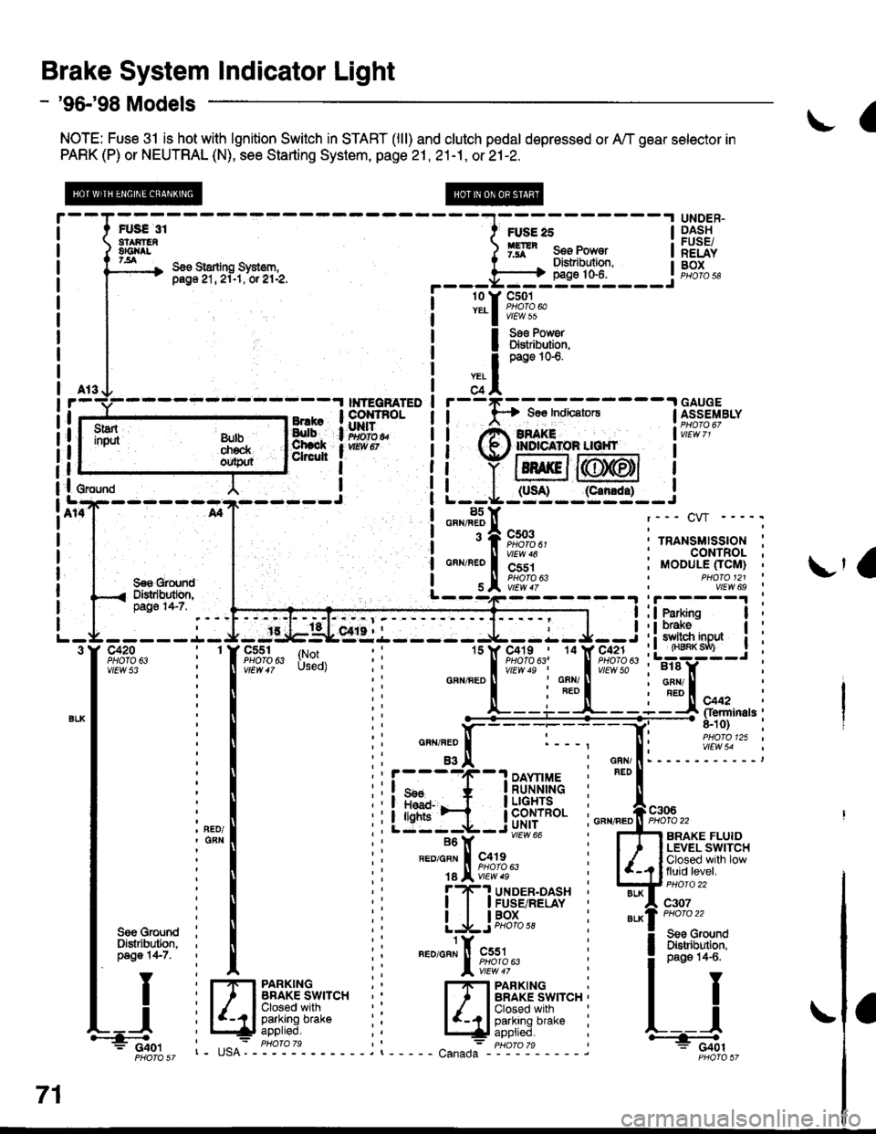
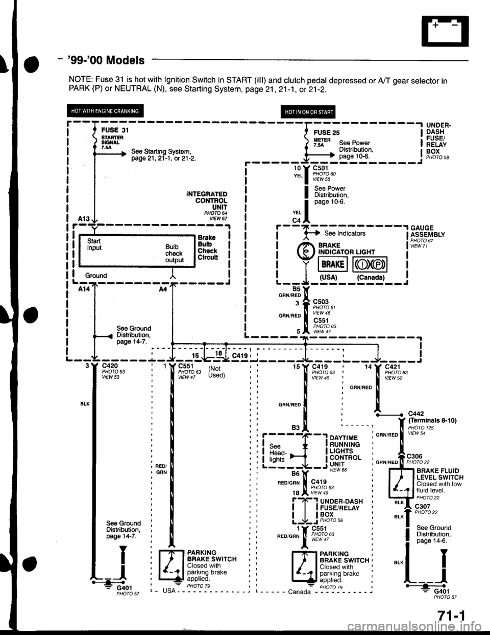
the driver that the parking brake is applied, or that
the brake fluid level is low. lt also comes on as a
bulb test when the engine is cranked.
Parking Brake
With the ignition switch in ON (ll) or START (lll),
voltage is applied through fuse 25 to the brake
system light. When you apply the parking brake, the
switch closes and provides a ground for the light.
The light then comes on to remind you that the
parking brake is applied.
Brake Fluid Level
With the ignition switch in ON (ll) or START (lll),
voltage is applied through fuse 25 to the brake
system light. lf the brake fluid level is low, the brake
fluid level switch closes, providing ground to the
circuit. The brake system light then comes on,
alerting the d verto a low brake fluid level in the
brake master cylinder. (Check brake pad wear
before you add fluid).
Bulb Check
With the ignition switch in START (lll) and clutch
pedal depressed or A'lT gear selector in PARK (P)
or NEUTRAL (N), voltage is applied through fuse 31
to the brake bulb check circuit. The brake bulb
check circuit closes, allowing current to flow through
the brake system light and bulb check circuit to
ground. The brake system light then comes on to
test the bulb.
Refer to the Service Manual (Section 23, Electrical)
for specific tests or troubleshooting procedures.
71-2
a
\fa
Page 1971 of 2189
How the Circuit Works
Seat Belt Warning
With the ignition switch in ON (ll) or START (lll),
battery voltage is applied to the seat belt reminder
light. When the seat belt is not buckled, the seat
belt reminder/key-on beeper circuit in the
integrated control unit senses ground through the
closed seat belt switch. The seat belt reminder light
comes on and stays on, and the beeper beeps for
6 seconds. The reminder light and beeper will stop
when the seat belt is buckled or the timer circuit
deactivates them.
lgnition Key Warning
Battery voltage is supplied at all times to the seat
belt reminder/key-on beeper circuit in the
integrated control unit. When you turn on the
ignition key switch the integrated control unit
senses ground. lf you open the driver's door, the
door switch closes, causing the beeper to sound
until the door is closed.
Refer to the Service Manual (Section 23, Electrical)
for specitic tests or troubleshootrng procedures.
73-1