1997 HONDA CIVIC Engine replacement
[x] Cancel search: Engine replacementPage 72 of 2189

ILubrication Points
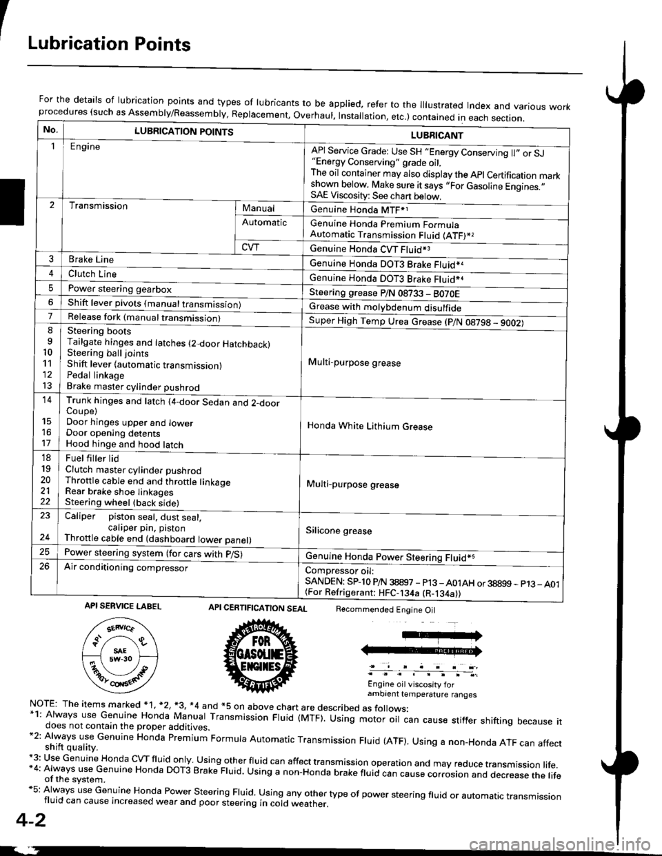
For the details of lubrication points and types of lubricants to be applied, refer to the lllustrated Index and various workprocedures (such as Assembly/Reassembly, Replacement, Overhaul. Installation, etc.) contained in each section.
No.LUBRICATION POINTS
Engine
LUBRICANT
"Energy Conserving" grade oil,The oil container may also display the Apl Certification markshown below. Make sure it says ,,For Gasoline Engines.,,SAE Viscosity: See chart below,
I
TransmissionManualGenuine Honda MTF*1
Genuine Honda Premium FormulaAutomatic Transmission Fluid (ATF)*,
Genuine Honda CVT Fluid*3
Genuine Honda DOT3 Brake Fluid*a
Automatic
CVT
3Brake Line
ClL,tci t""e4
I
Genuine Honda DOT3 Brake Fluid*aPower steering gearboxSteering grease P/N 08733 - BO70EShift lever pivots (manual transmission)Grease with molybdenum disulfide7-:ti
9
10'l'l
l3
14
't7
18
19
20
2122
Release fork (manual trancmi
Shift lever (automatic transmission)Pedal linkageBrake master cylinder pushrod
Super High Temp Urea crease (p/N 08798 - 9OO2)
i Multi-purpose grease
I
I
Honda White Lithium Grease
Multi-purpose grease
Silicone grease
@
Trunk hinges and latch (4-door Sedan and 2-doorCoupe)Door hinges upper and lowerDoor opening detentsHood hinge and hood latch-FUet T ter ttd
Clutch master cylinder pushrodThrottle cable end and throttle linkageRear brake shoe linkagesSteering wheel (back side)
23
E-
Caliper piston seal, dust seal,caliper pin. pistonThrottle cable end (dashboard lower panel)
Power steering system (for cars with p/S)
Air conditioning compressorComDressor oil:SANDEN: SPlo P/N 38897 - p13 -A01AH or 38899 - p13_ A01{For Refrigerant: HFC-134a (R-134a))
CERTIFICATION SEAL
ffi
NorE: The items m arked * 1, *2, +3, *4 and +5 on above chan are described as folows:*1: Always use Genuine Honda Manual Transmission Fluid (MTF). Using motor oil can cause stiffer shifting because itdoes not contain the proper additives.*2: Always use Genuine Honda premium Formula Automatic Transmission Fluid (ATF). Using a non-Honda ATF can affectshift quality.+3: Use Genuine Honda cVTfluid only usingotherfluid can affect tra nsmission operation and may reduce transmission life.*4: Always use Genuine Honda DoT3 Brake Fluid. Using a non-Honda brake fluid can cause corrosion and dec.ease the lifeof the svstem.*5: Always use Genuine Honda Power steering Fluid. using any other type of power steering fluid or automatrc transmissionfluid can cause increased wear and poor steering in cold weather.
4-2
Recommended Engine Oil
Engine oil viscosity forambrent temperature ranges
API SERVICE LABEL
Page 112 of 2189

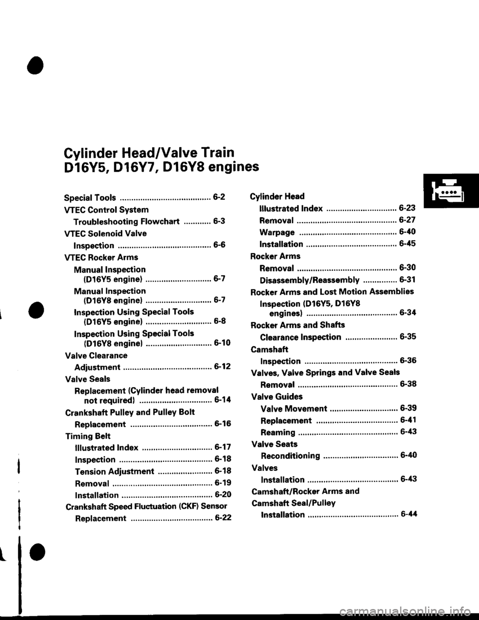
Cylinder Head/Valve Train
Dl6Y5, D16Y7, Dl6Y8 engines
Special Tools ............. G2
VTEC Control System
Troubleshooting Flowchart .........." 6-3
VTEG Solenoid Valve
Inspection ............" 6-6
VTEC Rocker Arms
Manual lnspection
(D16Y5 engine) ............................. 6-7
Manual Inspection
(D16Yg enginel ................'............ 6-7
Inspection Using Special Tools
{D16Y5 engine} .....................""'... 6-8
Inspection Using Special Tools
(D16Y8 engine) .........................'.'. 6-10
Valve Clearance
Adiustment ..."".....6-12
Valve Seals
Replacement (Cylinder head removal
not requiredl ................................ 6-1tl
Crankshaft Pulley and PulleY Bolt
Replacement ."...... &16
Timing Selt
lllustrated Index ............................... 6-17
Inspection .............. 6-18
Tension Adjustment ........................ 6- 1 I
Removal ......,,......... 6-19
lnstallation ............. 6-20
Crankshaft Speed Fluctuation (CKF) Sensor
Repf acement .........6'22
Cylinder Head
lllustrated Index ............................... 6-23
Removal ................. 6-27
Warpage ................ 6-40
lnstallation ............. 6-45
Rocker Arms
Removal ................. 6-30
Disassembly/Reassambly ............... 6-31
Rocker Arms and Lost Motion Assemblies
Inspection (D16Y5, D16Yg
enginesl "..........' 5-34
Rocker Arms and Shafts
Glearance Inspection ....................... 6-35
Camshaft
Inspection .............. 6-36
Valves, Valve Springs and Valve Seals
Removal ........""..... 6-38
Valve Guides
Valve Movement .............................. 6-39
Replacement .........6-41
Reaming .......'......'.' 6-43
Valve Seats
Reconditioning .'....6'40
Valves
lnstallation ............. 6-tt3
Camshaft/Rocker Arms and
Camshaft Seal/Pulley
lnstallation ............. 6-44
Page 128 of 2189

Timing Belt
Illustrated lndex
NOTE:
. Refer to page 6-20 for how to position the crankshaft and pulley before installing the belt.
. Mark the direction of rotation on the belt before removing.
a Do not use the upper cover and lower cover for storing removed items,
. Clean the upper cover and lower cover before installing.
. Replace the ca mshaft seals and cra n kshaft sea ls if there is oil leakage.
. Refer to page 6-16 before installing the timing belt.
CYLINDER HEADCOVERReler to page 6-46when installing.
HEAD COVEB GASKETReplaco when l6akin9,domaged or deteriorated.Apply liquid gasket at
th€ lour corners of thetecessos.
d
@
TIMING BELTInspection, page 6-18Adjustment, page 6-18Removal, page 6-19Installation. page 6-20
I x 1.25 mm3t N.m {3.8 kgf'm, 27 lbfftl
Apply engine oilto the bolt
thleads.
CRANKSHAFT SPEED FI.UCTUATION
lcr(Fl sENsoRReplacement, Page 6-22
UPPER COVEB
lnstallwithsurface facing in.
TIMING BELTDRIVE PULLEYReplacement, page 6_16
6x1.0mm9.8 N'm 11.0 kgt m,7.2 tbf.ft)NUBBER SEALSReplace when damagedor deledorated.
LOWER COVER
FUBBERPLUG
CRANKSHAFT PULLEYReplacement, page 6'16
PULLEY BOLTlil x 1.25 mm20 N.m 12.0 kgt.m,14 lbt'ft) + 90"Replacement, page 6'16Do not us6 an impactwrench when installing.
x 1.0 mmBOLT o-RING10 x 1,25 mm Reolace.14 N.m {,1.5 kgt m, 33 lbt ftl
6x1.0mmt2 N.m 11.2 kgf'm,8.7 tbt f0
9.E N'm (1.0 kgt.m,?.2 tbf.ftl\.-,o
6-17
Page 136 of 2189

D16Y5 engine:
I x 1.25 mm20 N.m (2,0 kgf m, 14 lbf ft)
Apply engine oilto the
threads.ROCKEB ARMASSEMBLYFemoval, page 6-30
Inspection, Page 6-34
6x1.0mm12 N.m 11.2 kgf m, 8.7 lbf'ftl
Apply engine oilto the
threads.
VALVE KCEPERS
SPRING RETAINER
CAMSHAFTInspection, page 6-36
6x1.0mm12 N,m 11.28.7 tbf.ft)
WEC SOLENOIDVALVEBINTAKE VALVESPRING
INTAKE VALVE SEAL
Replace.
VALVE SPRINGSEAT
INTAKE VALVEGUIDE
CAMSHAFTPUL|'IY
VTEC SOLENOIDVALVE FILTERReplace.
OIL CONTROLORIFICEClean.
VALVE
SPRING RETAINEB
EXHAUST V
SPRING
VE
EXHAUST VALVE
SEALt"o'""".uoau,
SEATReplace.
GUIDEInspection, page 6-39Replacement, Page 6-41
Reaming, page 6-43EXHAUSTVALVEOIL SEALReplace.
HEAD
8 x 1.25 mm
37 N.m 13.8 kgf.m,
27 tbf.frlApply engine oiltothe lhreads.
(cont'd)
6-25
INTAKE VALVERemoval, page 6 38
Installalion, Page 6 43Removal, page 6-27Warpage, Page 6 40
Valve seat reconditioning'page 6-40lnstallation, page 6_45
Page 137 of 2189

Cylinder Head
lllustrated Index (cont'dl
VALVE KEEPERS
SPRING RETAINER
INTAKE VALVE
VTEC SOLENOIDVALVE FILTEBReplace.
OIL CONTROLORIFICEClean.
INTAKE VALVE SEALReplace.VALVE SPRINGSEAT
INTAKE VAI.VEGUIOE
CAMSHAFTPULLEY
I
I
VALVE KEEPERS
SPRING RET
EXHAUST VALVESPRING
@
EXHAUST VALVESEALReplace.
8 x 1.25 mm37 N.m 13.8 kgt m,27 tbfitlApply engine oiltothe threads.
EXHAUSTVALVE
-vp
e,.io"o reassembring, crean at the parts in sorvent, dry them and appry rubricant to any contact parts.
D16Y8 engine:
LOST MOTIONASSEMgLY
ROCKER ARMASSEMBLYRemoval, page 6 30Inspection, page 6-34
5xl.0mm12 N.m {1.28.7 tbf.ft)
VALVE SPRINGSEATEXHAUSTVALVE O.RINGGUIDE Replace.Inspection, page 6 39Replacement, page 6 41Reaming, page 6 43
LOST MOTIONASSEMBLYHOLDER
INTAKE VALVEBemoval, page 6 38Installation, page 6 43
20 N.m 12.0 kgl.m, 14 tbf.ft)Apply engine oit to thethreads.
\
\
s9illl
CAMSHAFTInspection, page 6-36
OIL SEALBeplace.
CYLINDER HEADRemoval, page 6 27Warpage, page 6-40Valve seat reconditioning,page 6 40Installation, page 6-45
6x1.0mm12 N.m (1.2 kgt.m,8.7 lbf.ftlApply engine oil to thethreads,
Page 153 of 2189

Valve Guides
Replacement (cont'd)
Working from the camshaft side, use the driver andan air hammer to drive the guide about 2 mm (0.1 in)towards the combustion chamber. This will knock offsome of the carbon and make removal easier.
CAUTION:
. Always wear satety goggles or a face shield when
driving valve guides.
. Hold the air hammer directly in line with thevalve guide to prevent damaging the driver.
Turn the head over, and drive the guide out towardthe camshaft side of the head.
VALVE GUIOE ORIVER,5.5 mm07742 - 001 01 00
It a valve guide still won't move, drill it out with a8 mm {5/16 in) bit, then try again.
CAUTION: Drill guides only in extreme cases; you
could damage the cylinder head it the guide breaks.
6. Remove the new guides from the freezer, one at atime, as you need them.
6-42
I7. Apply a thin coat of clean engine oil to the outsideof the new valve guide. Install the guide from thecamshaft side of the head; use the special tool todrive the guide in to the specified insralled height. lfyou have all 16 guides to do, you may have to reheat
the head.
VALVE GUIOEDRIVER,5.5 mm07742 - 0010100
ll
Valve Guide lnstalled Height:
Intake: 17.85 - 18.35 mm (0.703 - 0.722 inl
Exhausi: 18.65 - 19.15 mm (0.734 - 0.754 in)
VALVE GUIDE
Page 159 of 2189

Gylinder Head/Valve Train
816A2 engine
Special Tools ............. 6'50 Rocker Arms
VTEC Contlol System
Troubfeshooting Flowchart ............ 6-51 Disassembly/Reassembly ...............6'72
VTEC Solenoid ValveRocker Arms and Lost Motion Assemblies
Inspection ...""'...... 5-54 Inspection .........""' 6-73
VTEC Rocker ArmsRocker Arms and Shafts
Manual Inspection ........................... 6-54 Clearance Inspection ..'..."'.............. 6-74
Inspection Using Special Tools .....' 6-55 Camshafts
Valve Clearance
.^ Adiustment .........." 6-57 Valves'Valve Springs and Valve Seals
. t Crankshaft Pulley and Pulley Bolt Removal """"""""' 6-77
Replacement ..".....6-59 Valve Seats
Timing BeltReconditioning ......6'78
Cylinder Headlnstallation '............ 6-82
Page 203 of 2189

lllustrated Index
(cont'd)
NOTE: New rod bearings must be selected by matching connecting rod assembly and crankshaft(see page 7,11).identification markings
Lubricate all internal parts with engine oil duringreassembtv.
PISTON INSTALLATION DIRECTION:
EXHAUST
4\/=\6\z\
\e/!rqrf/
INTAKE
PISTON RINGSReplacement. page 7-20Measurement, pages 7 20 andj-21Alignment, page 7-21
PISTON PINRemoval, page 7,17Installation, page 7-18Inspection, page 7,19
CONNECTING RODEnd play, page 7-8Selection, page 7,18
CONNECTING RODBEARINGSClearance, page 7 11Selection, page 7-11
CONNECTING ROD BEARING CAPInstallation, page 7-23NOTE: lnstall caps so thebearing recess is on thesame side as the recessin the rod.
PISTONInspectron, page 7-15NOTE: Betore removing the piston, inspect thetop of the cylinder bore for carbon build-up orridge. Bemove ridge if necessary, page 7-13
ENGINE BLOCKCylinder bore inspection, page 7-16Warpage inspection, page 7,'16Cylinder bore honing, page 7,17
Inspect top of each cylinder borefor carbon build-up or ridgebefore removing piston.Remove ridge if necessary, page 7-13
CONNECTING ROD CAP NUT816A2 €ngin6:9 x 0.75 mm{0 N.m (4.1 kgt m, 30 tbf.ftlD16Y5, Dl6Y7. D16Y8 engines:8 x 0.75 mm3l N.m {3.2 kg{.m,23 tbt.fr)Apply engine oiltothe bolt threads.NOTE: After torquing each bearingcap, rotate crankshaft tocheck for binding.
7-6