1997 HONDA CIVIC Brake pipes
[x] Cancel search: Brake pipesPage 61 of 2189

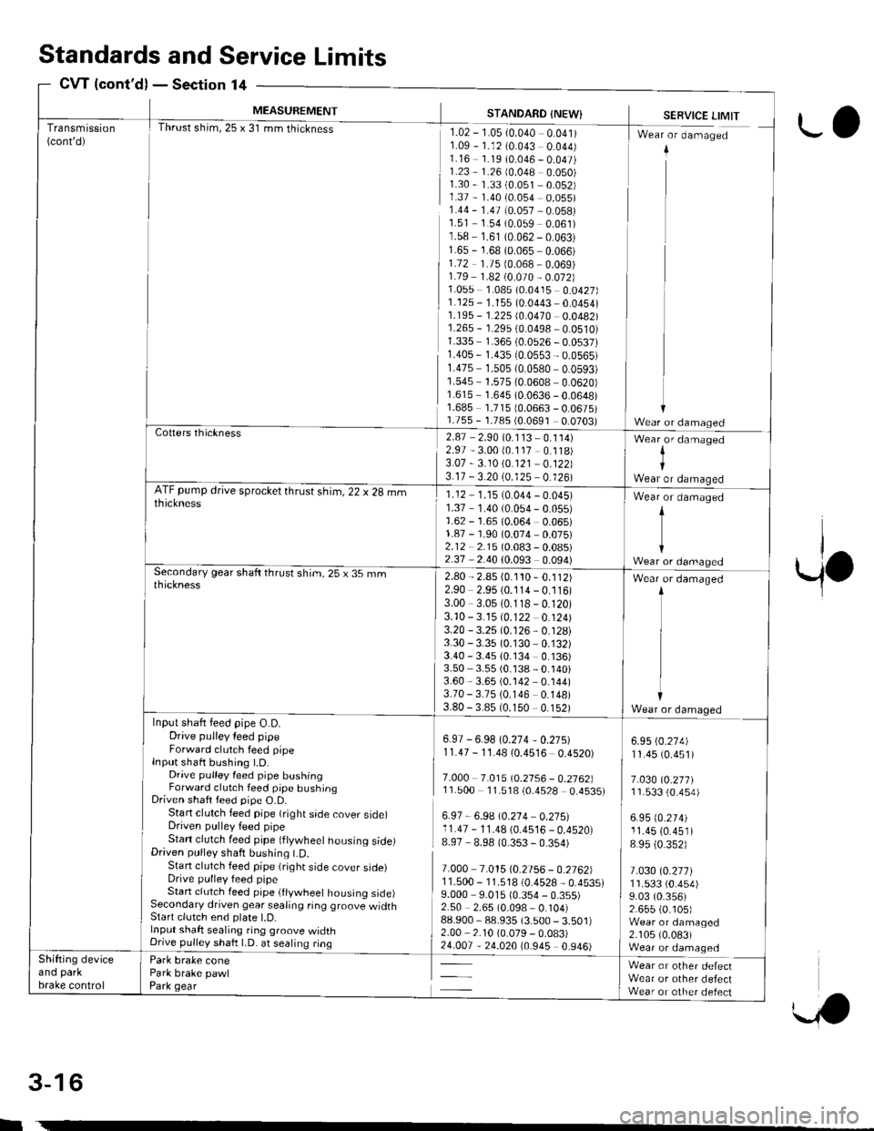
Transmission(cont'd)
MEASUREMENT
Thrust shim,25 x 31 mm thickness
STANDARD {NEW}
rlz-r-osr-o.o+o oolrr1.09 - 1.12 (0.043 0.044)1.16 1.19 (0.046 - 0.047)1.23 1.26 (0.048 0.050)1.30 - 1.33 (0.051 0.052)1.37 - 1.40 (0.054 0.055)1.44 - 1.47 (0.057 0.058)1.51 1.54 (0.059 0.061)1.58 1.61 (0.062 - 0.063)1.65 - 1.68 (0.065 0.066)1.72 1.75 {0.068 0.069)1.79 1 .a2 t0.O10 - 0.012]}1.055 1.085 (0.0415 0.0427)1.125 - 1.155 (0.0443 0.0454)1.195 - '�I.225 (0.0470 0.0482)1.265 - 1.29s (0.0498 0.0510)1.335 1.365 (0.0526 - 0.0537)1.40s - 1.435 (0.0553 - 0.0565)r.475 1.505 {0.0580 0.0593)1.545 1.575 (0.0608 0.0620)1.615 1.645 (0.0636 - 0.0648)1.685 1.71510.0663 - 0.0675)1.755 - 1.785 {0.0691 0.0703)
SERVICE LIMIT
I Wr"r - d-"-"g"d
ii
11
ir
Cotters thickness2.87 - 2.90 (0.1 13 - 0.114)2.97 - 3.00 (0.117 0.118)3.07 -3.10 \0.121 0.122)3.17 - 3.20 (0.125 0.126)
Wear,or damaged
IWear or damaoedATF pump drive sprocket thrust shim, 22 x 28 mmthickness1.12 1.1510.044 - 0.045)1.37 1.40 (0.054 - 0.055)1.62 - 1.65 (0.064 0.065)1.87 - 1.90 (0.074,0.075)2.12 2.15 (0.083 - 0.08s)2.37 2.40 (0.093 0.094)
Wear or damaged
t
{Wear or damagedSecondary gear shaft thrust shim, 25 x 35 rnmthickness2.80 - 2.85 (0.1'�t0 - 0.112)2.90 2.95 (0.114 - 0.116)3.00 3.05 (0.118 - 0.120)3.10 -3.15 10.122 0.124)3.20 - 3.25 (0.126, 0.128i3.30 - 3.35 (0.130 0.132)3.40 - 3.4s 10.134 0.136)3.50 3.55 (0.138 - 0.140)3.60,3.65 (0.142 0.144)3.70 - 3.75 (0.146 0.148)3.80 - 3.8510.150 0.152)
Wear or damaged
Wear or damaqedInput shaft feed pipe O.D.Drive pulley leed pipeForward clutch feed pipeInput shaft bushing t.D.Drive pulley feed pipe bushingForward clutch feed pipe bushingDriven shaft feed pipe O.D.Start clutch feed pipe (right side cover side)Driven pulley feed pipeStan clutch feed pipe (ftywheet housing side)Driven pulley shaft bushing LD.Stan clutch feed pipe (right side cover sroerDrive pulley feed pipeStart clutch feed pipe (flywheel housing side)Secondary driven gear sealing ring groove widthStart clutch end plate l.D.Input shaft sealing ring groove widthDnve pullev shaft LD. at sealing ring
Park brake conePark brake pawlPark gear
6.97 - 6.98 (0.274 - 0.27s)11.47 - 1'1.48 (0.4516 0.4520)
7.O0O 7.0t510.2156 - 0.2762]l11.500 11.518 (0.4528 0.4535)
6.97 - 6.9A \0.214 0.275:l11.47 - 11.48 (0.4516 _ 0.4520)8.97 8.98 10.353 - 0.354)
7.000 7.015 (0.2756 - 0.2762)1 1.500 - '11.518 (0.4528 - 0.4535)9.000 9.015 10.354 - 0.355)2.50 2.65 (0.098 0.104)88.900,88.935 (3.500 - 3.501)2.00 2.10 10.079 - 0.083)
5*
6.95 (0.274)
11.45 (0.451)
7.030 (0.277)11.533 (0.4s4)
6.95 (0.274)
11.45 (0.451)
8 95 (0.352)
t.030l0.2t7l1r.533 (0.454)
9.03 (0.356)2.655 (0. r05)Wear or damaged2.105 (0.083)Wear or damaqedShifting deviceano parKbrake control
Wear or other defectWear or other defectWear or other defect
Standardsand Service Limits
CW {cont'd)Section 14
rl
w
3-16
ro
Page 873 of 2189

Description
The Continuously Variable Transmission (CVT) is an electronically controlled automatic transmission with drive and driv
en Oullevs, and a steel belt. The CVT provides non stage speeds forward and one reverse. The entire unit is positioned in
line with the engine.
Transmission
Around the outside of the flywheel is a ring gear which meshes with the starter pinion when the engine is being staned.
The transmission has four parallel shafts: the input shaft, the drive pulley shaft. the driven pulley shaft, and the secondary
gear shaft. The input shaft is in line with the engine crankshaft. The drive pulley shaft and the driven pulley shaft consist of
movable and fixed face pulleys. Both pulleys are linked by the steel belt.
The input shaft includes the sun gear. The drive pulley shaft includes the forward clutch which mounts the carrier assem-
bly on the forward clutch drum. The carrier assembly includes the pinion gears which mesh with the sun gear and the ring
gear. The ring gear has a hub-mounted reverse brake disc.
The driven pulley shaft includes the start clutch and the secondary drive gear which is integral with the park gear' The sec-
ondary gear shaft is positioned between the secondary drive gear and the final driven gear. The secondary gear shaft
includes the secondary driven gear which serves to change the rotation direction. because the drive pulley shaft and the
driven oullev shaft rotate the same direction. When certain combinations of planetary gears in the transmission are
engaged by the clutches and the reverse brake, power is transmitted from the drive pulley shaft to the driven pulley shaft
to provide E, E, E, and El.
Electronic Control'96 - 98 Models:
The electronic control system consists of the Transmission Control Module (TCM), sensors, three linear solenoids, and a
inhibitor solenoid. Shifting is electronically controlled under all conditions'
The TCM is located below the dashboard, behind the kick panel on the driver's side.'99 - 00 Models:
The electronic control svstem consists of a Powertrain Control Module (PCM), sensors, three linear solenoids and an
inhibitor solenoid. Shifting is electronically controlled under all conditions. A Grade Logic Control System to control shift-
ing in E position while the vehicle is ascending or descending a slope.
The PCM is located below the dashboard, under the kick panel on the passenger's side.
Hydraulic Control
The lower valve body assembly includes the main valve body, the Pressure Low (PL) reguiator valve body, the shift valve
body, the start clutch control valve body, and the secondary valve body. They are positioned on the lower part of the
transmission housing.
The main valve body contains the Pressure High (PH) control valve, the lubrication valve, and the pitot regulator valve.
The secondary valve body contains the PH regulator valve, the clutch reducing valve, the start clutch valve accumulator,
and the shift inhibitor valve. The PL regulator valve body contains the PL regulator valve and the PH-PL control valve
which is ioined to the PH,PL control linear solenoid. The inhibitor solenoid valve is bolted on the PL regulator valve body.
The shift valve body contains the shift valve and the shift control valve. which is joined to the shift control linear solenoid.
The start clutch control valve body contains the start clutch control valve, which is joined to the start clutch control linear
solenoid. The linear solenoids and the inhibitor solenoid are controlled by the TCM or PCM. The manual valve body which
contains the manual valve and the reverse inhibitor valve, is bolted on the intermediate housing.
The ATF pump assembly is located on the transmission housing, and is linked with the input shaft by the sprockets and
the sprocket chain. The pulleys and the clutch receive fluid from their respective feed pipes, and the reverse brake receives
fluid from internal hydraulic circuit.
Shift Control Mechanism
Input from various sensors located throughout the vehicle determines which linear solenoid the TCM or PCM will activate.
Activating the shift control linear solenoid changes the shift control valve pressure, causing the shift valve to move. This
pressurizes the drive pulley pressure to the drive pulley and the driven pulley pressure to the driven pulley and changes
their effective pulley ratio. Activating the start clutch control linear solenoid moves the start clutch control valve. The start
clutch control valve uncovers the port, providing pressure to the start clutch to engage it(cont'd)
14-195
,!
Page 876 of 2189

Description
Clutches/Reverse Brake/Planetary Gear/Pulleys
Clulches/Reverse Brake
The CVT uses the hydraulically-actuated clutches and brake to engage or disengage the transmission gears. When
hydraulic pressure is introduced into the clutch drum and the reverse brake piston cavity, the clutch piston and the reverse
brake piston move. This presses the friction djscs and the steel plates together, locking them so they don't slip. Power is
then transmitted through the engaged clutch pack to its hub-mounted gear. and through engaged ring gear to pinion
gears.
Likewise, when the hydraulic pressure is bled from the clutch pack and the reverse brake piston cavity, the piston releases
the friction discs and the steel plates, and they are free to slide past each. This allows the gear to spin independently on its
shaft, transmitting no power.
Start Clutch
The start clutch, which is located at the end of the driven pulley shaft, engages/disengages the secondary drive gear.
The start clutch is supplied hydraulic pressure by its ATF feed pipes within the driven pulley shaft.
Forward Clutch
The forward clutch, which is located at the end of the drive pulley shaft, engages/disengages the sun gear.
The forward clutch is supplied hydraulic pressure by its ATF feed pipe within the drive pulley shaft.
Reverse Brake
The reverse brake, which is located inside the inte.mediate housing around the ring gear, locks the ring gear in E posi-
tion. The reverse brake discs are mounted to the ring gear and the reverse brake plates are mounted to the intermediate
housing. The reverse brake is supplied hydraulic pressure by a circuit connected to the internal hydraulic circuit.
Planetary Gear
The planetary gear consists of a sun gear, a carrier assembly, and a ring gear. The sun gear is connected to the input shaft
with splines. The pinion gears are mounted to the carrier which is mounted to the fo.ward clutch drum. The sun gear
inputs the engine power via the input shaft to the planetary gear, and the carrier outputs the engine power. The ring gear
is only used for switching the rotation direction of the pullev shafts,
In E. E, and E positions (forward range), the pinion gears don't rotate and revolve with the sun gear, so the carrier
rotates. In E] positjon {reverse range), the reverse brake locks the ring gear and the sun gear drives the pinion gears to
rotate. The pinion gears rotate and revolve in the opposite direction from the rotation direction of the sun gear, and the
carrier rotates with pinion gear revolution.
Pulleys
Each pulley consists of a movable face and a fixed face, and the effective pulley .atio changes with engine speed. The
drive pulley and the driven pulley are linked by the steel belt.
To achieve a low pulley ratio, high hydraulic pressure works on the movable face of the driven pulley and reduces the
effective diameter of the drive pulley. and a lower hydraulic pressure works on the movable face of the drive pulley to
eliminate the steel belt slippage. To achieve a high pulley ratio, high hydraulic pressure works on the movable face of the
drive pulley and reduces the eifective diameter of the driven pulley, and a lower hydraulic pressure works on the movable
face of the driven pulley to eliminate the steel belt slippage.
b
14-198
Page 1014 of 2189

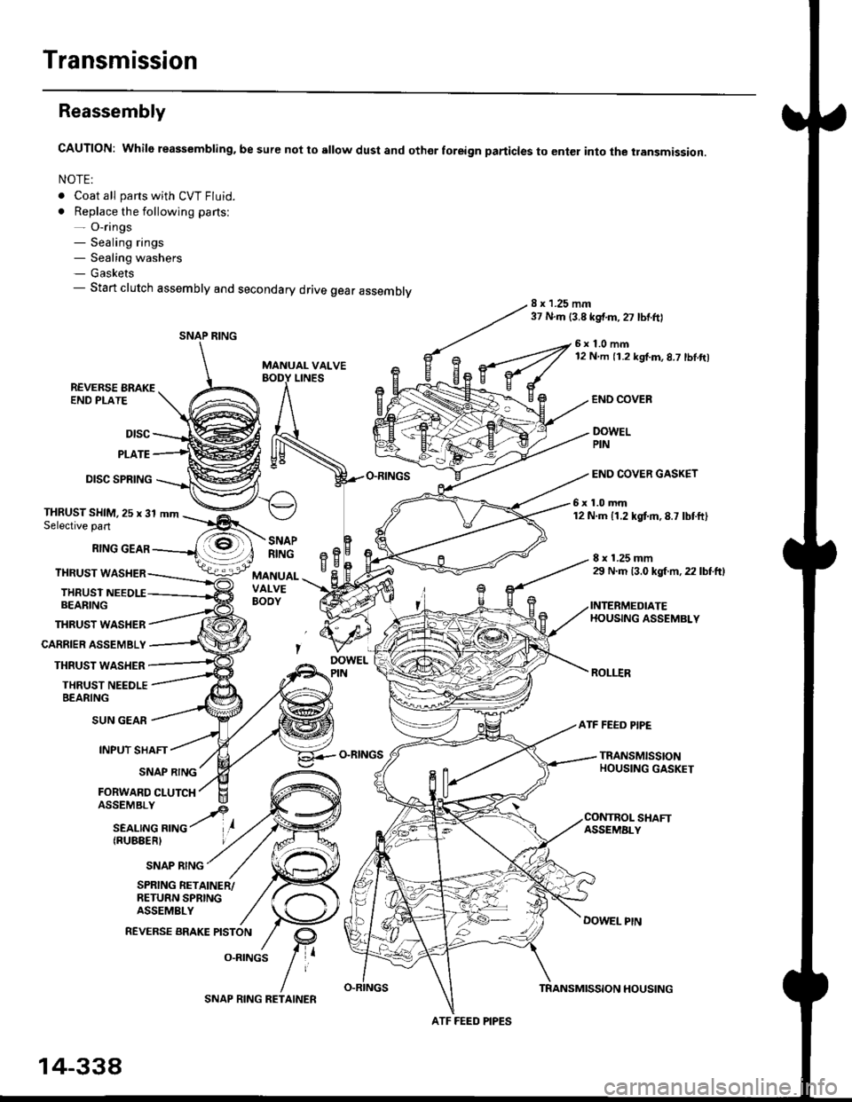
Transmission
Reassembly
CAUTION: While reassembling. be sure not to sllow dust and othor foreign particles to enter into the transmission.
NOTE:
. Coat all parts with CVT Fluid.
. Replace the following parts:- O-rings- Sealing rings- Sealing washers- Gaskets- Start clutch assembly and secondary drive gear assembly8 x 1.25 mm37 N.m {3.8 kgf.m,27 lbtftl
MANUAL VALVE
6x1.0mm12 N m 11.2 kgf.m,8.7 lbl.ft)
LINESREVERSE BRAKEEND PLATE
Dtsc
PLATE
DISC SPRING
THRUST WASHER
CARRIER ASSEMBLY
THRUST WASHER
THRUST NEEDLEBEARING
END COVEB
DOWELPIN
END COVER GASKET
6x1.0mm12 N.m 11.2 kgtm,8.7 lbtft)THRUST SHIM,25 x 31 mmSelective part
RING GEAR
THRUST WASHER
THRUSTBEARING
8 x 1.25 mm29 N.m 13.0 kgl m, 22 lbtftl
INTERMEDIATEHOUSING ASSEMBLY
ROLI.IR
SNAPRINGeBH^cMANUALVALVEBOOY
SUN GEAR
INPUT SHAFT
(RUBEERI
ATF FEED PIPE
O-RINGSTRANSMISSIONHOUSING GASKETSNAP RING
FORWARD CLUTCH
SNAP RING
SHAFTASSEMALY
DOWEL PtN
SPRING RETAINER/RETURN SPRINGASSEMBLY
REVERSE BRAKE PISTON
O.RINGS
SNAP RING
ATF FEED PIPES
14-338
SNAP RING RETAINERTRANSMISSION HOUSING
Page 1015 of 2189

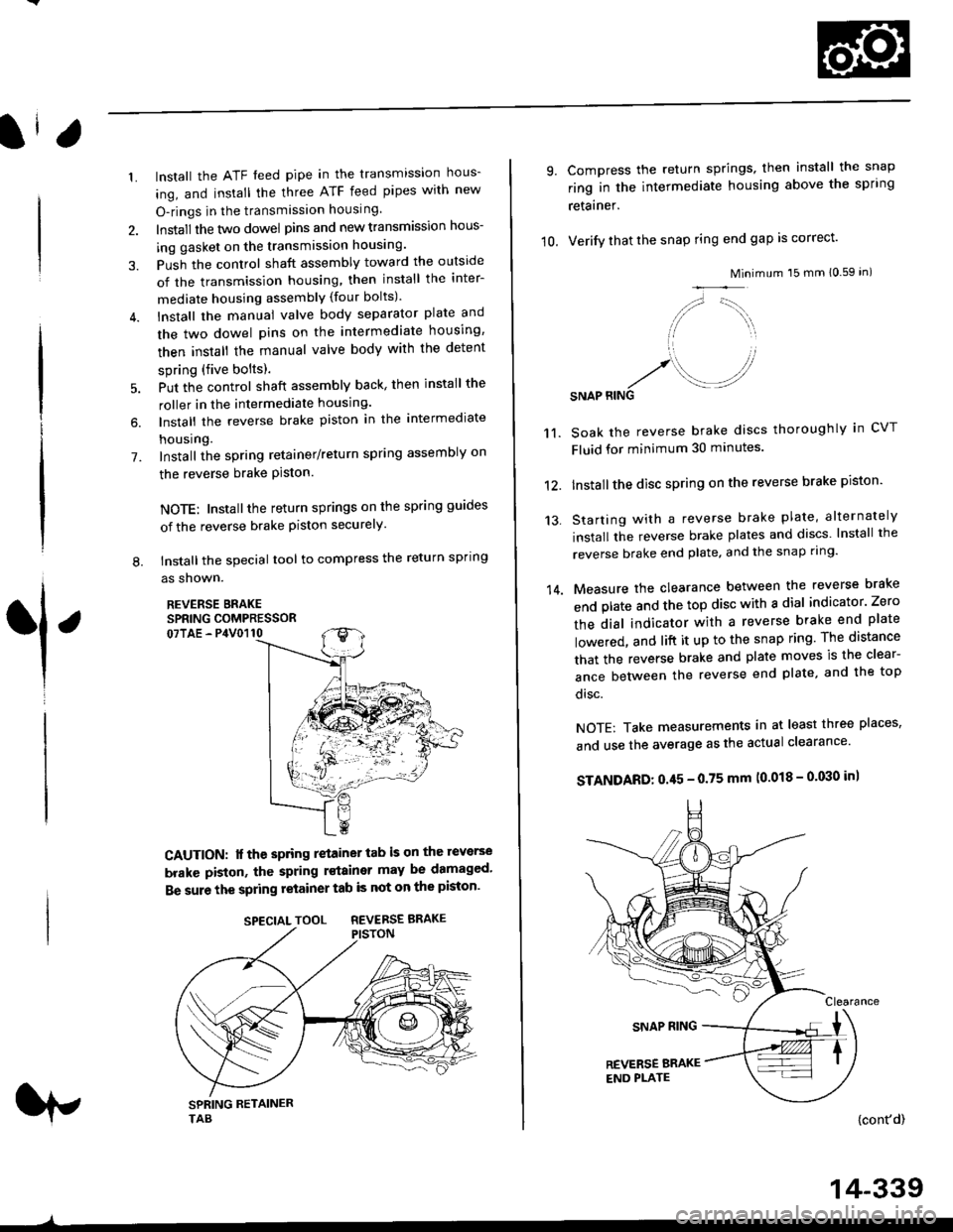
1.
7.
lnstall the ATF feed pipe in the transmission hous-
ing, and install the three ATF feed pipes with new
O-rings in the transmission housing,
Install the two dowel pins and new transmission hous-
ing gasket on the transmission housing.
Push the control shaft assembly toward the outside
of the transmission housing, then install the inter-
mediate housing assembly (four bolts).
lnstall the manual valve body separator plate and
the two dowel pins on the intermediate housing,
then install the rnanual valve body with the detent
spring (five bolts).
Put the control shaft assembly back, then install the
roller in the intermediate housing.
lnstall the reverse brake piston in the intermediate
housing.
Install the spring retainer/return spring assembly on
the reverse brake Piston.
NOTE: Installthe return springs on the spring guides
of the reverse brake piston securely
tnstall the special tool to compress the return spring
as shown.
REVERSE BRAKESPRING COMPRESSOR07TAE - P4V0110
6.
L
1
CAUTION: lf the spring retainer tab is on the reverse
brakc piston, the spring rstainer may be damaged'
Be sure the spring retainer tab is not on the piston'
rp
SPECIALTOOL REVERSEBRAKE
-^
14-339
10.
9.
14.
Compress the return springs, then install the snap
ring in the intermediate housing above the spring
retainer.
Verify that the snap ring end gap is correct'
Mini
/,,- '-t,,,,.
// \i/ ',r
'1 ,
.r' //'/. .-J?RINGSNAP
mum 15 mm 10.59 in)
Soak the reverse brake discs thoroughly in CVT
Fluid for minimum 30 minutes.
Installthe disc spring on the reverse brake piston'
Starting with a reverse brake plate, alternately
install the reverse brake plates and discs lnstall the
reverse brake end plate, and the snap ring'
Measure the clearance between the reverse brake
end plate and the top disc with a dial indicator' Zero
the dial indicator with a reverse brake end plate
lowered, and lift it up to the snap ring The distance
that the reverse brake and plate moves is the clear-
ance between the reverse end plate, and the top
disc.
NOTE: Take measurements in at least three places'
and use the average as the actual clearance'
STANDARD: 0.45 - 0.75 mm (0.018 - 0'030 in)
{cont'd)
11.
12.
13.