Page 1373 of 2189
Emblem
Installation
Apply the emblem where shown.
NOTE:
. Before applying, clean the body surface with a sponge dampened in alcohol.. After cleaning, keep oil, grease and water from getting on the surface.
Attachment Point (ReferencG):Unit: mm (in,)
CIVIC EMBLEM
Special EMBLEM
20-144
3D: Special emblem {for Canada Sosciel Editionl
Page 1375 of 2189
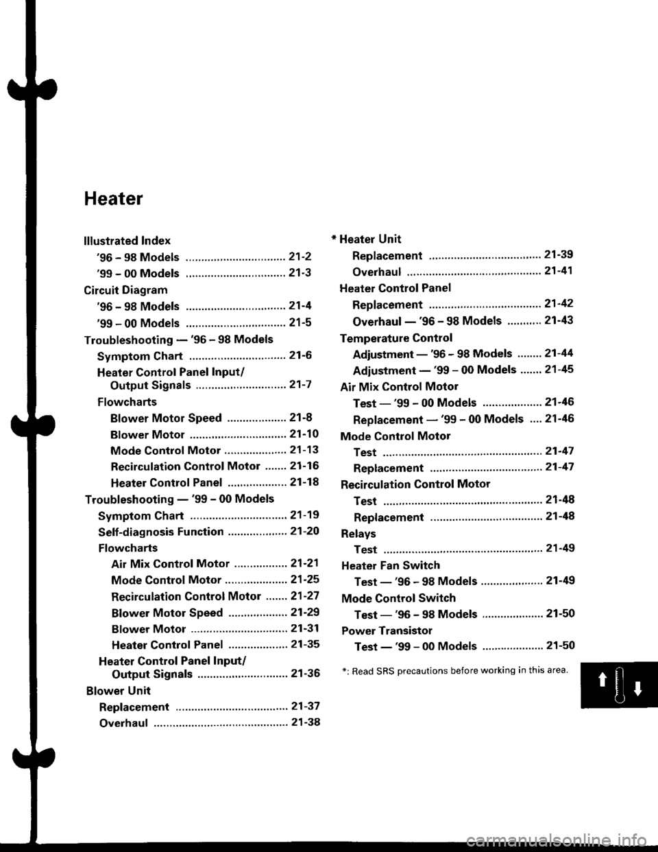
Heater
lllustrated Index
'96 - 98 Models ................................ 21'2
'99 - 00 Models ................................ 21'3
Circuit Diagram
'96 - 98 Models .....21-4
'99 - 00 Models ................................ 21-5
Troubleshooting - '96 - 98 Models
Symptom Chart ............................... 21-6
Heater Control Panel Input/
Output Signals ..............,.............. 21-7
Flowcharts
Blower Motor Speed ................... 21-8
Bf ower Motor ,...21'10
Mode Control Motor ............... ,.'.' 21-13
Recirculation control Motor ....... 21-16
Heater Control Panel ................ ... 21 -14
Troubleshooting - '99 - 00 Models
Symptom Chart ............................... 21-19
Seff-diagnosis Function ............,,,.... 21-20
Flowcharts
Air Mix Control Motor ......,.......... 21-21
Mode Control Motor ............... ..... 21 -25
Recirculation Control Motor ....... 21-27
Bf ower Motor Speed .............. .....21'29
Bf ower Motor ....21-31
Heater Control Panel ................,.. 21-35
Heater Control Panel Input/
Output Signals ............................. 21-36
Blower Unit
Repf acement .........21-37
Overhaul ................ 21-38
* Heater Unit
Replacement ....'....21-39
overhaul """" """' 21-4'l
Heater Control Panel
Repfacement .........21'42
Overhaul -'96 - 98 Models ........... 21-43
Temperature Control
Adjustment - '96 - 98 Models """" 21-44
Adiustment - '99 - 00 Models .......21-45
Air Mix Control Motor
Test - '99 - 00 Models ...........' .......21'46
Replacement - '99 - 00 Models ....21'46
Mode Control Motol
Test ................, .,...'.21'47
Replacement '.'."...21-47
Recirculation Control Motor
Test ................. .......21-48
Repf acement ......." 21-48
Relays
Test ................. .......2'l-49
Heater Fan Switch
Test - '96 - 98 Models ............. .......21-49
Mode Control Switch
Test -'96 - 98 Models ..........."....... 21-50
Power Transistor
Test - '99 - 00 Models ....'........ ....".21-50
*: Read SRS Drecautions before working in this area.
Page 1425 of 2189
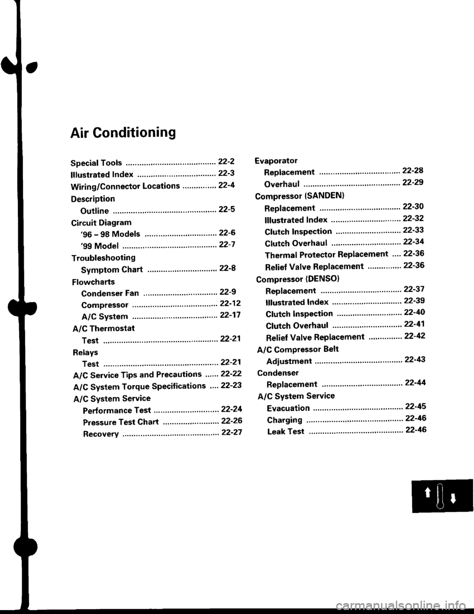
Air Conditioning
Speciaf Tools ......'.....' 22-2
f f f ustrated f ndex ......................... ".......' 22-3
Wiring/Connector Locations'.........'.... 22'4
Description
Outfine ............ .......22-s
Circuit Diagram
'96 - 98 Models ......"..........".......'.... 22-6
'99 Modef """""""' 22-7
Troubleshooting
Symptom Chart ".'......""................. 22-8
Flowcharts
Condenser Fan .........".................,..'. 22-9
Compressor .....""" 22-12
A/C System .........'.22'17
A/C Thermostat
Test ........'.......' """'22'21
Relays
Test ....."'......... ..""'22-21
A/C Service Tips and Precautions ......22-22
A/C System Torque Specifications '...22-23
A/C System Service
Performance Test ... '."......... ".... ....'..22-24
Pressure Test Chart .................. .... "' 22-26
Recovery ...".........," 22-27
Evaporator
Replacement .....",' 22'24
Overhauf .....-.....""' 22'29
Compressor {SANDEN}
Repf acement ......'.' 22-30
fffustrated fndex ......"..................'.... 22'32
Cf utch Inspection ......... "............ ...... 22-33
Clutch Overhau I ........................ ....... 22-34
Thermal Protector Replacement .... 22-36
Relief Valve Replacement ......'..."". 22-36
Compressor (DENSO)
Repfacement ..""',' 22-37
lf lustrated Index ............................... 22-39
Clutch lnspection ............."'...... "'.... 22-40
Cf utch Overhaul .....................'......... 22-41
Ref ief Valve Replacement'..'......"'.. 22-42
A/C Compressor Belt
Adiustment ............22'43
Condenser
Repfacement .......,,22'44
A/C System Service
Evacuation ...,,,.......22-45
Charging '..........--'..22'46
Leak rest """""""'22-46
Page 1459 of 2189
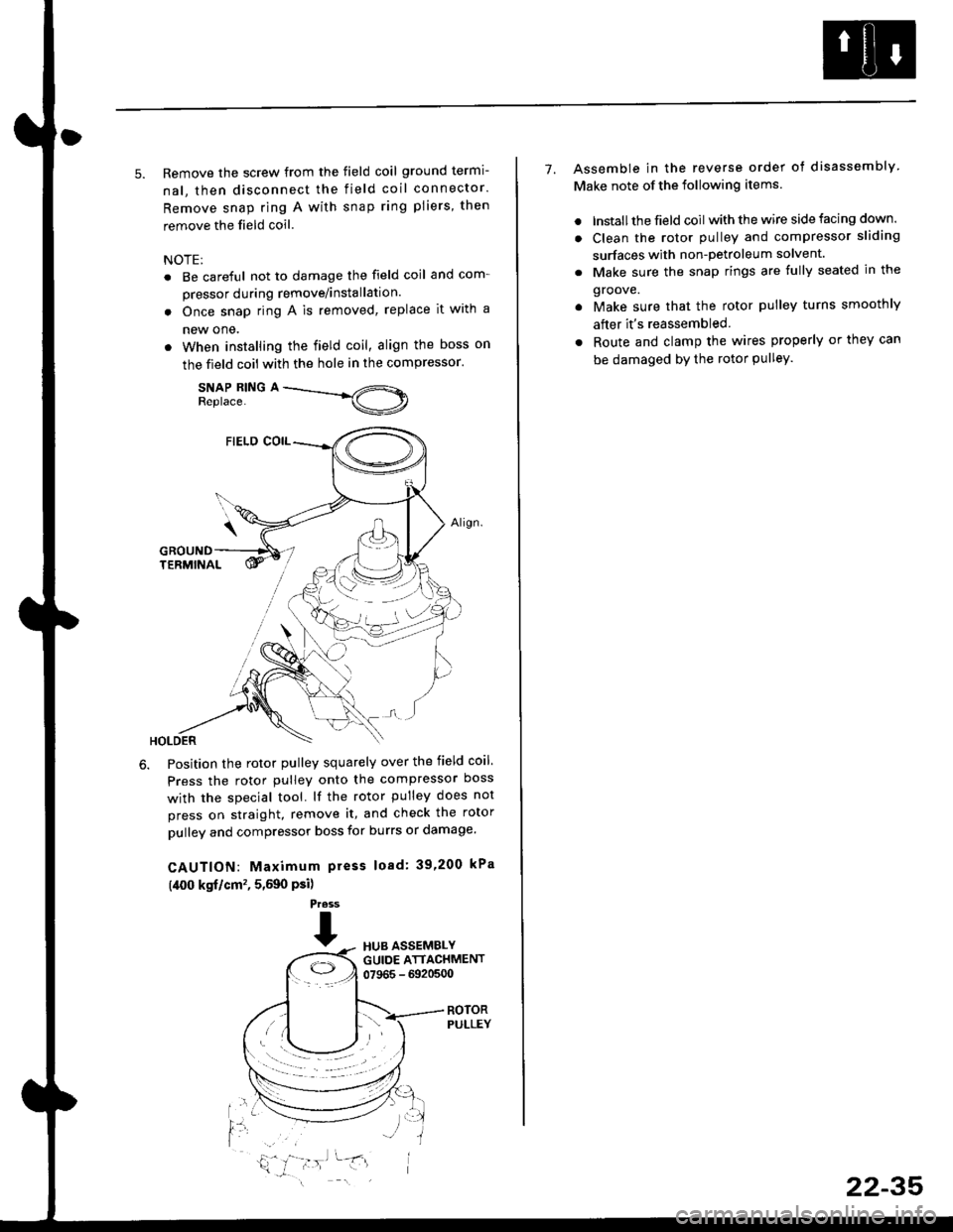
5. Remove the screw from the field coil ground termi-
nal, then disconnect the field coil connector.
Remove snap ring A with snap ring pliers, then
remove the field coil
NOTE:
. Be careful not to damage the field coil and com-
pressor during remove/installation.
. Once snap ring A is removed, replace it with a
new one.
. When installing the field coil, align the boss on
the field coil with the hole in the compressor.
SNAP RING AReplace.
Position the rotor pulley squarely over the field coil.
Press the rotor pulley onto the compressor boss
with the special tool. lf the rotor pulley does not
press on straight, remove it, and check the rotor
pulley and compressor boss for burrs or damage.
CAUTION: Maximum press load: 39,200 kPa
(,[00 kgf/cm'�, 5,590 Psi)
Press
THUB ASSEMBLYGUIDE ATTACHMENT07965 - 6920500
ROTORPULLEY
t'l
i,'
7. Assemble in the reverse order of disassembly
Make note of the following items.
. lnstall the field coil with the wire side facing down.
. Clean the rotor pulley and compressor sliding
surfaces with non-petroleum solvent.
. Make sure the snap rings are fully seated in the
groove.
. Make sure that the rotor pulley turns smoothly
after it's reassembled
. Route and clamp the wires properly or they can
be damaged bY the rotor Pulley.
22-35
Page 1460 of 2189
Compressor (SANDENI
Thermal Protestor Replacement
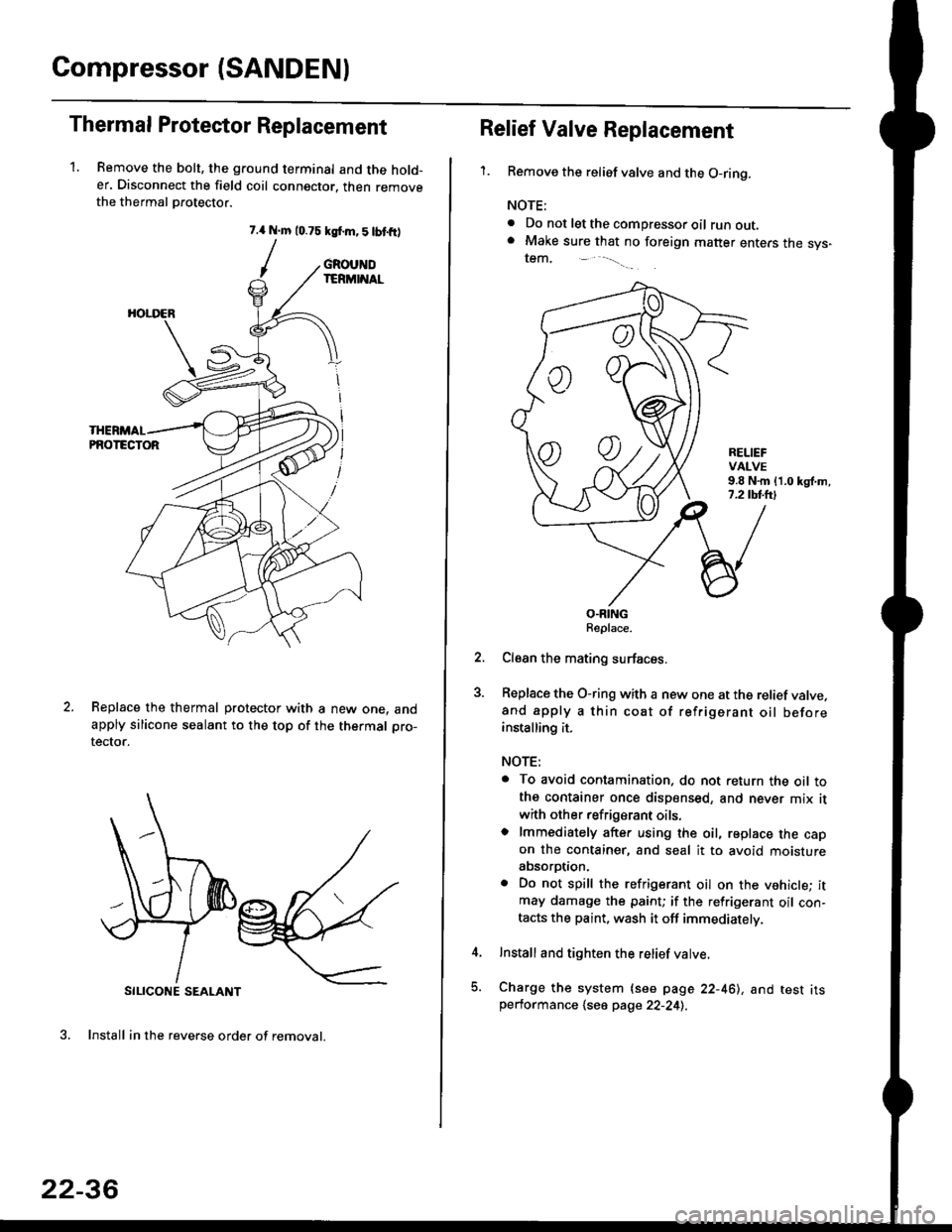
1. Remove the bolt, the ground terminal and the hold-er. Disconnect the field coil connector. then removethe thermal Drotector.
7.{ N.m 10.75 ksf.m,5lbtfr)
/
SILICONE SEALANT
3. Install in the reverse order of removal.
GROUNDIERMINAL
HOI.I'ER
PNOTECTOR
Replace the thermal protector with a new one. andapply silicone sealant to the top of the thermal pro-
tector.
22-36
oo
Relief Valve Replacement
'1.Remove the relief valve and the O-ring.
NOTE:
. Do not let the compressor oil runout.. Make sure that no foreign matter enters the sys-tem,
RELIEFVALVE9.8 N.m {1.0 kgl.m,7.2 tbl.lrl
O.RINGReplace.
Clean the mating surfaces.
Replace the O-ring with a new one at the relief valve.and apply a thin coat of refrigerant oil beforeinstalling it.
NOTE:
. To avoid contamination. do not return the oil tothe container once dispensed, and never mix it
with other refrigerant oils.o lmmediately after using the oil, replace the capon the container, and seal it to avoid moistureabsorption.
. Do not spill the refrigerant oil on the vehicle; itmay damage the paint; if the refrigerant oil con-tacts the paint, wash it off immediately.
Install and tighten the relief valve.
Charge the system {see page 22-461, and test itsperformance 1se6 page 22-241.
Page 1466 of 2189
Compressor (DENSO)
Clutch Overhaul (cont'd)
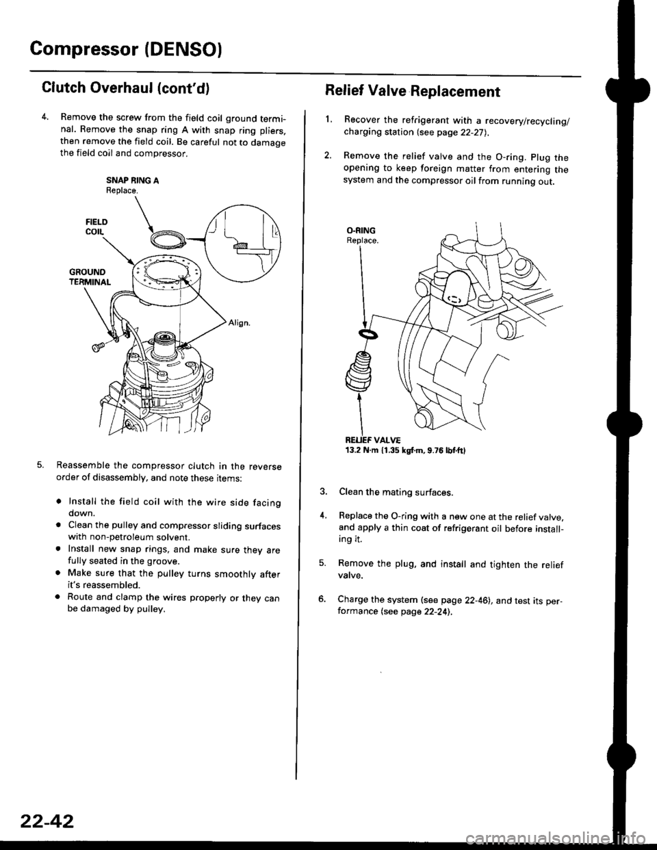
Remove the screw from the field coil ground termi-nal. Remove the snap ring A with snap ring pliers.
then remove the field coil. Be careful not to damaoethe field coil and compressor.
SNAP NING AReplace.
Reassemble the compressor clutch in the reverseorder of disassembly, and note these rrems:
o Install the field coil with the wire side facingdown.
a Clean the pulley and compressor sliding surfaceswith non-petroleum solvent.. Install new snap rings, and make sure thev arefully seated in the groove.
. Make sure that the pulley turns smoothly afterit's reassembled.
. Route and clamp the wires p.operly or they canbe damaged by pulley.
FIELOcorL
22-42
13.2 N.m 11.35 kgt m,9.76lbtttl
Relief Valve Replacement
L
4.
Recover the refrigerant with a recovery/recycling/charging station {see page 22-27),
Remove the relief valve and the O-ring. plug theopening to keep foreign matter from entering thesystem and the compressor oilfrom running out.
Clean the mating surfaces.
Replace the O-ring with a new one at the relief valve.and apply a thin coat of refrigerant oil before install-ing it.
Remove the plug, and install and tighten the reliefvatve.
Charge the system (see page 22-46), and test its per-formance (see page 22-24),
Page 1474 of 2189
Troubleshooting
Tips and Precautions (cont'dl
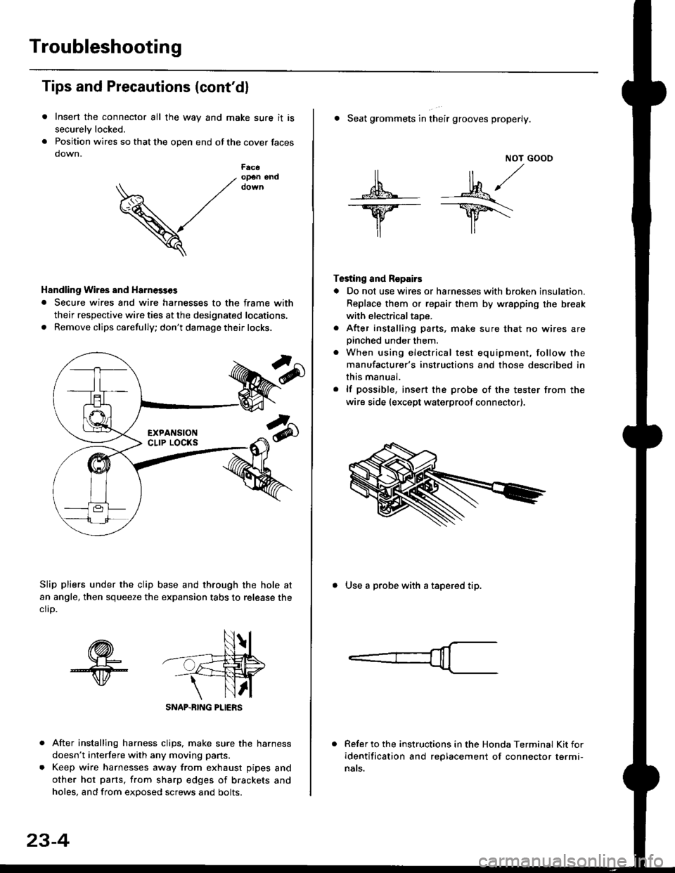
Insert the connector all the way and make sure it is
securelv locked.
Position wires so that the open end of the cover faces
down.
After installing harness clips, make sure the harness
doesn't interfere with any moving pans.
Keep wire harnesses away from exhaust pipes and
other hot parts. from sharp edges of brackets and
holes, and from exDosed screws and bolts.
V
F6c6op€n end
Handling Wires and Harnosscs
. Secure wires and wire harnesses to the frame with
their respective wire ties at the designated locations,
. Remove clips carefully; don't damage their locks.
Slip pliers under the clip base and through the hole at
an angle, then squeeze the expansion tabs to release the
clrp.
SNAP-BING PLIERS
23-4
NOT GOOO
ll il,/
s*' -.1}8."/_Y--_Y5\
il ,,
Testing and Repairs
o Do not use wires or harnesses with broken insulation.
Replace them or repair them by wrspping the break
with electricaltaoe.
. After installing parts, make sure that no wires arepinched under them.. When using electrical test equipment, follow the
manufacturer's instructions and those described in
this manual.
. lf possible, insert the probe of the tester from the
wire side (except waterproof connector).
. Seat grommets in their grooves properly.
. Use a probe with a tapered tip.
Refer to the instructions in the Honda Terminal Kit for
identification and replacement of connector termi-
nats.
Page 1561 of 2189
Battery
Test
@l. Battery lluid lelectrolytel contalns sulfuric acid. lt may cause severe burns it it gets on your skin ol in your eyes Wear
protective clothing and a face shield.
- It eleqtlolyte gets on your skin or clothes, rinse it off with watel immediately
- lf electrolyte gets in your eyes, flush it out by splashing water in your eyes for at least 15 minutes; call a physician
immediately.
. A battery gives off hydrogen gas. lf ignited, the hydrogen will explode and could crack the battery case and splatter
acid on you. Keep sparks, flames, and Gigarettes away from the battery'
o Overchaiging will raise the temperature oI the electrolyte. This may force electrolyte to spray out ot ths battery vents'
Follow the charger manufacturel's instrustions, and chalge the battery at a propcr rate.
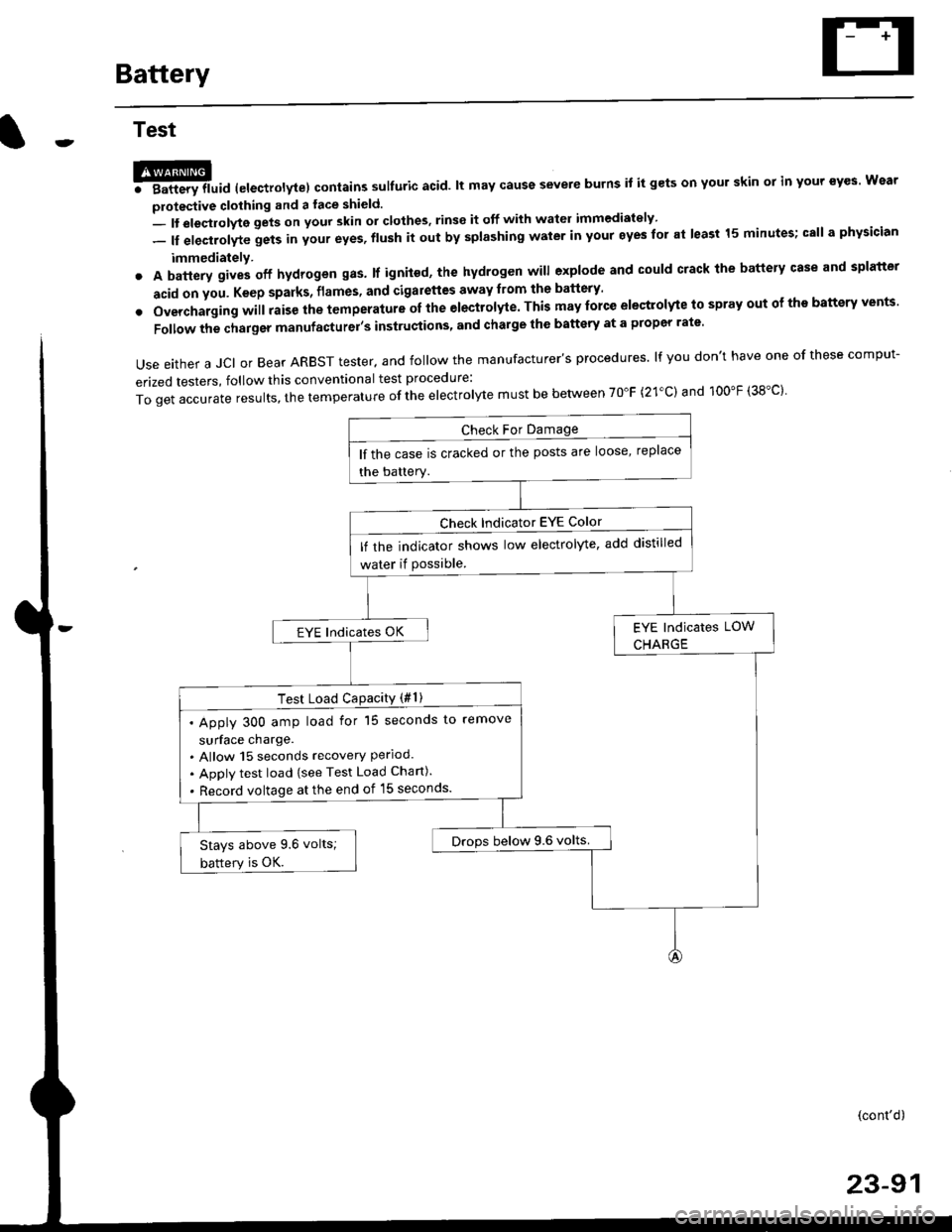
Use either a JCI or Bear ARBST tester. and follow the manufacturer's procedures. lf you don't have one of these comput-
erized testers, follow this conventional test procedure:
ToqetaccurateresuIts,thetemperatureoftheeIectro|ytemustbebetweenT0"F(21.c)and100"F(38.c}'
lf the case is cracked or the posts are loose, replace
the battery.
lf rhe indicator shows low electrolyte, add distilled
water if Possible.
EYE lndicates OK
Test Load CaPacitY (#l )
. Apply 300 amp load for 15 seconds to remove
surface charge.. Allow 15 seconds recovery Perloo.. Apply test load {see Test Load Chan).
. Record voltage at the end of l5 seconds.
Drops below 9.6 volts.Stays above 9.6 volts;
battery is OK.
(cont'd)
23-91