1997 HONDA CIVIC Face
[x] Cancel search: FacePage 1562 of 2189
Battery
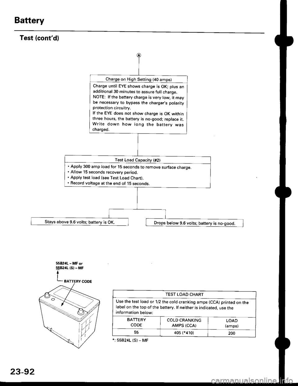
Test (cont'd)
Charge on High Sefting (40 amps)
Charge until EYE shows charge is OK; plus anadditional 30 minutes to assure full charge.NOTE: lf the battery charge is very tow, it maybe necessary to bypass the charger,s polarityprotection circuitry.
lf the EYE does not show charge is OK withinthree hours, the battery is no-good; replace it.Write down how long the battery wascharged.
Test Load Capacity (#2)
Apply 300 amp load for 15 seconds to remove surface charoe.Allow 15 seconds recovery period.
Apply test load {see Test Load Chan).
Record voltage at the end of 15 seconos.
Stays above 9.6 volts; battery is OK. ,] Drops below 9.6 volts; baftery is no-good.
tu,
TEST LOAD CHART
Use the test load or 1/2 the cold cranking amps {CCA) printed on thelabel on the top of the banery. lf neither is indicated. use theinformation below:
BArrERy coLb@
coDE I AMps (ccAl | {amps)
405 (*410)200
*:558241 (S) - MF
23-92
Page 1567 of 2189
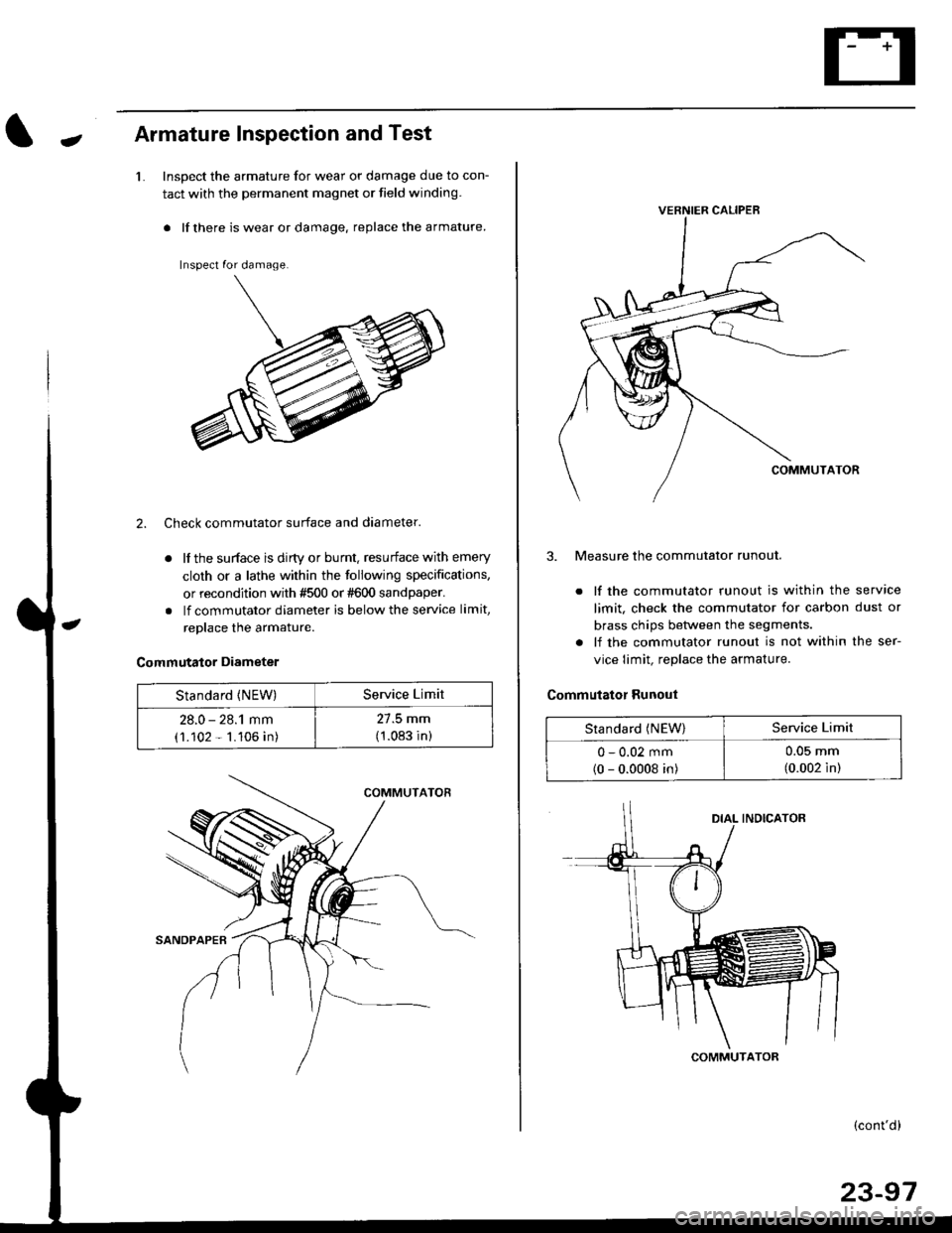
JArmature Inspection and Test
1.Inspect the armature for wear or damage due to con-
tact with the permanent magnet or field winding.
. lf there is wear or damage. replace the armature.
Inspect for damage.
2. Check commutator surface and diameter.
. lf the surface is dirty or burnt. resurface with emery
cloth or a lathe within the following specifications,
or recondition with #500 or #600 sandpaper.
. lf commutator diameter is below the service limit,
replace the armature.
Commutator Diameter
Standard {NEW)Service Limit
28.0 - 28.1 mm
(1.102 - 1.106 in)
27.5 mm
(1.083 in)
VERNIER CALIPEB
3. Measure the commutator runout.
. lf the commutator runout is within the service
limit, check the commutator for carbon dust or
brass chips betlveen the segments.
. lf the commutator runout is not within the ser-
vice limit, replace the armature.
Commutator Runout
Standard (NEW)Service Limit
0 - 0.02 mm(0 - 0.0008 in)
u-u!r mm
(0.002 in)
COMMUTATOR
(cont'd)
23-97
Page 1569 of 2189
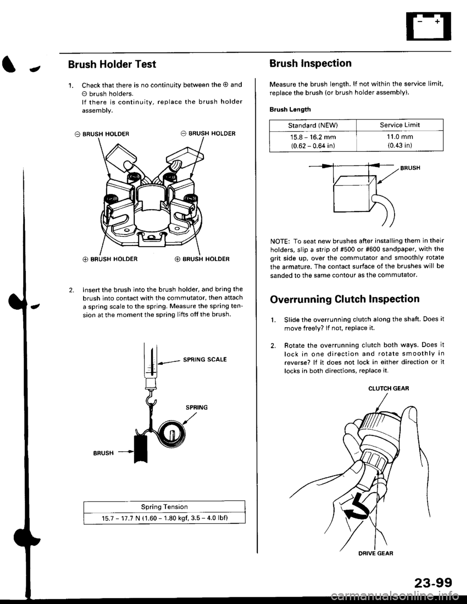
JBrush Holder Test
1. Check that there is no continuity between the O and
o brush holders.
lf there is continuity, replace the brush holder
assemoly.
O BRUSH HOLDER
@ BRUSH HOLDER€) BRUSH HOLDER
2. Insert the brush into the brush holder, and b.ing the
brush into contact with the commutator, then attach
a spring scale to the spring. Measure the spring ten-
sion at the moment the spring lifts off the brush.
SPRING SCALE
Spring Tension
15.7 - 17.7 N (1.60 - 1.80 kgf. 3.5 - 4.0 lbf)
ERUSH
Brush Inspection
Measure the brush length. lf not within the service limit,
replace the brush (or brush holder assembly).
Brush Length
NOTE: To seat new brushes after installing them in their
holders, slip a strip ot #500 or #600 sandpaper. with the
grit side up, over the commutator and smoothly rotate
the armature. The contact surface of the brushes will be
sanded to the same contour as the commutator.
Overrunning Clutch lnspection
Slide the overrunning clutch along the shaft. Does it
move freely? lf not, replace it.
Rotate the overrunning clutch both ways. Does it
lock in one direction and rotate smoothly in
reverse? lf it does not lock in either direction or it
locks in both directions, replace it.
2.
L
Standard (NEW)Service Limit
15.8 - 16.2 mm
(0.62 - 0.64 in)
1 1.0 mm
{0.43 in)
CLUTCH GEAR
DRIVE GEAR
Page 1638 of 2189
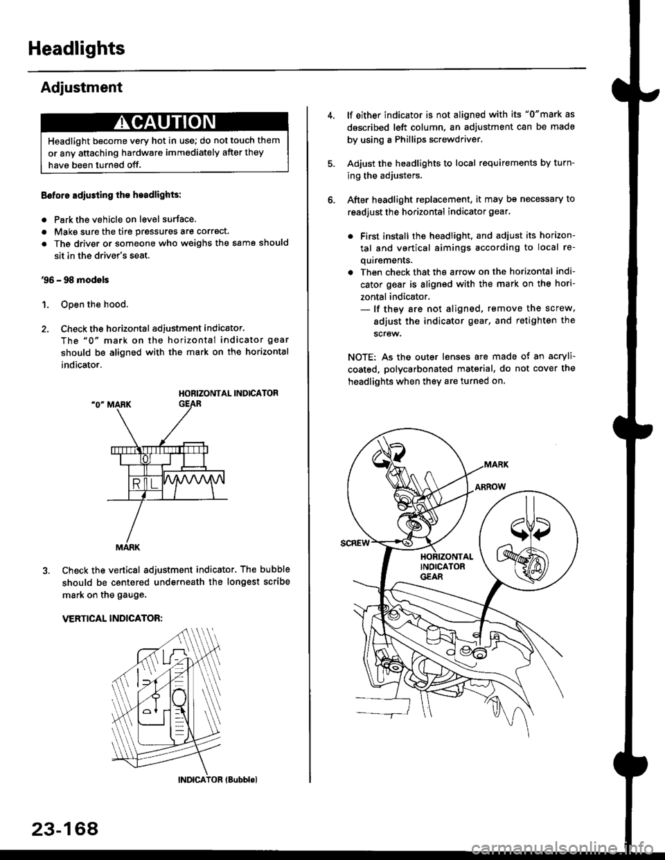
Headlights
Adjustment
Eoforo adiu3ting th€ h.adlights:
. Park the vehicle on level surface.
. Make sure the tire prgssures are correct.
a The driver or someone who weighs the same should
sit in the driver's seat.
96 - 98 modols
1. Open the hood.
2. Check the horizontal adjustment indicator.
The "0" mark on the horizontal indicator gear
should be aligned with the mark on the horizontal
indicator.
HORIZONTAL INDICATOR
Check the vertical adjustment indicator. The bubble
should be centered underneath the longest scribe
mark on the gauge.
VERTICAL INDICATOR:
Headlight become very hot in use; do not touch them
or any attaching hardware immediately after they
have been turnsd off.
MARK
23-164
(Bubblol
lf either indicator is not aligned with its "0"mark as
described left column, an adjustment can be made
by using a Phillips screwdriver.
Adjust the headlights to local requirements by turn-
ing the adjusters.
After headlight replacement, it may bs necessary to
readjust the horizontal indicator gear.
. First install the headlioht, and adjust its horizon-
tal and vertical aimings according to local re-
quirements.
. Then check that the arrow on the horizontal indi-
cator gear is aligned with the mark on the hori-
zontal indicator.- lf they are not aligned, remove the screw,
adiust the indicator gear, and retighten the
screw.
NOTE: As the outer lenses are made ot an acryli-
coated, polycarbonated material, do not cover the
headlights when they are turned on.
Page 1739 of 2189
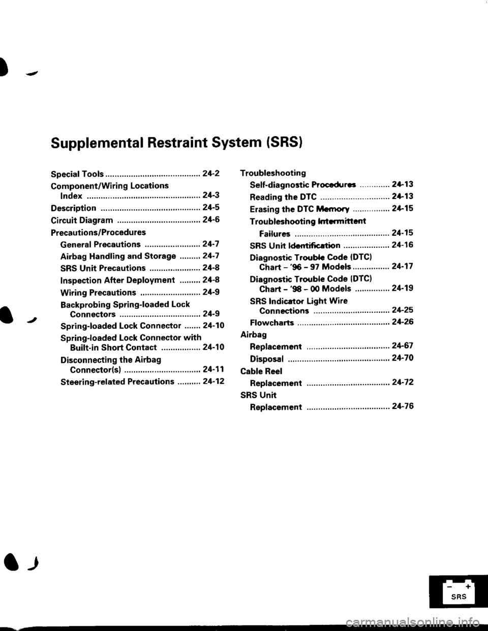
)
Troubleshooting
Sef f -dia gnostic Proctdurcs ............. 2+13
Reading the DTC .............................. 2+13
Erasing the DTC Mcnrory ................ 24-15
Troubleshooting h.ttnitt.nt
Failures ..............24-15
SRS U n it ldcntificrtion .................... 24- 1 6
Diagnostic Troublc Code (DTC)
Chart - '96 - 97 Models..."'."....... 24-17
Diagnostic Trouble Code (DTCI
Chart - '$ - 00 Models '.........""' 24'19
SRS lndicaror Light Wire
connections ...'.,24-25
Ff owcharts ........,,,,.24-26
Airbag
Repfacemant ...'.'...24-67
Disposaf .................24'70
Cable Reel
Repfacement .........24'72
SRS Unh
Repfacement ..'......24'76
l-l
-+
sRs
Supplemental Restraint System (SRSI
Speciaf Tools ... ...........24'2
Component/Wirin g Locations
fndex ................ ......24-3
Description ................ 24-5
Circuit Diagram ......." 24'6
Precautions/Procedures
Generaf Precautions ...............,,,,,,,.. 24-7
Airbag Handling and Storage .........24-7
SRS Unit Precautions ...................... 24-8
Inspection After Deployment ........' 24-8
Wiring Precautions ................... ....... 24'9
Backprobing Spring-loaded Lock
Connectors .......,24-9
Spring-loaded Lock Connectol ....,,. 24-10
Spring-loaded Lock Connector with
Built-in Short Contact ................. 24-10
Disconnecting the Airbag
Connector(sl .....' 24'11
Steering-related Precautions ...,.,.,,. 24'12
Page 1745 of 2189
Precautions/ Procedures
)General Precautions
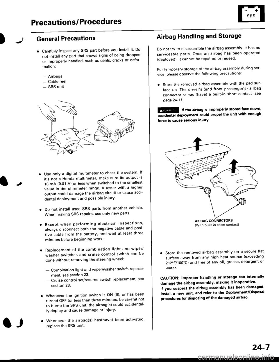
r Carefully inspect any SRS part before you install it Do
not install any part that shows signs of being dropped
or improperly handled' such as dents, cracks or defor-
mation:
- Airbags- Cable reel
- SRS unit
-
Use only a digital multimeter to check the system lf
it's not a Honda multimeter, make sure its output ls
1O mA (0.01 A) or less when switched to the smallest
value in the ohmmeter range. A tester with a higher
output could damage the airbag circuit or cause acci-
dental deployment and possible injury'
I Do not install used SRS parts from another vehicle
When making SRS repairs, use only new pans'
) Except when performing electrical inspections'
always disconnect both the negative cable and posl-
tive cable from the battery, and wait at least three
minutes before beginning work
r Replacement of the combination light and wiper/
washer switches and cruise control switch can be
done without removing the steering wheel:
- Combinalion light and wiper/washer switch replace
ment, see section 23
- Cruise control sevresume switch replacement' see
section 23.
. Whenever the ignition switch is ON {ll), or has been
turned OFF for less than three minutes' be careful not
to bump the SRS unit; the airbag(s) could accidental-
ly deploy and cause damage or injury'
. Whenever the airbag{s) has(have) been activated'
replace the SRS unit.l,
2+7
Airbag Handling and Storage
Do not try to disassemble the airbag assembly. lt has no
serviceable parts Once an airbag has been operated
(deployed). it cannot be repaired or reused'
For temporary storage of the airbag assembly during ser-
vice. olease observe the following precauttons:
. store the .emoved airbag assemblv with the pad sur-
face uo The driver's (and front passenger's) airbag
connecto''s'-as {have) a built.in short contact (see
page 2a-l 1
: | ..r r-+r-a k imninncrlv slorcd lace down,-""dd.r6t dtatltt-,tl could propel the unit whh enough
force lo c.usa 3a.ix! intury
AIRBAG CONNECTORS(With built in shon contact)
. Store the removed airbag assembly on a secure flat
surface away from any high heat source {exceeding
212"FI1OO"CJ and free of any oil' grease, detergent or
water.
CAUTION: lmproper handling or storage can intern'lJy
damage the airbag assembly, making it inoperativo
lf you suspect the airbag assembly has been dam€cd'
inslall a new unit. and relsr lo the Deployment/DisPG'l
olocedules for disposing ol the damaged airbag
Page 1805 of 2189
Airbag
)Replacement
After a collision in which the airbags were deployed' the
airbag assemblies and the SRS unit must be replaced'
!!!@ Store a removed airbag with the pad sur'
iFup. rr trt" airbag is improperly stored face down'
accidental deployment could propel the unit with
enough force to cause serious iniury'
CAUTION:
. Always disconnsct lhe airbag conn€ctor(s) when the
harness is disconnected.
. Do not disassemble or tamper with the ailbag'
NOTE:
. Do not install used SRS parts from another vehicle'
When repairing, use only new SRS parts'
o Carefully inspect the airbag before you install it Do
not insiall an airbag that shows signs oI being
dropped or improperly handled, such as dents' cracks
or deformation.
1. Disconnect the battery negative cable' then discon-
nect the positive cable from the battery' and wait at
least three minutes
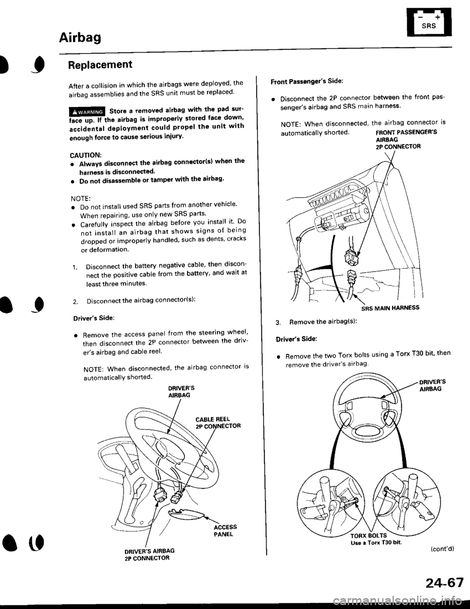
2. Disconnect the airbag connector(s):
Driver's Side:
. Remove the access panel from the steering wheel'
then disconnecl the 2P connector betlveen the driv-
er's airbag and cable reel
NOTE: When disconnected, the airbag connector ls
automaticallY shorted
ORIVER'SAIRBAG
DRIVEE'S AIRBAG2P CONNECTOR
oo
Front Passengel's Side:
. Disconnect the 2P connector between the front pas-
senger's airbag and SRS main harness'
NOTE: When disconnected, the airbag connector is
automaticallY shorted.FRONT PASSENGER'S
AIRBAG2P CONNECTOR
3. Bemove the airbag(s):
Driver's Side:
. Remove the two Torx bolts using a Torx T30 bit' then
remove the driver's airbag
(cont'd)
24-67
SRS MAIN HARNESS
Use a Torx T30 bitTORX BOLTS
Page 1810 of 2189
Gable Reel
Replacement
!@@ store a .emove airbag assambly with thepad surtace up. lf the airbag is improperly stored face
down, accidental deploymont could propel the unit withenough force to cause sorious iniury.
CAUTION:
. Alwsys disconnect the airbag connoctor(s) when ih€harness is disconngcted.
. Do not disassemble or tamper with the airbag.
NOTE: Carefully inspect the airbag assembly beforeinstalling it. Do not install an airbag that shows signs ofbeing dropped or improperly handled. such as dents,cracks or deformation.
l.Disconnect the battery negative cable. then discon-nect the positive cable from the battery, and wait atleast three minutes.
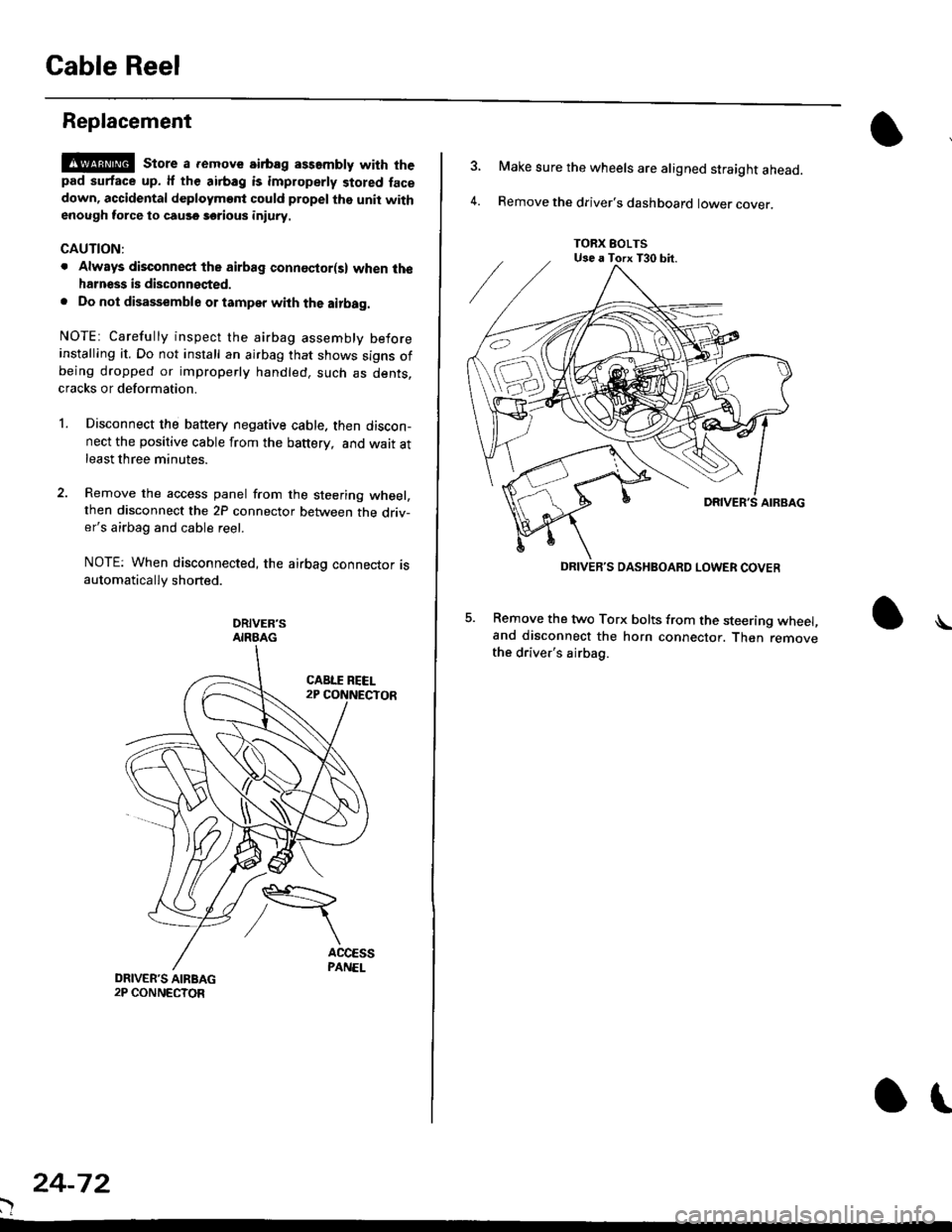
Remove the access panel from the steering wheel,then disconnect the 2P connector between the driv-er's airbag and cable reel.
NOTE: When disconnected, the airbag connector isautomatically shorted.
DRIVER'SAIRBAG
)
24-72
or
TORX EOLTSUse a Torx T30 bit.
DRIVEB'S DASHBOARD LOWER COVER
4.
Make sure the wheels are aligned straight ahead.
Remove the driver's dashboard lower cover.
5. Remove the two Torx bolts from the steering wheel,and disconnect the horn connector. Then removethe driver's airbag.
\