Page 1278 of 2189

Ouarter Glass
Installation (cont'dl
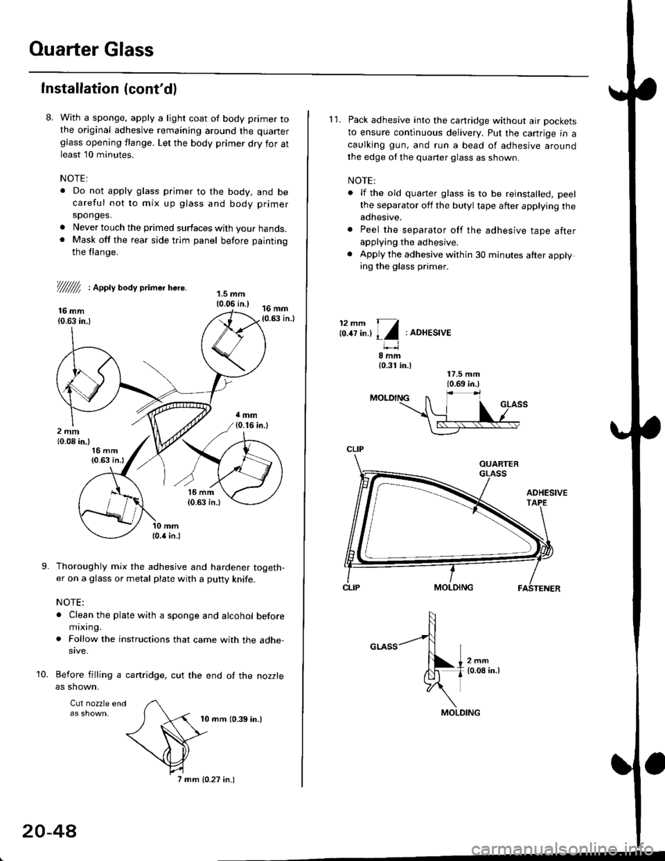
8. With a sponge, apply a light coat of body primer tothe original adhesive remaining around the quarter
glass opening flange. Let the body primer dry for atleast l0 minutes.
NOTE:
. Do not apply glass primer to the body, and becareful not to mix up glass and body primer
sponges.
. Never louch the primed surfaces with your hands.. Mask off the rear side trim panel before painting
the flange.
///ffi : Appty aoay primer here.
16 mm10.63 in.l
Thoroughly mix the adhesive and hardener togeth-er on a glass or metal plate with a putty knife.
NOTE:
. Clean the plate with a sponge and alcohol beforemixing.
. Follow the instructions that came with the adhe-sive.
Before filling a cartridge, cut the end of the nozzle
as shown.
Cul nozzle end
10 mrn (0.39 in.)
9.
10.
20-4A
7 mm 10.27 in.)
l'1. Pack adhesive into the canridge without air pockets
to ensure continuous delivery. Put the cartrige in a
caulking gun, and run a bead of adhesive around
the edge of the quarter glass as shown.
NOTE:
. lf the old quarter glass is to be reinstalled, peel
the separator off the butyl tape after applying theadhesive.
. Peel the separator off the adhesive tape afterapplying the adhesive.
. Apply the adhesive within 30 minutes after applying the glass primer.
12mm 11
lo.tt tn.l I l:ADHESIVE
8mm{0.31 in.)
CLIP
MOLDING
Page 1279 of 2189

}
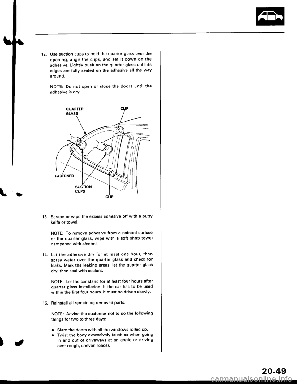
12. Use suction cups to hold the quarter glass over the
opening, align the clips, and set it down on the
adhesive. Lightly push on the quarter glass until its
edges are fully seated on the adhesive all the way
around.
NOTE: Do not open or close the doo.s until the
adhesive is dry.
Scrape or wipe the excess adhesive off with a putty
knife or towel,
NOTE: To remove adhesive from a painted surface
or the quaner glass, wipe with a soft shop towel
dampened with alcohol.
Let the adhesive dry for at least one hour, then
spray water over the quarter glass and check for
leaks. Mark the leaking areas, let the quarter glass
dry, then seal with sealant.
NOTE: Let the car stand for at least four hours after
quarter glass installation. lf the car has to be used
within the first four hours, it must be driven slowly
Reinstall all remaining removed parts-
NOTE: Advise the customer not to do the following
things for two to three days:
. Slam the doors with all the windows rolled up.
. Twist the body excessively (such as when going
in and out of driveways at an angle or driving
over rough, uneven roadsl.
13.
14.
)
CLIP
a
20-49
Page 1285 of 2189

L
L
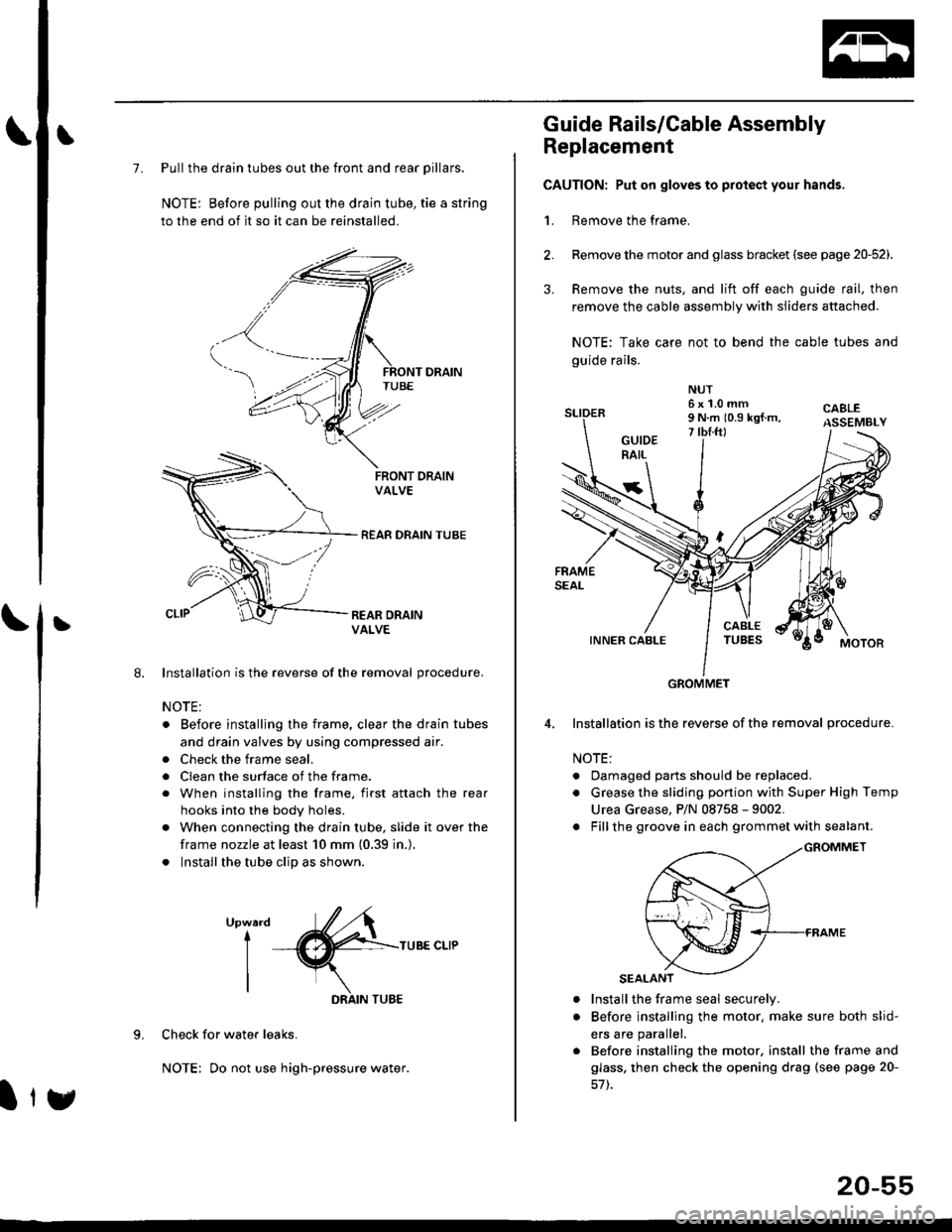
7. Pull the drain tubes out the front and rear pillars.
NOTE: Before pulling out the drain tube, tie a string
to the end of it so it can be reinstalled.
Installation is the reverse of the removal procedure.
NOTE:
. Before installjng the frame, clear the drain tubes
and drain valves by using compressed air.
. Check the frame seal.
. Clean the surface of the frame.
. When installing the frame, first attach the rear
hooks into the body holes.
. When connecting the drain tube, slide it over the
frame nozzle at least 10 mm (0.39 in.).
. Install the tube clip as shown.
UpwardI
I
I
TUBE CLIP
Check for water leaks.
NOTE: Do not use high-pressure water.
DRAIN TUBE
Ity
20-55
Guide Rails/Cable Assembly
Replacement
CAUTION: Put on gloves to protect your hands,
1. Remove the frame.
Remove the motor and glass bracket (see page 20-52).
Remove the nuts, and lift off each guide rail, then
remove the cable assembly with sliders attached.
NOTE: Take care not to bend the cable tubes and
guide rails.
Installation is the reverse of the removal procedure.
NOTE:
. Oamaged parts should be replaced.
. Grease the sliding portion with Super High Temp
Urea Grease, P/N 08758 - 9002.
. Fillthe groove in each grommet with sealant.
a
a
Install the frame seal securely.
Before installing the motor. make sure both slid-
ers are parallel.
Before installing the motor. install the frame and
glass, then check the opening drag (see page 20-
GROMMET
Page 1333 of 2189
Door and Side Moldings
Replacement
CAUTION: When prying with a flat-tip scr6wdrivgr, wrap it with protective tape to prevent damags'
NOTE;
. To remove the front side molding, remove the inner fender (see page 20-106)'
. To remove the door moiding, remove the door panel (see pages 20-4, 10, 16) and plastic cover.
. To removethe rearside molding, remove the side trim panel (see pages 20-60,611'
. Take care not to bend the door moldings.
. Before reassembling, clean the door bonding surface with a sponge dampened in alcohol'
. After cleaning, keep oil, grease and water from getting on the surface'
. lf necessary, replace any damaged clips.
4D:
FRONT DOORAdhesive areas.
2Dl3Dl
B>,3c>,2
REAR SIDEMOLOING
a: Plastic nut loc€tion. 1
@)
(cont'dl
20-103
MOLDING
>: Clip locations
A >: 4D, 112')13D,7
Page 1334 of 2189

Door and Side Moldings
Replacement (cont'dl
Door molding removal:
The following materials and tools are required to repairthe door moldings.
NOTE: Followthe manufacturer's instructions.
Materials: (Reference)
. Stripe remover
3M 08907
Stripe adhesive remover
3M 08908
Adhesive tape
3M Super Automotive Attachment Tape
Tools;
a Protective tape
. Knife or Cutter
. Sponge or Shop towel. Infrared dryer
. Film
. Putty knife
. Alcohol
CAUTION: Put on gloves to protect your hands,
Remove the door panel, and pull back the plastic
cover,
Apply protective tape on and around the molding.
3. Release the clips from inside of the door. Carefullvcut the adhesive tape with a knife or cutter whilepulling the edge of the molding away trom the dooras shown.
NOTE: Take care not to scratch or bend the mold-Ing.
1.
KNIFE
DOOR MOLDING
\
20-104
Door molding installation:
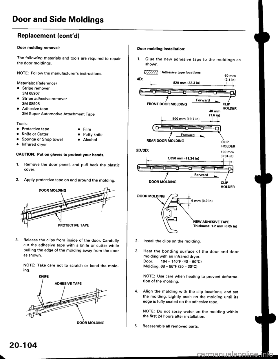
1. Glue the new adhesive tape to the moldings assnown.
[\\\l : Adhesive tape tocations60 mm4D: t2 t i^l
40 mm11.6 in)
Forward L
REAR DOOR
2Dl3Dl
CLIPHOLDER
100 mm(3.94 inl1,050 mm 141.34 inl
Forward !
DOOR MOLDING
DOOR MOLDING
5 mm {0.2 inl
ADHESIVE TAPEThickness: 1.2 mm 10.05 in)
Installthe clips on the molding.
Heat the bonding surface of the door and doormolding with an infrared dryer.
Door: 104 - 140"F (40 - 60.C)Molding: 68 - 86"F (20 - 30.C)
NOTE: Use care when heating to prevent deforma-tion of the molding.
Align the molding with the clip locations, and setthe molding. Lightly push on the molding until itsedge is fully seated on the adhesive tape.
NOTE: Do not spray water on the motding withinthe first 24 hours after installation.
Reassemble all removed pans.
Page 1336 of 2189
Inner Fender, Fenderwell rrim, Fuel Pipe protector and Rear
Air Outlet
Replacement
NOTE: lf necessary, replace any damaged clips.
Inner tender:
>: Screw locations,4
r\
tllpo" l:,/
>: Clip locations, 7
Fenderwell trim/Fuel pipe protector/Rea. air outlet:
NOTE:
. Take care not to bend the fenderwell trim.. Before lnstalling the fenderwell trim, clean the bodybonding surface with a sponge dampened in alcohol.. After cleaning, keep oil, grease or water from getting onthe surface.
. To remove the fuel pipe protector, first remove the rearwheel (see section 18).. To remove the rear air outlet, first remove the rearbumper (see page 20 95).
STEEL FENDERWELL
>: Clip locationsA>,4B>,4
l;1A
!--l1!
c >,2
I
tAh'frv
\:
+
\-
20-106
Page 1348 of 2189
Emblems
Installation
Apply the emblems where shown.
NOTE:
. Before applying, clean the body surface with a sponge dampened in alcohol.
. After cleaning, keep oil, grease and water from getting on the surface.
Aftachment Points (Reterence):
CIVIC EMBLEM
Unit: mm (in.)
CIVIC emblem
TFUNK LID
CIVIC emblem
TRUNK LID
Vorsion emblemVersion emblemVersion emblsm
20-114
Page 1369 of 2189
Emblems
Installation
Align the application tape with the taillight and body, as shown, then press the emblem into place. Remove the appticationtape.
NOTE:
o Before applying, clean the body surface with a sponge dampened in alcohol.. After cleaning, keep oil, grease and water from getting on the surface.. When applying, make sure there are no wrinkles in the emblem.
Attschment Point:
VERSION EMBLEM
20-140
DOHC VTEC aid€ omblom:Vsrsion emblem: