1997 HONDA CIVIC Face
[x] Cancel search: FacePage 1165 of 2189
)
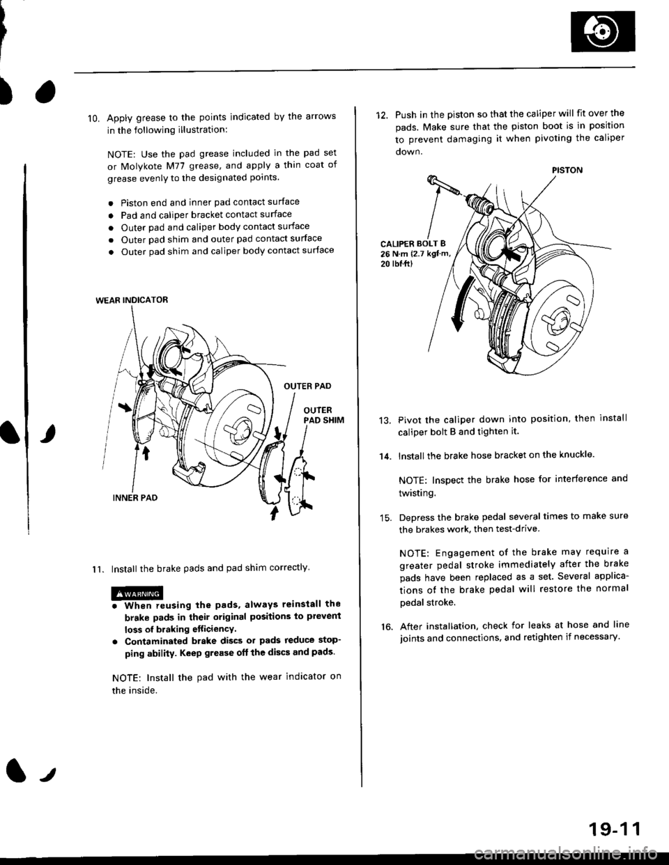
lO. Apply grease to the points indicated by the arrows
in the following illustration:
NOTE: Use the pad grease included in the pad set
or Molykote M77 grease, and apply a thin coat of
grease evenly to the designated points.
. Piston end and inner pad contact surface
o Pad and caliper bracket contact surface
. Outer pad and caliper body contact surface
. Outer pad shim and outer pad contact surface
. Outer pad shim and caliper body contact surface
OUTER PAD
OUIERPAD SHIM
I 1. Install the brake pads and pad shim correctly
@o When reusing the pads, always reinstall the
brake pads in their original positions to plevent
loss of braking etticiencY.
. Contaminated brake discs ol pads reduce stop-
ping ability. Keep grease oft the discs and pads.
NOTE: Install the pad with the wear indicator on
the inside.
WEAR INDICATOR
12. Push in the piston so that the caliper will fit over the
pads. Make sure that the piston boot is in position
to prevent damaging it when pivoting the caliper
CALIPER BOLT B26 N.m {2.7 kgt m,
20 rbl.ftl
14.
13.Pivot the caliper down into position, then install
caliper bolt B and tighten it.
lnstallthe brake hose bracket on the knuckle.
NOTE: Inspect the brake hose for interference and
twisting.
Depress the brake pedal several times to make sure
the brakes work, then test-drive
NOTE: Engagement of the brake may require a
greater pedal stroke immediately after the brake
pads have been replaced as a set. Several applica-
tions ot the brake pedal will restore the normal
pedal stroke.
After installation, check for leaks at hose and line
joints and connections, and retighten if necessary.16.
PISTON
19-1 1
Page 1166 of 2189
Front Brake Disc
Disc Runout Inspection
L
2.
Loosen the front wheel nuts slightly, then raise the
vehicle, and support it on safety stands. Remove
the front wheels.
Remove the brake pads (see page 19,8).
Inspect the disc surface for damage and cracks.
Clean the disc thoroughly and remove all rust.
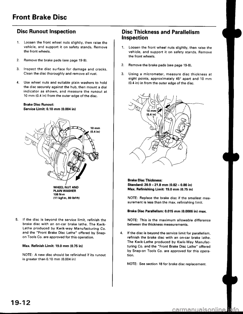
Use wheel nuts and suitable plain washers to hold
the disc securely against the hub, then mount a dial
indicator as shown, and measure the runout at
10 mm (0.4 in) from the outer edge of the disc.
Brake Disc Runout:
Service Limit: 0.10 mm (0.004 inl
WHEEL NUT ANOPLAIN WASHER'108 N.m(11 kg{.m, 80 lbf.ft)
lf the disc is beyond the service limit, refinish thebrake disc with an on-car brake lathe, The Kwik-Lathe produced by Kwik-way Manufacturing Co.and the "Front Brake Disc Lathe" offered by Snap-on Tools Co. are approved for this operation.
Max. Refinish Limit: 19.0 mm (0.75 in)
NOTE: A new disc should be refinished if its runout
is greater than 0.10 mm (0.004 in)
19-12
Disc Thickness and Parallelism
Inspection
1.Loosen the front wheel nuts slightly, then raise the
vehicle, and support it on safety stands. Remove
the front wheels.
Remove the brake pads (see page 19-8).
Using a micrometer, measure disc thickness at
eight points, approximately 45" apart and 10 mm(0.4 in) in from the outer edge of the disc.
Brake Dbc Thickn6s:
Standlrd: 20.9 - 21.8 mm (0.82 - 0.86 in)
Max. Refinishing Limit: 19.0 mm 10.75 inl
NOTE: Replace the brake disc if the smallest mea-
surement is less than the max. refinishinq limit.
Brake Disc Parallelism: 0.015 mm (0.fit06 in) max.
NOTE: This is the maximum allowable difference
between the thickness measurements.
lf the disc is beyond the service limit for parallelism,
refinish the brake disc with an on-car brake lathe.
The Kwik-Lathe produced by Kwik-Way Manufac-
turing Co. and the "Front Brake Disc Lathe" offered
by Snap-on Tools Co. are approved for this opera-
tion.
NOTE: See section 18 for brake disc reDlacement.
Page 1171 of 2189
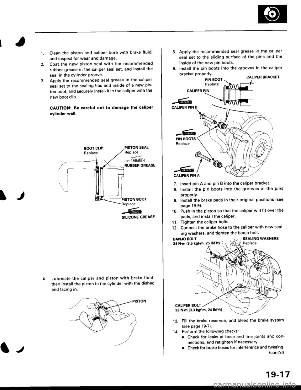
'1.Clean the piston and caliper bore with brake fluid,
and inspect for wear and damage.
Coat the new piston seal with the recommended
rubber grease in the caliper seal set. and install the
seal in the cylinder groove.
Apply the recommended seal grease in the caliper
seal set to the sealing lips and inside of a new pis-
ton boot, and securely install it in the caliper with the
new boot clip.
CAUTION: Be careful nol to damage the caliper
cylinder wall.
PISTON SEALReplace.
--^.,:=-qE!!!-HRUBBER GREASE
Lubricate the caliper and piston with brake fluid,
then install the piston in the cylinder with the dished
end facing in.
IJPISYON BOOTReplace.
j@i
SILICONE GREASE
CALIPER
-6lCALIPEB PIN B
Apply the recommended seal grease in the caliper
seal set to the sliding surface of the pins and the
lnside of the new pin boots.
lnstall the pin boots into the grooves in the caliper
bracket properly.CALIPER ERACKET
7. Insert pin A and pin B into the caliper bracket.
8. Install the pin boots into the grooves in the pans
propeny.
9. Install the brake pads in their original positions (see
page 19-9).
10. Push in the piston so that the caliper will fit over the
pads, and install the caliPer.
11. Tighten the caliper bolts.
12. Connect the brake hose to the caliper with new seal-
ing washers, and tighten the banjo bolt.
-6.lPIN BOOTSReplace.
-6lCALIPER PIN
BANJO EOLT34 N.m (3.5 kg{ m, 25 lbflt}SEALING WASHERSReplace.
'13.
CALIPER BOLT32 N.m 13.3 kgt.rn, 24lblft)
Fill the brake reservoit and bleed the brake system
{see page 19-7).
Perform the following checks:
. Check for leaks at hose and line joints and con-
nections. and retighten if necessary.
. Check for brake hoses for interference and twisting.(cont'd)
14.
19-17
Page 1173 of 2189
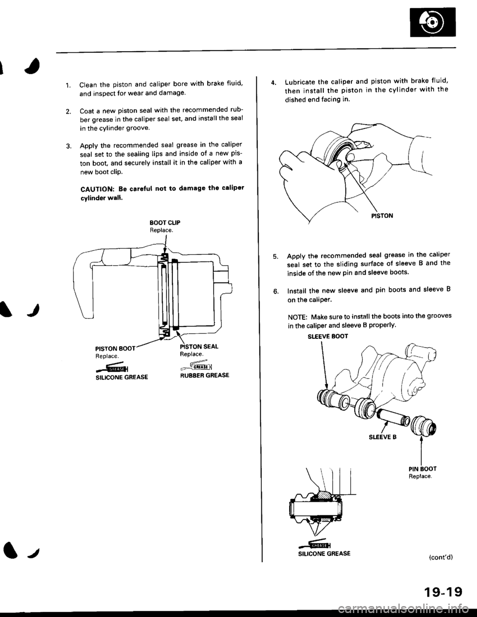
1.Clean the piston and caliper bore with brake fluid,
and inspect for wear and damage.
Coat a new Diston seal with the recommended rub-
ber grease in the caliper seal set, and installthe seal
in the cylinder groove.
Apply the recommended seal grease in the caliper
seal set to the sealing lips and inside ol a new pis-
ton boot, and securely install it in the caliper with a
new boot clip.
CAUTION: Be carelul not to damage ths calipor
cylinder wall.
Replace.
=_.-1!!4!!nRUBEER GREASE
IJ
Replace.
-6,SILICONE GREASE
t./
4. Lubricate the caliper and piston with brake fluid,
then install the piston in the cylinder with the
dished end facing in.
Apply the recommended seal grease in the caliper
seal set to the sliding surface oJ sleeve B and the
inside of the new pin and sleeve boots.
lnstall the new sleeve and pin boots 8nd sleeve B
on the caliDer.
NOTE: Make sure to install the boots into the grooves
in the caliper and sleeve B properly.
SI.EEVE BOOT
YPIN BOOTReplace.
(cont'd)
19-19
SLEEVE B
Page 1174 of 2189
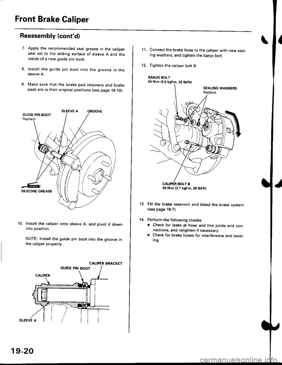
Front Brake Caliper
Reassembly (cont'dl
7.Apply the recommended seal grease in the caliperseal set to the sliding surface of sleeve A and theinside of a new guide pin boot.
Install the guide pin boot into the groove in thesleeve A.
Make sure that the brake pad retainers and brakepads are in their original positions (see page 19-10).
Install the caliper onto sleeve A, and pivot it downinto position.
NOTE: Install the guide pin boot into the groove inthe caliper properly.
BRACKET
SLEEVE A
19-20
11.Connect the brake hose to the caliper with new seal-ing washers, and tighten the banjo bolt.
Tighten the caliper bolt B.
Fill the brake reservoir and bleed the brake svstem(see page 19-7).
Perform the following checks.. Check for leaks at hose and line ioints and con-nectaons, and retighten if necessary.. Check for brake hoses for interference and twist-Ing.
13.
14.
BANJO BOLT
26 N.m (2.7 kgl.m, 20 lbtftl
Page 1179 of 2189
I
7.
11.
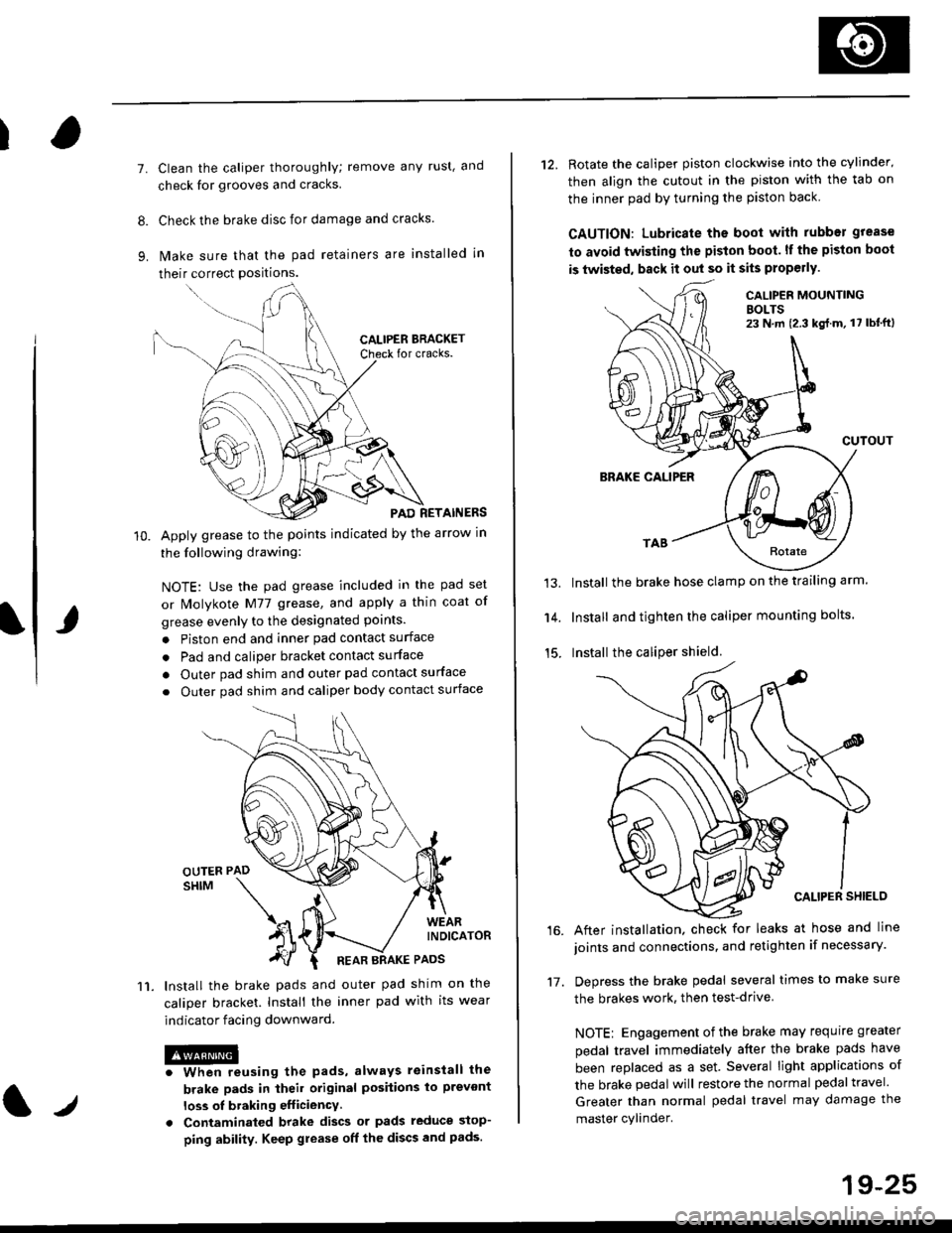
Clean the caliper thoroughly; remove any rust, and
check for grooves and cracks.
Check the brake disc for damage and cracks.
lvlake sure that the pad retainers are installed in
their correct positions.
PAD RETAINERS
Apply grease to the points indicated by the arrow in
the following drawing:
NOTE: Use the pad grease included in the pad set
or lMolykote M77 grease, and apply a thin coat of
grease evenly to the designated points.
. Piston end and inner pad contact surface
. Pad and caliper bracket contact surface
. Outer pad shim and outer pad contact surface
. Outer pad shim and caliper body contact surface
lnstall the brake pads and outer pad shim on the
caliper bracket. Install the inner pad with its wear
indicator facing downward.
@iwhen reusing the pads, always reinstall the
brake pads in iheil original posiiions lo prevont
loss ol braking efficiency
. Contaminaled brake discs or pads reduce stop-
ping ability. Keep grease off the discs and pads.
t./
19-25
12. Rotate the caliper piston clockwise into the cylinder'
then align the cutout in the piston with the tab on
the inner pad by turning the piston back
CAUTION: Lubricate ths boot with rubber grease
to avoid twisting the piston boot. lf the piston boot
is twisted, back it out so it sits properly.
CALIP€R MOUNTINGBOLTS23 N,m {2.3 kg{.m, 17 lbt'ft)
13.
14.
15.
CUTOUT
BRAKE CALIPER
Install the brake hose clamp on the trailing arm.
Install and tighten the caliper mounting bolts.
Install the caliper shield.
After installation. check for leaks at hose and line
joints and connections, and retighten if necessary.
Depress the brake pedal several times to make sure
the brakes work, then test-drive
NOTE: Engagement of the brake may requrre greater
pedal travel immediately after the brake pads have
been replaced as a set. Several light applications of
the brake pedal will restore the normal pedal travel.
Greater than normal pedal travel may damage the
master cylinder.
16.
17.
Page 1180 of 2189
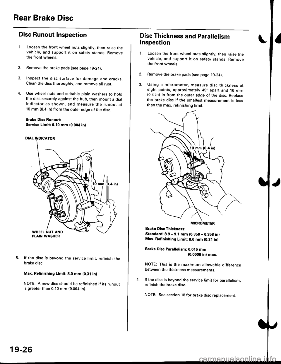
Rear Brake Disc
Disc Runout Inspection
1.Loosen the front wheel nuts slightly, then raise thevehicle, and suppon it on safety stands. Removethe front wheels.
Remove the brake pads (see page 19-24).
Inspect the disc surface for damage and cracks.Clean the disc thoaoughly, and remove a
rust.
Use wheel nuts and suitable plain washers to holdthe disc securely against the hub. then mount a dialindicator as shown. and measure the runout at10 mm (0.4 in) from the outer edge of the disc.
Brake Disc Runout:
Service Limit:0.10 mm {0.00,t in)
5. lf the disc is beyond the service limit, refinish thebrake disc,
Max. Retinishing Limit: 8.0 mm {0.31 in)
NOTE: A new disc should be refinished if its runoutis greater than 0.10 mm (0.004 in).
19-26
Disc Thickness and Parallelism
Inspection
1. Loosen the front wheel nuts slightly, then raise thevehicle, and support it on safety stands. Removethe front wh6els.
2. Remove the brake pads (see page j9-24).
3. Using a micrometer. measure disc thickness aterght points, approximately 45" apart and 1o mm{0.4 in) in from the outer edge of the disc. Replacethe brake disc if the smallest measurement is lessthan the max. refinishing limit.
Brake Disc Thickness:
Standard: 8.9 - 9.1 mm (0.350 - 0.358 in)Max. Rsfinishing Limit: 8.0 mm {0.31 in}
Brake Disc Parallelirm: 0.015 mm(0.0006 inl msx.
NOTE; This is the maximum allowable differencebetween the thickness measurements.
4. lf the disc is beyond the service limit for Darallelism.refinish the brake disc.
NOTE; See section 18 for brake disc replacement.
Page 1188 of 2189
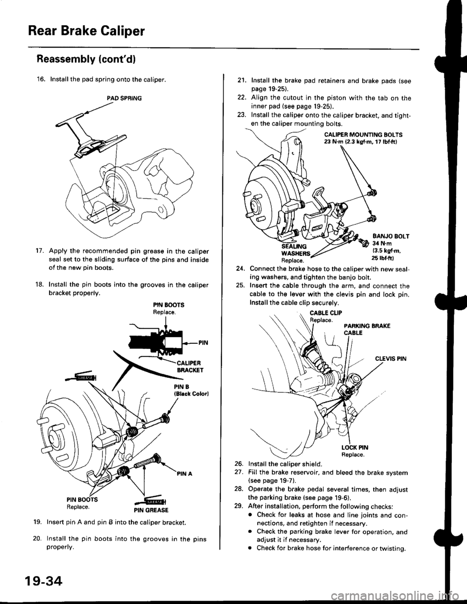
Rear Brake Caliper
Reassembly (cont'dl
'16. Installthe pad spring onto the caliper.
Apply the recommended pin groase in the caliper
seal set to the sliding surface of the pins and inside
of the new pin boots.
Install the pin boots into the grooves in the caliper
bracket properly.
PIN BOOTSReplsce.
(Bl.ck Colorl
PINRepl6ce.
19. Insert pin A and pin B into the caliper bracket.
20. Install the pin boots into the grooves in thepropefly.
PAD SPRING
11.
PIN GREASE
19-34
pr ns
22.
21. Install the brake pad retainers and brake pads (see
page 19-25).
Align the cutout in the piston with the tab on the
inner pad (see page 19-25).
Install the caliper onto the caliper bracket. and tight-
en the caliper mounting bolts.
CALIPER MOUNTING BOLTS23 N.m {2.3 kg{.m. 17 lbf.ft)
WASHERSReplace.
BANJO BOLT34 N.m13.5 kg{.m.25 rbtft)
24.Connect the brake hose to the caliper with new seal,
ing washers, and tighten the banjo bolt,
Insert ths cable through the arm, and connect the
cabls to the lever with the clevis pin and lock pin.
Install the cable clip securely.
CLEVIS PIN
-t
//t
LOCK PINRoplace.
26. Install the caliDer shield.
27. Fill the brake reservoir, and bleed the brake svstem(see page 19-71.
28. Operate the brake pedal several times, then adjust
the parking brake (see page 19-6).
29. After installation, perform the following checks:. Check for leaks at hose and line joints and con-nections, and retighten if necessary.. Check the parking brake lever for operation, and
adjust it if necessary.
. Check for brake hose for interference or twistinq.