Page 1052 of 2189
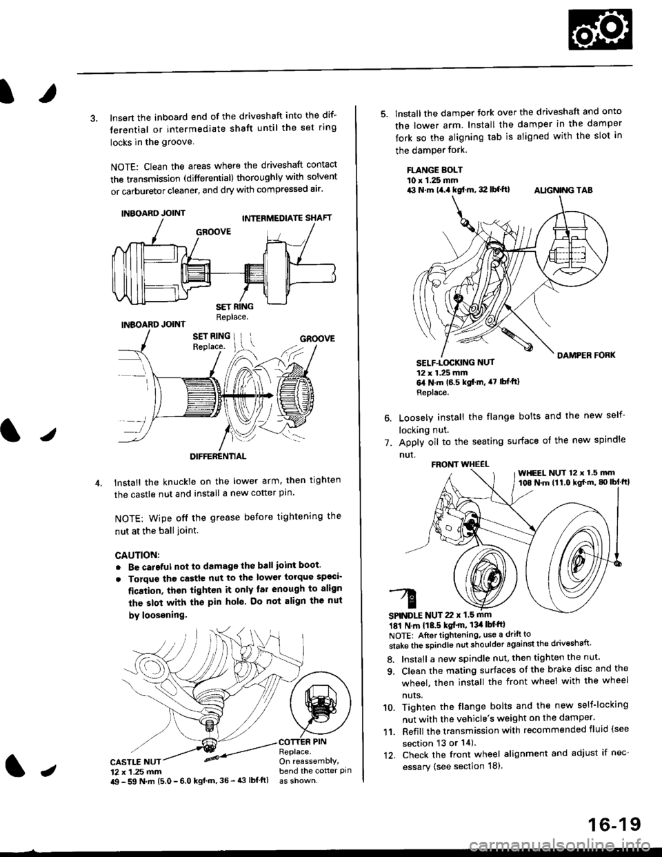
3. lnsert the inboard end of the driveshaft into the dif-
terential or intermediate shaft until the set ring
locks in the groove
NOTE: Clean the areas where the driveshaft contact
the transmission (differential) thoroughly with solvent
or carburetor cleaner, and dry with compressed air'
INBOARD JOINT
INBOARD JOINTReplace.
GROOVE
an
DIFFERENTIAL
lnstall the knuckie on the lower arm. then trghten
the castle nut and install a new cotter pin
NOTE: wipe off the grease before tightening the
nut at the ball ioint.
CAUTION:
. Be careful not to damago the ball ioint boot'
. Torque the castle nut to the lower torque sp€ci-
fication, thsn tighten it only far enough to align
the slot with th€ pin hol6. Do not align the nut
by loosening.
CASTLE NUT12 x 1 .25 mm
COTTER PINReplace.On reassemblY,bend the cotter pinJi$ - 59 N.m 15.0 - 6.0 kgl m,35 - 43 lbf ftl
16-19
5. lnstall the damper tork over the driveshaft and onto
the lower arm. Install the damper in the damper
fork so the aligning tab is aligned with the slot in
the damPer fork.
FLANGE BOLTl0 r 1.25 mmrit N.m t4.a kgf.m, 32 lbf.ft) AIIGN|NG TAB
1.
SELF-LOGKING NUT12 x 1.25 mm6,1N.m 16.5 kgi.m, a7 lbfftl
Replace.
Loosely install the flange bolts and the new self-
locking nut.
Apply oil to the seating surface of the new spindle
nut.
181 N m 118.5 kgt'm, 13il lbt'ftl
NOTE: Aftortightening, use a drift to
stake the spindle nut shoulder against the drivoshaft'
8. Install a new spindle nut, then tighten the nut'
9. Clean the mating surfaces ot the brake disc and the
wheel. then install the front wheel with the wheel
nuts.
10. Tighten the flange bolts and the new self-locking
nut with the vehicle's weight on the damper.
11. Refill the transmission with recommended fluid (see
section 13 or 14).'t2. Check the front wheel alignment and adjust if nec-
essary (see section 18),
FRONT WHEEL
SPINDLE NUT 22 x 1.5 mm
WHEEL NUT 12 x 1.5 mm108 N.m (11.0 kgl'm, g) lbl ftl
Page 1063 of 2189
)
Disassembly
'1.
2.
Place the gearbox in a vise with a soft jaws, then
clamp the gearbox at the mount bracket or gear
housing.
CAUTION: Be carcful not to distort the gear hous-
in9 by clamping it too iight in the vise incorrectly.
Remove the tie-rod end and locknut.
Remove the boot bands and tie-rod clips. Pull the
bogts away from the ends of the gearbox.
/
TIE.ROD CLIP
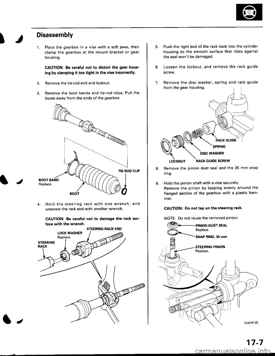
4. Hold the steering rack with one wrench, and
unscrew the rack end with another wrench.
CAUTION: Be caleful not to damagc the rack sur'
facs with the wrench.
STEERING RACK ENO
l,
17-7
7.
Push the right end of the rack back into the cylinder
housing so the smooth surface that rides against
the seal won't be damaged.
Loosen the locknut, and remove the rack guide
screw.
Remove the disc washer, spring and rack guide
from the gear housing.
RACK GUIOE
SPRING
8.
9.
LOCKNUT RACK GUIDE SCREW
Remove the pinion dust seal and the 35 mm snap
nng.
Hold the pinion shatt with a vise securely
Remove the pinion by tapping evenly around the
flanged section of the gearbox with a plastic ham-
met.
CAUTION: Do not tap on tho steering rack.
NOTE| Do not reuse the removed pinion.
9._
ViF=\_
PINION DUST SEALReplace.
SNAP RING,35 mm
STEERING PINIONFeplace.
DISC WASHER
Page 1066 of 2189
Steering Gearbox
Reassembly (cont'dl
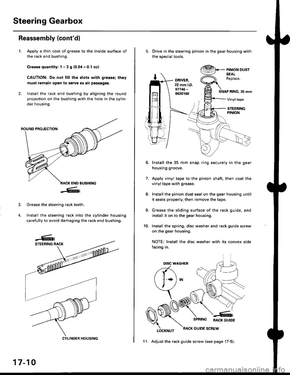
LApply a thin coat of grease to the inside surface of
the rack end bushing.
Grease quantity: 1 - 3 S 10.04-0.1 ozl
CAUTION: Do not till the slots with greas€; th€y
must remain open to serve as air passages,
Install the rack end bushing by aligning the round
projection on the bushing with the hole in the cylin-
der housing
4.
Grease the steering rack teeth.
Install the steering rack into the cylinder housing
carefully to avoid damaging the rack end bushing.
CYLINDER HOUSING
17-10
11. Adjust the rack guide screw (see page 17-5).
Drive in the steering pinion in the gear housing with
the soecial tools.
ORIVER.22 mm l.D.o7716-qr20100SNAP RING, 35 mm
PINION DUSTSEALReplace.
Vinyltape
STEERINGPINION
7.
Install the 35 mm snap ring securely in the gear
housing groove.
Apply vinyl tape to the pinion shaft, then coat the
vinyltape with grease.
Install the pinion dust seal on the gear housing until
it seats properly, then remove the tape.
Grease the sliding surface of the rack guide, and
install it on to the gear housing.
Install the spring, disc washer and rack guide screw
on the gear housing.
NOTE: Install the disc washer with its convex side
facing in.
LOCKNUT
SPRING RACK GUTDE
RACK GUIOE SCREW
10.
Dtsc w,
a(-\
l1 *l
\, ,/
\
Page 1068 of 2189
Steering Gearbox
Reassembly (cont'd)
21.
'19.
20.
Install the boot band so that the locking tabs of the
band (stake points) are in the range shown below.
{Tabs should face up and slightly forwaro.,
Bend both sets of locking tabs.
Lightly tap on the doubled-over portions to reduce
their height.
CAUTION: Stake the band locking tabs firmly.
22. Slide the rack right and left to be certain that the
boots are not detormed or twisted.
Stake points
+ Fronr
Lett Boot Band(Viewed from the left side)Right Boot Bend(Viewed from the right side)
17-12
Page 1081 of 2189
/
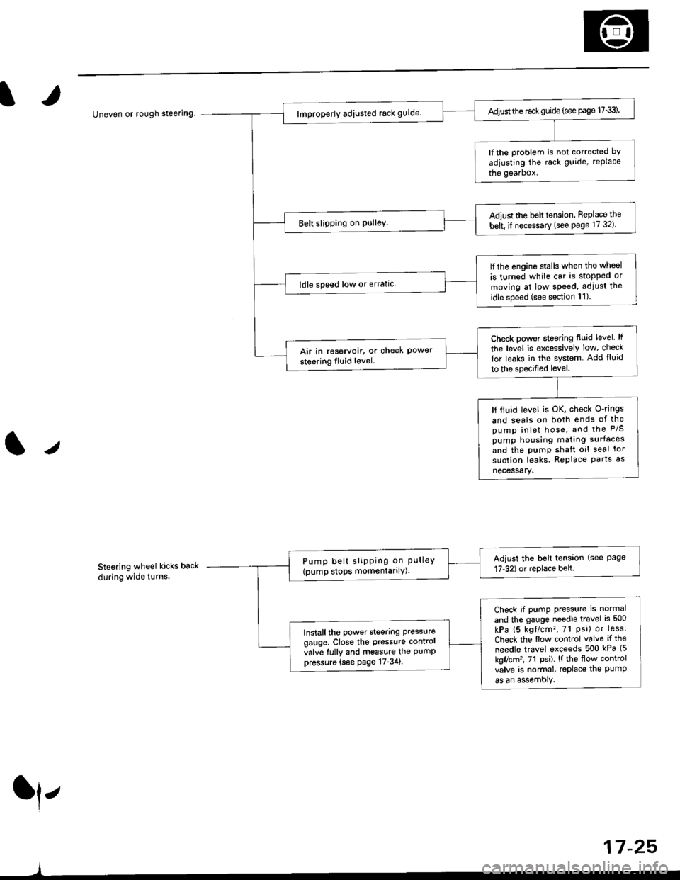
Uneven or rough steering
Steering wheel kicks back
during wide t!rns.
ll,
)
Adjust the rac* guide (see page 17-3).
lf the problem is not corrected bY
adjusting the rack guide, replace
the gearbox.
Adiust the belt tension. Feplace the
belt, il necessary (see Page 17 32).
lfthe engine stalls when the wheel
is turned while car is stopped or
moving at low speed, adjust the
idle spe€d (see section 11)
ldle speed low or erratic.
Check power sleering fluid level lf
the level is excessively low, check
lor leaks in the system. Add lluid
to the specified level.
Air in reservoir, or check Powersteering Iluid level.
lf ltuid level is OK, check O-rings
and seals on both ends of thepump inlet hose, and the P/Spump housing mating surfaces
and the pumP shaft oil seal for
suction leaks. RePlace Parts as
nocessary.
Adjust the belt tension (see Page17 32)or replace belt.Pump belt sliPPing on PLrlleY(pump stops momentarilY)
Check if pump press{rre is normal
and the gauge needle travel is 500
kPa (5 kgl/cm?, 7l Psi) or less.
Chock the flow control valve if the
needle travel exceeds 500 kPa (5
kgflcm'�, 71 Psi). l{ the flow control
valve is normal, replace the PumPas an assemoly.
Install the power steering pressure
gauge, Close the Pressure contrcl
valve fully and m6ssure the PumPpressure {s€e page 17-34}.
17 -25,
Page 1095 of 2189
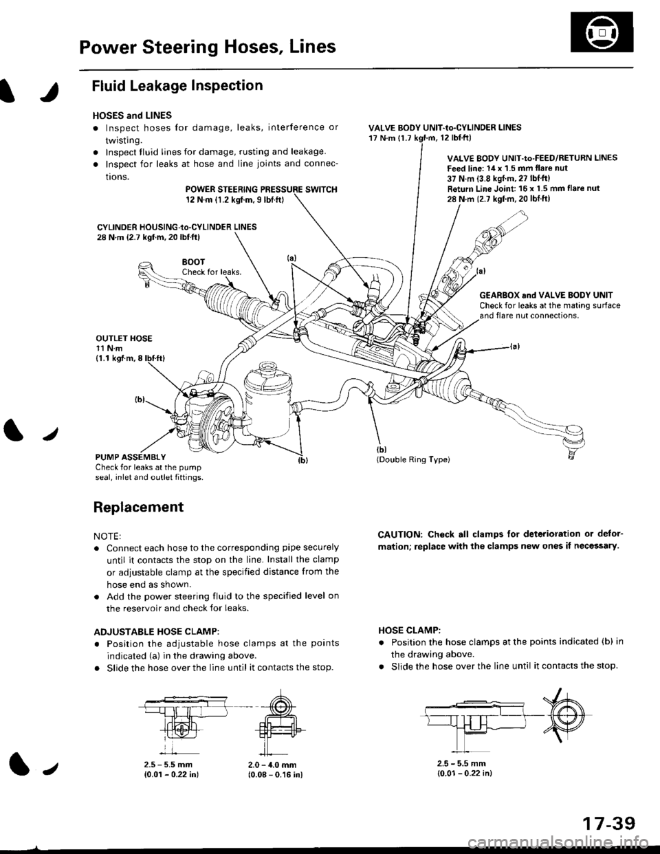
Power Steering Hoses, Lines
Fluid Leakage Inspection
HOSES and LINES
. Inspect hoses for damage, leaks, interference or
twisting.
. Inspect tluid lines for damage, rusting and leakage.
. Inspect for leaks at hose and line joints and connec-
tions.
POWER STEERINGswtTcH12 N.m {1.2 kgt.m,9lbt.ft}
CYLINDER HOUSING-to.CYLINDER LINES28 N.m (2.7 kgf.m, 20 lbf.ft)
VALVE BODY UNIT-to-CYLINDER LINES'17 N.m {1.712 tbl.ftl
VALVE BODY UNIT-Io-FEED/RETURN LINES
Feed line: 14 x '1.5 mm llare nut
37 N.m {3.8 kgJ.m, 27 lbf'tt)
Return Line Joint 16 x 1.5 mm flare nut
28 N m 12.7 kgf.m,20 lbtft)
HOSE CLAMP:
. Position the hose clamps at the points indicated (b) in
the drawing above.
. Slide the hose over the line until it contacts the stop.
8()07Check for leaks.
OUTLET HOSE11 N.m
G€AR8OX and VALVE BODY UNITCheck for leaks at the mating surfaceand flare nut connections,
tbt(Double Ring Typei
CAUTION: Check all clamps for deterioration or delor-
mation; replace with the clamps new ones il necessary.
(1.1 kgf.m,8
PUMP ASSEMBLYCheck for leaks at the pump
seal, inlet and outlet fiftings.
Replacement
NOTE:
. Connect each hose to the corresponding pipe securely
until it contacts the stop on the line. Install the clamp
or adiustable clamp at the specified distance from the
hose end as shown.
. Add the power steering fluid to the specified level on
the reservoir and check for leaks.
ADJUSTABLE HOSE CLAMP:
. Position the adiustable hose clamps at the points
indicated (a) in the drawing above.
. Slide the hose over the line until it contacts the stop.
2.5 - 5.5 mm{0.01 - 0.22 in)2.0 - 4.0 mm(0.08 - 0.16 in)
2.5 - 5.5 mm(0.01- 0.22 in)1.,
17-39
Page 1096 of 2189
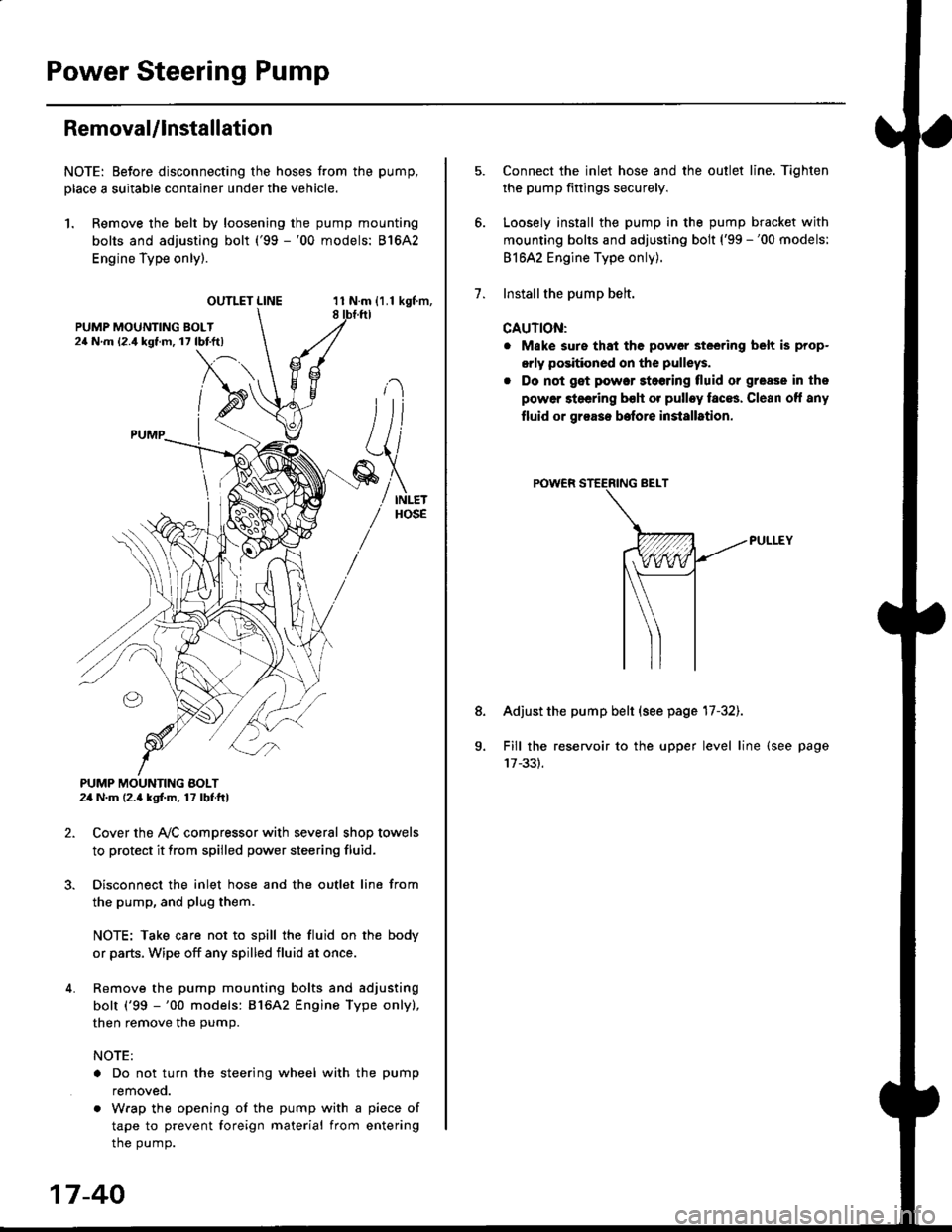
Power Steering Pump
RemovaUlnstallation
NOTE: Eefore disconnecting the hoses from the pump,
Dlace a suitable container under the vehicle.
1. Remove the belt by loosening the pump mounting
bolts and adjusting bolt ('99 -'00 models: 81642
Engine Type only).
OUTLET LINE11 N.m {1.1 kgf'm,8
L
PUMP MOUNTING BOLT24 N.m (2.4 kgl.m, 17 lbf ft)
2. Cover the Ay'C compressor with several shop towels
to protect it from spilled power steering fluid.
3. Disconnect the inlet hose and the outlet line from
the pump, and plug them.
NOTE: Take care not to spill the fluid on the body
or parts, Wipe off any spilled fluid at once.
4. Remove the pump mounting bolts and adjusting
bolt ('99 -'00 models: 816A2 Engine Type only),
then remove the pump.
NOTE:
. Do not turn the steering wheel with the pump
removeo.
. Wrap the opening of the pump with a piece of
tape to prevent foreign material from entering
the pump.
17-40
1.
8.
Connect the inlet hose and the outlet line. Tiqhten
the pump fittings securely.
Loosely install the pump in the pump bracket with
mounting bolts and adjusting bolt ('99 -'00 models:
81642 Engine Type only).
Installthe pump belt.
CAUTION:
. Make sure that the power steering belt is prop-
orly positioned on the pulleys.
. Do not get power stoering tluid or grease in the
power steering bsh or pulley faces. Clean off any
fluid or grease before installrtion.
Adjust the pump belt (see page 17-32).
Fill the reservoir to the upper level line (see page
Page 1101 of 2189
I
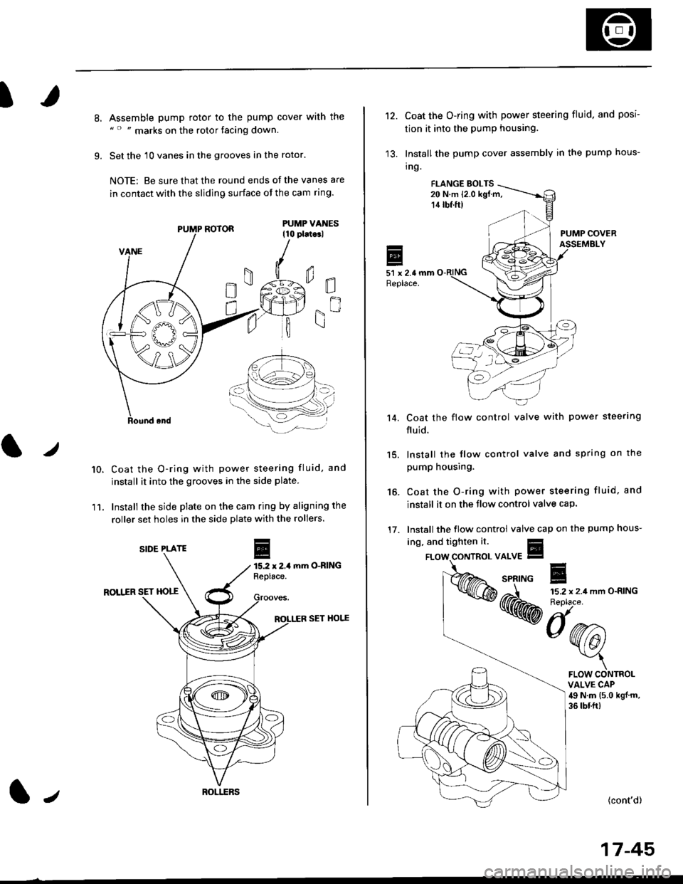
8.
9.
Assemble pump rotor to the pump cover with the" " " marks on the rotor facing down.
Set the 10 vanes in the grooves in the rotor.
NOTE: Be sure that the round ends ot the vanes are
in contact with the sliding surface of the cam ring.
Coat the O-ring with power steering fluid, and
install it into the grooves in the side plate.
Install the side plate on the cam ring by aligning the
roller set holes in the side plate with the rollers.
mm O-RING
ROLIIR SET HOTT
SET HOI.^E
0E
gn
10.
11.
r
E15.2 x 2,1Replace.
PUMP ROTOR
SIDE PLATE
ROI.I.ERSl,
't2.Coat the O-ring with power steering fluid. and posi
tion it into the pump housing.
Install the pump cover assembly in the pump hous-
tng.
FI.ANGE EOLTS20 N.m (2.0 kgf.m,14 tbf.ft)
PUMP COVERASSEMBLY
51 x 2.4 mmReplace.
Coat the flow control valve with power steerlng
fluid.
15. lnstall the flow control valve and spring on the
pump housing.
Coat the O-ring with power steering fluid, and
install it on the Jlow control valve cap.
Install the flow control valve cap on the pump hous-
't 4.
16.
17.
ing, and tighten it.
{cont'd)
17-45
FLOW CONTROLVALVE CAP49 N.m (5.0 kgj m,
36 tbf.ft)