1997 HONDA CIVIC air conditioning contro
[x] Cancel search: air conditioning controPage 66 of 2189
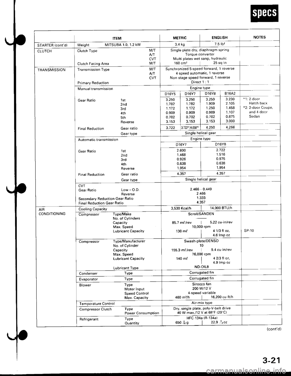
trEM I merntc ENGLISH NorEs
SfAnff n i*nt-i- W"'gf,t MllSUBA r.u, l.z kw r'4 rg
CLUTCHClutch Type
Clutch Facing Area
M/T
CVTM/T
Single plate dry, diaphragm springTorque converterMulti plates wet sanP, hYdraulic160 cm,25 sq in
Synchronized 5-speed forward, 1 reverse
4 speed automatic, 1 reverse
Non stage speed forward, 1 reverse
Direct 1 : 1
TRANSMISSIONTransmission Type
Primary Reduction
M/TArrCW
Manualtransmission
Gear Ratio 1st2nd3rd4th5thReverse
Final Reduction Gear ratio
Gear tYPe
Engine type
D16Y5 | D16Y7 D16Y8 I 81642
3.2501.1821.1120.9090.7023.153
3.2501.1821.1120.9090.7023.153
3.2501.9091.2500.9090.1023.153
3.2302.1051.4581.1070.8753.000
*1:2 doorHatch back+2r 2-door Coupe,and 4 doorSedan
3.122 13.122"11.053" 1 4.250 | 4.266
Single helicalgear
Engine type
D16Y7 | D16Y8Automatic transmission
Gear Ratio 'lst
2nd3rd4thReverse
Final Reduction Gear ratio
Gear tYPe
2.6001.4680.9260.6381.954
2.122
0.9750.6381.954
1.3514.357
cwGear Ratio Low - O.D.Reverse
Secondary Reduction Gear Ratio
Final Reduction Gear Ratio
2.466 0.4492.4661.3334.357
AIRCONDITIONING
Cooling Capacity3,530 Kcal/h14,000 BTU/h
Compressor Type/MakeNo. of CYlindersCaPacitYMax. SpeedLubricant CaPacitY
Scroll/SANDEN
85.7 m//rev 5.22 cu inkev10,000 rpm130 mf 41l3tl oz.
| 4.6 imp ozsP,10
Compressor Type/ManufacturerNo. of CylinderCapacityMax. SpeedLubricant CaPacitY
Lubricant TYPe
Swash-plate/DENso10155.3 mf /rev 9.4 cu_in/rev76,000 rpm140 mf | 4 2l3fl oz,I 4 9lmp ozND'OIL8
Condenser TypeCorrugated fin
Evaporator TyPeCorrugated fin
Elower TyPeMotor InputSPeed ControlMax. CaPacity
Sirocco fan200w112v4 speed variable460 m3/h 16,200 cu ft/h
Temperature Control
Compressor Clutch TyPePower ConsumPtionDry, single plate, PolY-V'belt drive40 W max./12 V at 68'F (20'C)
Refrigerant TyPeouantity
HFC 134a (R'134a)
650 gos | 22.9 isoz
(cont'd )
4 . J-Z I
Page 270 of 2189

!
Fuel and Emrsslons
SoecialToofs .....,...."..,. 11-2
Component Locations
lndex ....................., ......... 11-3
Svstem Description
Vacuum Connections ................,,..,.. ......... 11-12
Electrical Connections ...............,.,.,... ....... 11-29
System Connectors ........,.,.,.......................... 1 1-51
Troubleshooting
Troubleshooting Procedures ................. .. 11-81
Engine Control Module/PowertrainControl Module TerminalAfiangement ....,.,..... 11-88
Diagnostic Trouble Code Chart .................,., 11.97
How to Read Flowcharts .,.......................... . 11-103
PGM-Fl System
System Description ...... 11-10,1
Troubleshooting Flowcharts
Engine Control Module/PowertrainContlol Module ........ 11-107
Manitold Absolute Pressure Sensor .....'. . ... 11-115
fntake Air Temperatuie Sensor ..... . . ., . 11'121
Engine Coolant Temperatuae Sensol ........., 11-128
Throttle Position Sensor ...................,........... 11-132
Primary Heated Orygen Sensor (Sensor 1l ... 11-139
Secondary Heated Oxygen Sensor(Sensor 21.................................................... 1 1-153
Heated Oxygen Sensor Heater ...................,. 11-157
Fuel Supply System ...... 11-164
Random Mislire ......., ..11-166
Misfire Detected in One Cylindsr ................. 11-167
Knock Sensor .,.,............ 11-170
CKP/TDC/CYP Sensor ................................... 11'172
Vehicle Speed Sensor ...........,......,...,.,........... 1t-176
Barometric Pressure Sensor ...............,......... I 1-178
Electrical Load Detector,.,,............................ 1 1-179
CKF Sensor .................... 11-183
ECM/PCM Internal Circuit ............................. I 1-188
A/T Signal {TMA/TMBI .................................. I 1-189
ldle Control System
System Doscriplion ............ 11-190
Troubleshooting Flowcharts
ldle Control System ...... 11-192
ldle Air Control Va1ve .................................... I 1-19i1
Starter Switch Signal .................................... 1 1'202
Air Conditioning Signal ................................. 11'201
Ahernator FR Signal .................................... . 1 1-208
BrakeSwitch Signal ..................................... f 1"210
Power Sleering Prossure Switch Signal ......11-212
A/T Gear Position Signal ............................... 11-216
Clutch Swiich Signal ................................-.... 11-214
ldte Speed Setting . .............11-220
Fuel Supply System
Fuel Lines .,...................,.,.,.,11-221
Fuef Tube/Ouick-Connect Fittings ..........,.,........ 11 -227
System Description ....'.... 11-230
Fuel Pressure .......,.,,........... 11-230
Fuef fniectors ......................11-232
Fu€f Pressure Regulator .....,.......................'...,. 11-231
Fuef Fifter ............................11-235
Fuel Pump .............'.......'.... 11-236
PGM-FI Main Relay .............11'237
Fuel Tank ................ ....,...'.'.' 11'211
Intake Air System
System Description ....-.-.....11-243
Air Cfeaner ...........,......."". .11-211
Throttle Cable .....................11-211
Throttfe Body ........ ..'... . . .,.11-211
Fuel Iniestion Air Control System ,.,.,....-........... 11-250
Emission Control System
System Description .-..........11-252
Taifpip€ Emission ...............11-252
Three Way Catafytic Convert€r ............,.,,.,.,.,.... 11 -252
Exhaust Gas Racirculaiion System ...,.,,,,.,.,.,.,,. 11'254
Positive Crankcas€ Ventilation System .... . . .. 11-266
Evaoorative Emission Controls ..................,,..,.,. 11 -267
Page 373 of 2189

PGM-FI System
System Description
CKP/TDC/CYP Sensor
MAP Sensor
IAT SensorTP SensorEGR Valve Lift Sensor*'Primary H02SSecondary HO2SVSSBARO SensorELD*'KS€Starter SignalALT FR SignalAir Conditioning SignalA/T Gear Position SignalBattery Voltage {lGN.1}Erake Switch SignalPSP Switch SignalFuel Tank Pressure Sensor*iVTEC Pressure Switch*5Clutch Switch Signal*6Countershaft Speed SensornBMainshaft Speed Sensorrs
-\
----t /
F;ilrr j"-----fi-tri-'r.;l
Fb"t."'i" d" c;;il
F,h"'c;;tr*".io";-l
@."r.l"sc;;ll
EaM/PcM B""k-p F"""till
r\
-:/
Fuel IniectorsPGM-Fl Main Belay {Fuel Pump)MILIAC Valve!y'C Compressor Clutch RelayRadiator Fan Relay*,Condenser Fan RelayALT*'lcMEVAP Purge Control Solenoid
Primary HO2S HeaterSecondary H02S HeaterEGR Control Solenoid Valve*rEGR valve*6EVAP Bypass Solenoid Valve*'EVAP Control Canister Vent Shut
VTEC Solenoid Valve*5DLCLock-up Control Solenoid Valve*aShift Control Solenoid Valve*3Linear Solenoid Valve*3
*1: Dl6Y5 engine*2: USA model*3: CW (D16Y5 ensine), D16Y8 engine and 81642 ensine*4: '96 D16Y8 engine lcoupe),'97 Dl6Y7 engine (coupe: KL model, sedan: KL (LX) model),'97 D16Y8 engine {coupe: all models, sedan: KLmodel),'98-all models,'99'all models,'00-all models+5: D16Y5, D16Y8,816A2 engine*6: M/T (D16Y5 enginei*7: CVT 1D'l6Y5 engine)+8: A/T (D16Y7, D16Y8 engine)*9: '96 D16Y5 engine,'96 D16Y7 engine,'96 Dl6Y8 engine (sedan),'97 D16Y5 engine,'97 Dl6Y7 engine (coupe: KA, KC models, sedan:KA, KC, KL (LX) models, hatchback: all models),'97 D16Y8 engine (sedan: KA, KC modelsi
PGM-FI Sy3lem
The PGM-Fl system on this model is a sequential multipon fuel injection system.
Fuel iniector Timing and Duration
The ECM/PCM contains memories for the basic discharge durations at various engine speeds and manifold air flow rates.
The basic discharge duration, after being read out from the memory. is further modified by signals sent from various sen-
sors to obtain the final discharge duration.
ldle Air Control
ldle Air Control Valve llAC Valve)
When the engine is cold. the A,/C compressor is on, the transmission is in gear, the brake pedal is depressed, the P/S load
is high, or the alternator is charging, the ECM/PCM controls current to the IAC Valve to maintain the correct idle speed.
lgnition Timing Control
. The ECM/PCM contains memories for basic ignition timing at various engine speeds and manifold air flow rates.
lgnition timing is also adjusted for engine coolant temperature.
. Aknockcontrol system was adopted which sets the ideal ignition timing for the octane rating ofthegasoline used.*3
Othgr Control Funqtions
1. Starting Control
When the engine is started, the ECM/PCM provides a rich mixture by increasing fuel injector duration.
2. Fuel Pump Control
. When the ignition switch is initially turned on, the ECM/PCM supplies ground to the PGM-Fl main relay that sup-plies current to the fuel pump for two seconds to pressurize the fuel system.. When the engine is running, the ECI\4PCM supplies ground to the PGM-FI majn relay that supplies current to the fuel
oumo.
. When the engine is not running and the ignition is on, the ECM/PCM cuts ground to the PGM-FI main relay which
cuts current to the fuel pump.
11-104
INPUTS
ENGINE CONTROL MODULE (ECMY
POWERTRAIN CONTROL MODULE (PCM) OUTPUTS
Page 374 of 2189

3.
5.
6.
1.
Fuel Cut-off Control
. During deceleration with the throttle valve closed, current to the fuel injectors is cut off to improve fuel economy at
speeds over the following rpm:. D16Y5 engine (M/T):850 rpm. D]6Y5 engine (CVT), D'16Y8 engine (USA M/T): 920 rpm
. Dl6Y8 engine (USA A,/I), D16Y7 engine (USA A,/T);910 rpm
. D16Y8 engine (Canada M/T), D16Y7 engine (canada): 990 rpm
' D16Y8 engine (Canada M/T): 1,000 rpm
. 816A2 engine: 970 rpm
. Fuel cut-off action also takes place when engine speed exceeds 6,900 rpm (D16Y5, D16Y7 engine; D'16Y8 engine:
7,000 rpm. 816A2 engine: 8.100 rpm), regardless of the position of the throttle valve, to protect the engine from
over-rewing. With '99 Dl6Y7 engine (A,/T) and '99 D16Y8 engine (A./T), the PCM cuts the fuel at engine speeds over
5,000 rpm when the vehicle is not moving.
IVC Compressor Clutch Relay
When the ECM/PCM receives a demand for cooling from the air conditioning system, it delays the compressor from
being energized, and enriches the mixture to assure smooth transition to the A,/C mode
Evaporative Emission (EVAP) Purge Control Solenoid Valve*'
When the engine coolant temperature is above 154'F (68'C). the ECM/PCM controls the EVAP purge control solenoid
valve which controls vacuum to the EVAP purge control canister.
Evaporative Emission (EVAP) Purge Control Solenoid Valve*a
When the engine coolant temperature above 154"F (68"C), intake air temperature above 32"F (0'C) and vehicle speed
above 0 mile (0 km/h) or [Ay'C compressor clutch on and intake air temperature above 160"F (41'C)], the ECM/PCM
controls the EVAP purge control solenoid valve which controls vacuum to the EVAP purge control canister.
Exhaust Gas Recirculation (EGR) Control Solenoid Valve*?
When EGR is required for control of oxides of nitrogen (NOx) emissions. the ECM controls the EGR control solenoid
valve which supplies regulated vacuum to the EGR valve
Alternator Control
The system controls the voltage generated at the alternator in accordance with the electrical load and driving mode,
which reduces the engine load to improve the fuel economy.
ECM/PCM Fail-safe/Back-up Functions
1. Fail safe Function
When an abnormality occurs in a signal from a sensor, the ECM/PCM ignores that signal and assumes a pre-pro-
grammed value for that sensor that allows the engine to continue to run.
2. Back-uD Function
When an abnormality occurs in the ECM/PCM itself, the fuel injectors are controlled by a back-up circuit independent
of the system in order to permit minimal driving.
3. Self diagnosis Function lMalfunction Indicator Lamp (MlL)l
When an abnormality occurs in a signal from a sensor, the ECM/PCM supplies ground for the lvllL and stores the DTC
in erasable memory. When the ignition is initially turned on, the ECM/PCM supplies ground for the MIL for two sec-
onds to check the MIL bulb condition.
4. Two Trip Detection Method
To prevent false indications, the Two Trip Detection Method is used for the HO2S, fuel metering-related. idle control
system, ECT sensor, EGR system and EVAP control system self-diagnostic functions. When an abnormality occurs,
the ECM/PCM stores it in its memory. When the same abnormality recurs after the ignition switch is turned OFF and
ON 0l) again, the ECM/PCM informs the driver by lighting the MlL. However, to ease troubleshooting, this function is
cancelled when you jump the service check connector. The MIL will then blink immediately when an abnormality
occurs,
5. Two (or Three) Driving Cycle Detection Method
A "Driving Cycle" consists ot starting the engine. beginning closed loop operation, and stopping the engine. lf misfir-
ing that increases emissions is detected during two consecutive driving cycles, or TWC deterioration is detected dur-
ing three consecutive driving cycles, the ECM/PCM turns the MIL on. However, to ease troubleshooting, this function
is cancelled when you jump the service check connector. The MIL will then blink immediately when an abnormality
occurs.
(cont'd)
1 1-1 05
.1.
Page 460 of 2189
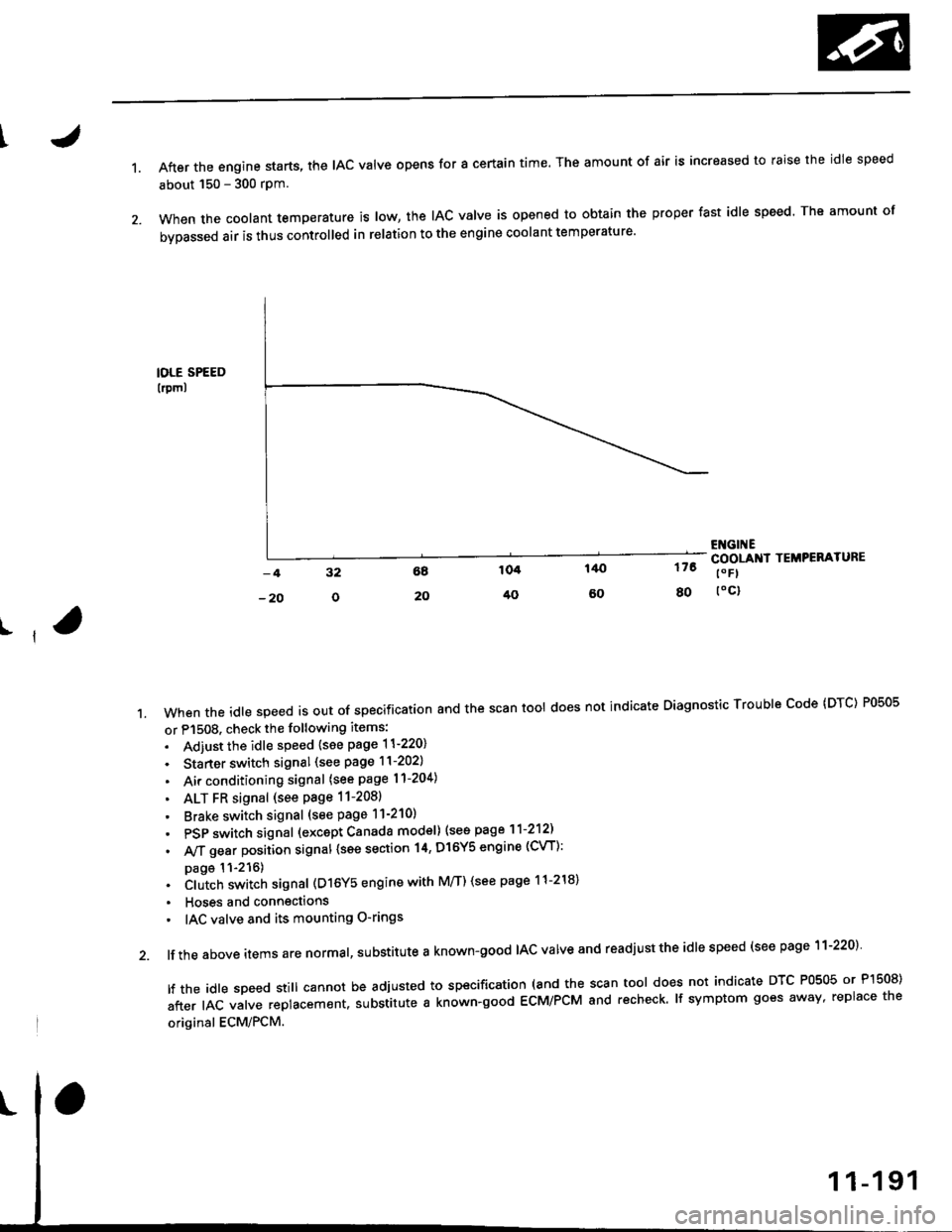
1.After the engine starts, the lAc valve opens for a certain time. The amount of air is increased to raise the idle speed
about 150 - 300 rpm.
When the coolant temperature is tow, the IAC valve is opened to obtain the proper fast idle speed. The amount of
bypassed air is thus controlled in relation to the engine coolant temperature'
IOLE SPEED
lrpml
176
80
ENGI ECOOLANI TEMPERATURE
t" Fl
toc)
ll
't.Whentheid|espeedisoutofspeciiicationandthescantoo|doesnotindicateDiagnosticTroub|ecode(DTc)P0505
or P1508. check the following items:
. Adiust the idle speed {see page 11-220}
. Starter switch signal (see page 11-202)
. Air conditioning signal (see page l1-204)
. ALT FR signal (see Page 11-2081
' Brake switch signal (see page 11-210)
. PSP switch signal (excapt Canada model) (see page 11-212)
. A,/T gear position signal {see section 14, Dl6Y5 engine (CVT):
page 11-216). Clutch switch signal (D16Y5 engine with M/T) (see page 11-218)
. Hoses and connections
' IAC valve and its mounting O-rings
lf the above items are normal, substitute a known-good IAC valve and readjust the idle speed (see page 11-220)
|ftheid|espeedsti||cannotbeadjustedtospecification(andthescantoo|doesnotindicateDTcP0505orP]50S)
after IAC valve replacement. substitute a known-good ECM/PCM and recheck. lf symptom goes away, replace the
original ECM/PCM.
Page 475 of 2189
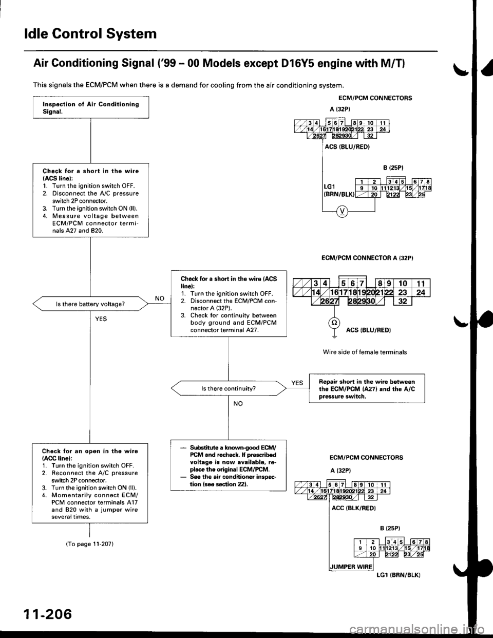
ldle Control System
Air Conditioning Signal ('99 - 00 Models except Dl6Y5 engine with M/Tl
This signals the ECM/PCM when there is a demand for cooling from the air conditioning system.
ECM/PCM CONNECTORS
a l32P)
ECM/PCM CONNECTOR A {32P)
Wire side of female terminals
ECM/PCM CONNECTORS
A (32P1
Chock tor a short in ihe wi.e(ACS lin6):1. Turn the ignition switch OFF.2. Disconnect the A/C pressure
switch 2P connector.3. Turn the ignition switch ON (ll).
4. Measure vo ltage betweenECM/PCM connector terminals A27 and 820.
Check for a short in the wire (ACS
linel:'1. Turn the ignition switch OFF.2. Disconnect the ECM/PCM connector A (32P).
3. Check lor continuity betweenbody ground and ECM/PCMconnector terminal A27.
Reoair short in lhe wi.e botweonthe ECM/PCM (A271 and rhe A/Cpressure swilch.
Srr66tituto a known{ood ECM/PCt4 tnd rechock. It prascrib€dvoltage is now available, re-plac€ the original ECM/rcM.Soo the air conditioner insoec-tion {see s€ction 22}.
Check to. an opon in tho wi.e(ACC linel:1. Turn the ignition switch OFF.2. Reconnect the A/C pressure
switch 2P conneclor.3. Turn the ignition switch ON (ll).
4. Momentarily connect ECN4/PCM connector terminals A17and 820 with a jumper wire
(To page '! 1-207)
11-206
LGl {BRN/BLK)
Page 1380 of 2189
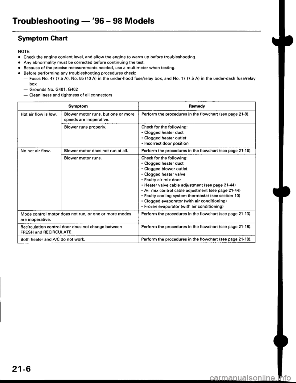
Troubleshooting -'96 - 98 Models
Symptom Chart
NOTE;
. Check the engine coolant level. and allow the engine to warm up before troubleshooting.
. Any abnormality must be corrected before continuing the test.
. Because of the precise measurements needed. use a multimeter when testing.
o Before performing any troubleshooting procedures check:- Fuses No. 41 11.5 Al, No. 55 (40 A) in the under-hood fuse/relay box. and No. 17 (7.5 A) in the under-dash fuse/relay
box- Grounds No. G401, G402- Cleanliness and tightness of all connectors
SymptomRomedy
Hot air flow is low.Blower motor runs. but one or more
speeds are inoperative.
Perform the procedures in the flowchart (see page 21-8).
Blower runs properly.Check for the following:. Clogged heater duct. Clogged heater outlet. Incorrect door position
No hot air flow.Blower motor does not run at all,Perform the procedures in the flowchart (see page 21-10).
Blower motor runs.Check for the following:. Clogged heater duct. Clogged blower outlet. Clogged heater valve. Faultv air mix door. Heater valve cable adjustment (see page 21-44). Air mix control cable adiustment (see page 2'l-441. Faulty cooling system thermostat (see section 10). Clogged evaporator (with air conditioning). Frozen evaporator {with air conditioning)
Mode control motor does not run, or one or more modes
are inooerative.
Perform the procedures in the flowchart (see page 21-13).
Recirculation control door does not chanqe between
FRESH and RECIRCULATE.
Perform the procedu.es in the flowchan (see page 21-16).
Both heater and A,/C do not work.Perform the procedures in the flowchart (see page 21-18),
21-6
Page 1411 of 2189
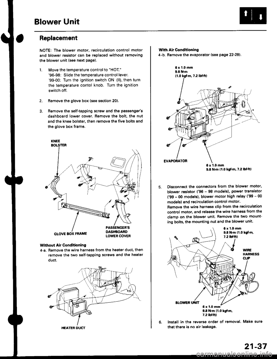
Blower Unit
Replacement
NOTE: The blower motor, recirculation control motor
and blower resistor can bs replacsd without rsmoving
th€ blower unit (see neld Page).
1. Move the temperature control to "HOT."
'96-98: Slide the temperature control lever.'99-00: Turn the ignition switch ON (ll), then turn
the temperature contol knob. Turn the ignition
switch off,
Remove the glovs box (ses ssction 20),
R€move ths s6lf-tapping screw and ths passsng6r's
dashboard low€r cover. Removo the bolt, the nut
and the kn€e bolst€r, then remove the fiv€ bolts and
the glove box trame,
Without Air Condhioning
4-a. Remove the wiro harness from the h68t€r duct, then
remove the two self-tapping scrsws and the heatsr
duct.
KNEE
GLOVE BOX FRAME
HEATER DUCT
21-37
Wrth Air Conditioning
4-b. Removo th6 ev8porator (sss pago 22-28).
6x1.0m|n9.8 N'm
6x1.0mm9.8 N'm lt'o tgf'm, t.2 lb{'ttl
Disconnoct the connectors trom th€ blower motor,
blowor r6sistor {'96 - 98 models), power transiator
('99 - 0O modsls), blowor motor high telay ('99 - 00
models) and recirculation control motor.
R€mov€ ths wiro harnoss clip from tho recirculation
control motor, and release the wir6 harnsss from ths
clamo on the blowor unit. Remove the two mount-
ing bolts, tho mounting nut and ths blowor unit'
9.8 .m 11.0 tgfm,1.2 tblfrl
lnstall in ths reverso order of removal. Mako surs
that thsre is no air leaka96.
6x1.0mm9,t N'm 11.0lgi.m,7.2 tbf.fil