Page 891 of 2189
E Position
Astheengineturns.theATFpumpa|sostartstooperate.F|uidfromtheATFpumpf|owstothePHregu|atorva|veandthe
c|Utchreducingva|ve.ThePHregu|atorva|veregu|ateshighpressure(PH).andsendittotheshiftVa|veandthePLregU'
latorvalve.Thehighpressure(PH)flowstothemovablefaceofthedrivenpulleyviatheshiftvalve'andturnsintolow
pressure(PL)atthePLregu|atorva|ve.Thelowpressure(PL}f|owstothemovab|e'aceofthedrivepu||eYviatheshift
valve. At this time, the pulley ratio remarns low'
Thehighpressure(px)uecomesttrectutchreducingpressure(CR)atthec|utchreducingva|Ve.Thec|utchreducingpres.
sure (CR) flows to the start clutch cont'oi uatt". tn"lt"n'al valve' the PH-PL control valve' and the shift control valve' and
is intercepted bY those valves
Under this condition, hydraulac pressure is not applied to the clutches and reverse brake'
(cont'd)
14-213
Page 981 of 2189

Transmission
Removal
@. Mako suro lifts. iacks, and satety stands are placod
properly, and hoi3t bracket are attached to lhe cor-
rect position on the engine {see soction 1}.
. Apply parking brake and block r€ar wheels so tha
vehicle will not roll off stands and fall on you while
working undor it.
CAUTION: Use tender covers to avoid damaging painted
surfaces.
Disconnect the battery negative (-) terminal from
the battery, then remove the positive (+)terminal.
Remove the intake air duct and air cleaner housing
1.
assembly.
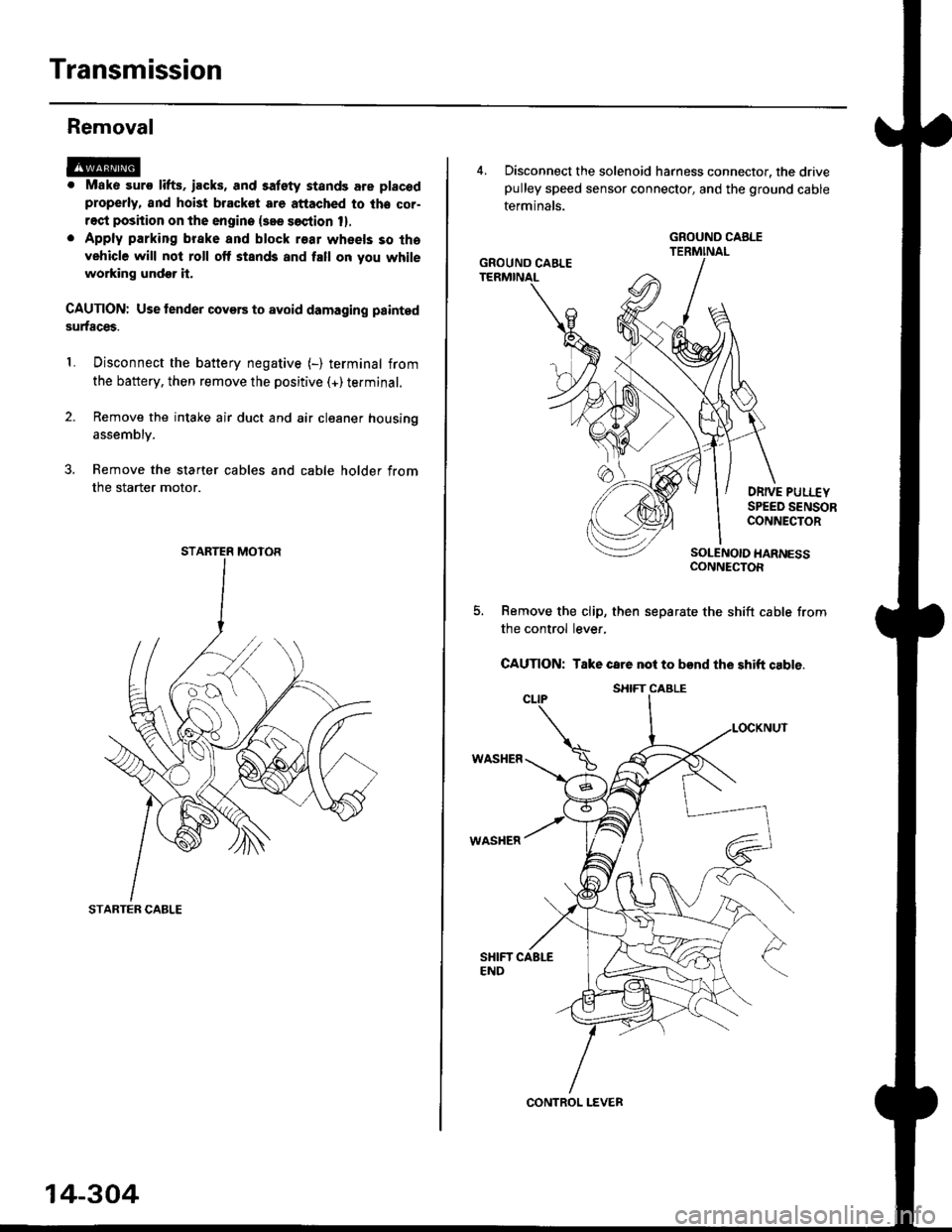
3. Remove the starter cables and cable holder from
the starter motor.
STARTER CABLE
STARTER MOTOR
14-304
4, Disconnect the solenoid harness connector, the drivepulley speed sensor connector, and the ground cable
terminals.
DRIVE PULI.-EYSPEED SENSORCONNECTOR
SOLENOIO HARNESSCONNECTOR
Remove the clip, then separate the shift cable from
the control lever,
CAUTION: Take care not to bend the shift cable.
WASHER
WASHER
GROUND CABLE
GROUND CAELE
CONTROL LEVER
S}IIFT CABLE
Page 983 of 2189

Transmission
Removal (cont'd)
10. Remove the cotte. pins and castle nuts, then separatethe ball joints from the lower arm (see section 1g).
SELF-LOCKING -=V,
NUT \Replace. oitupea rOax
Remove the right damper fork bolt, then separateright damper fork and damper.
Pry the right and left driveshafts out of the differen-tial.
Pull on the inboard joint to remove the right and leftdriveshafts (see section 16).
Tie plastic bags over the driveshaft ends.
NOTE: Coat all precision finished surfaces with cleanengine oil.
Remove the exhaust pipe A.
/\<,\CASTLE I{UT COTTERReplac6.
't 1.
't2.
tJ.
14.
q.
SELF.LOCKINGNUTReplace.
SELF.LOCKING NUTReplace.
14-306
EXHAUST PIPE A
19.
'16, Remove the right front mounvbracket,
ATF COOLER HOSE
17. Remove the ATF cooler hoses at the ATF coolerlines. Turn the ends of the ATF cooler hoses uo toprevent CVT fluid from flowing out, then plug theATF cooler hoses and lines,
NOTE: Check for any sign of leakage at the hosejoints.
18. Remove the engine stiffeners and the flywheel cover.
Remove the eight drive plate bolts one at time whilerotating the crankshaft pullev.
ENGINE STIFFENER
Page 1005 of 2189

Secondary Gear Shaft
25 x 35 mm Thrust Shim Selection
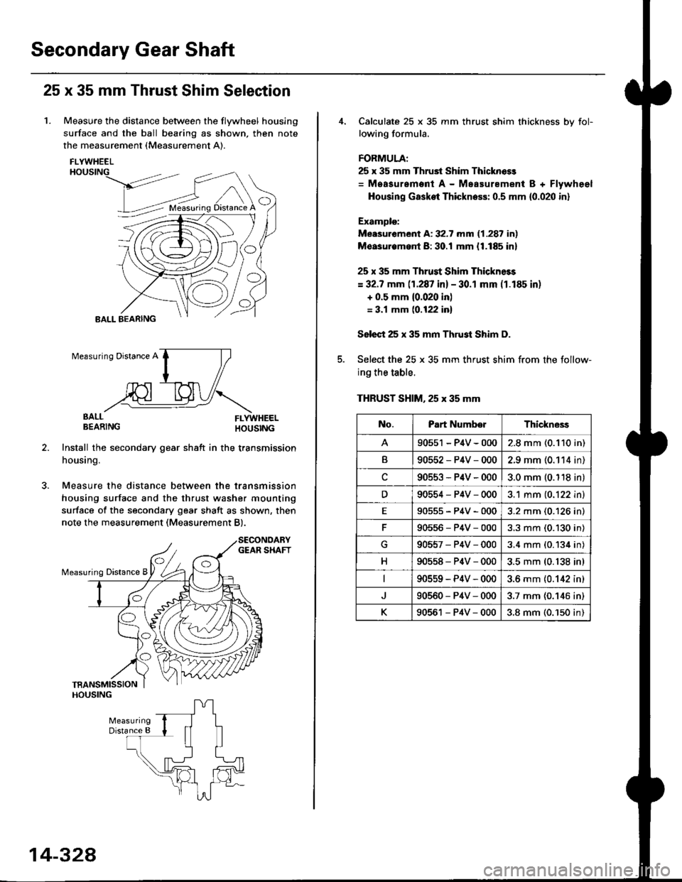
1. Measure the distance between the flywheel housing
surface and the ball bearing as shown, then note
the measurement (Measurement A).
FLYWHEELHOUSING
>dt?'
BALL BEARING
EALL FLYWHEELBEARING HOUSTNG
Install the secondary gear shatt in the transmission
housing.
Measure the distance between the transmission
housing surface and the thrust washer mounting
surface of the secondary gear shaft as shown, then
note the measurement (Measurement B).
O
Measuring Distance A
BALL
14-328
Calculate 25 x 35 mm thrust shim thickness bv fol-
lowing formula.
FORMULA;
25 x 35 mm Thrust Shim Thicknoss
= Measurement A - Measurement B + Flywheel
Housing Gasket Thickness: 0.5 mm {0.020 in}
Example:
Measurement A: 32.7 mm (1.287 in)
Moasurem.nt B: 30.! mm {1.185 in}
25 x 35 mm Thrust Shim Thickness
= 32.7 mm (1.287 in) - 30.1 mm (1.185 in)
+ 0.5 mm {0.020 in)
= 3.1 mm (0.122 inl
Select 25 x 35 mm Thrust Shim D.
Select the 25 x 35 mm thrust shim from the follow-
ing the table.
THRUST SHIM, 25 x 35 mm
No.Part NumberThickne3s
90551 - P4V - 0002.8 mm (0.110 in)
B90552-P4V-0002.9 mm (0.114 in)
c90553-P4V-0003.0 mm (0.118 in)
D90554-P4V-0003.1 mm (0.122 in)
E90555-P4V-0003.2 mm (0.126 in)
90556-P4V-0003.3 mm (0.130 in)
G90557-P4V-0003.4 mm (0.134 in)
H90558-P4V-0003.5 mm (0.138 in)
90559-P4V-0003.6 mm {0.142 in)
90560-P4V-0003.7 mm (0.146 in)
K90561 - P4V - 0003.8 mm (0.'150 in)
Page 1028 of 2189

Transmission
Gooler Flushing
@ To prevent iniury to face and eyes, alwayswear safety glasses or a tace shield when using thetransmission flusher.
NOTE: This procedure should be performed before rein-stalling the transmission.
'1. Check the tools and hoses for wear and cracks before
using. lf wear or cracks are found, reDlace the hoses
before using.
4.
Using the measuring cup. fill the tank with 2,1 ounces(approximately 2/3 full) of biodegradable flushingfluid (J35944 - 20). Do not substitute with any otherfluid. Follow the handling procedure on the fluidcontatner.
Secure the flusher filler cap, and pressurize the tankwith compressed air to between 5S0 - 829 kpa (5.6 -
8.45 kgf/cm'�, 80 - 120 psi).
NOTE: The air line should be equipped with a watertrap to ensure a dry air system,
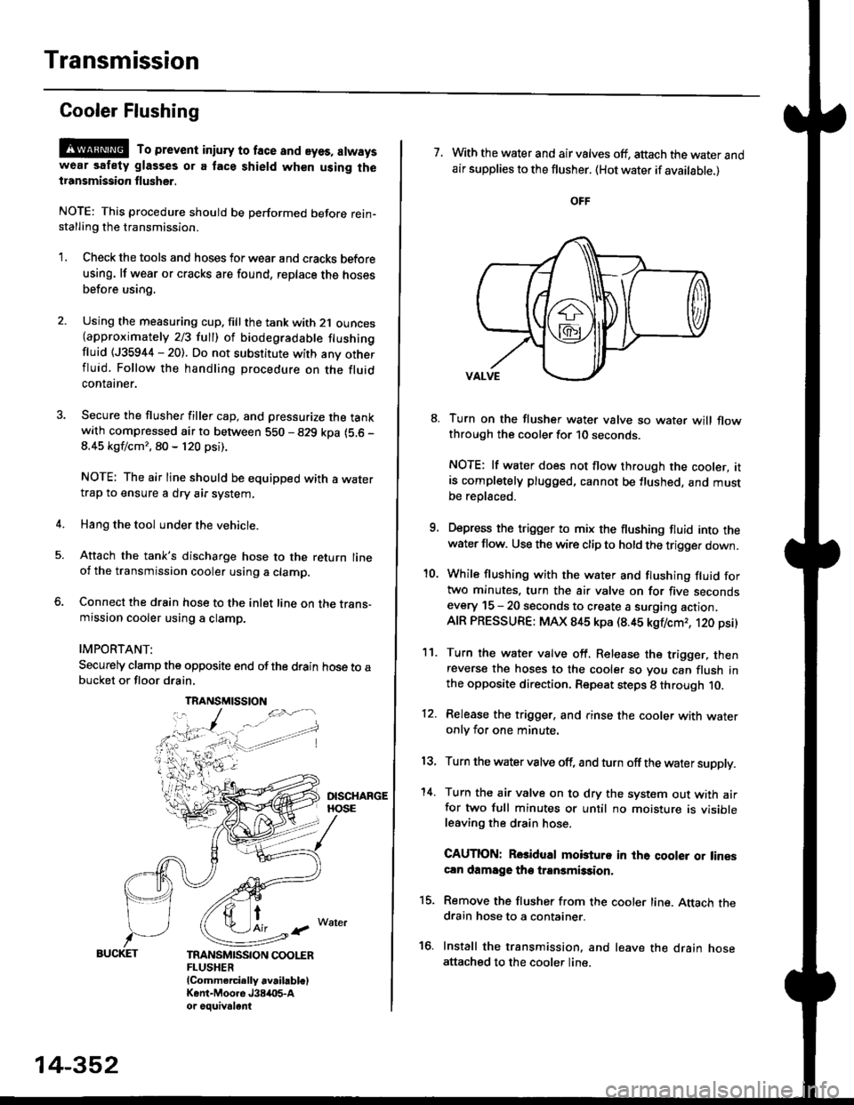
Hang the tool under the vehicle.
Attach the tank's discharge hose to the return lineoi the transmission cooler using a clamp.
Connect the drain hose to the inlet line on the trans-mission cooler using a clamp.
IMPORTANT:
Securely clamp the opposite end ofthe drain hose to abucket or floor drain,
t
TRANSMISSION COOLERFLUSHER{Commercially available)Kent-Moore J384O5-Aor oouivalent
TRANSMISSION
14-352
7. With the water and air valves off, attach the water andair supplies to the flusher. (Hot water if available.)
8. Turn on the flusher water valve so water will flowthrough the cooler for 10 seconds.
NOTE: lf water does not flow through the cooler, itis completely plugged, cannot be flushed, and mustbe replsced.
9. Depress the trigger to mix the flushing fluid into thewater flow. Use the wire clip to hold the trigger down.
'10. While flushing with the water and flushing fluid fortwo minutes. turn the air valve on for five secondsevery 15 - 20 seconds to create a surging action.AIR PRESSURE: MAX 845 kpa (8.45 kgflcmr, 120 psi)
11. Turn the water valve off. Release the trigger, thenreverse the hoses to the cooler so you can flush inthe opposite direction. Repeat steps 8 through 10.
12. Release the trigger. and rinse the cooler with wateronly for one minute.
13, Turn the water valve off, and turn off the water supply.
'14. Turn the air valve on to dry the system out with airfor two full minutes or until no moisture is visibleleaving the drain hose.
CAUTION: Rosidual mobturo in the qooler or linescln damage the transmission,
15. Remove the flusher from the cooler line. Attach thedrain hose to a container.
16. Install the transmission. and leave the drain hoseattached to the cooler line.
Page 1044 of 2189

lnboard Joint Side:
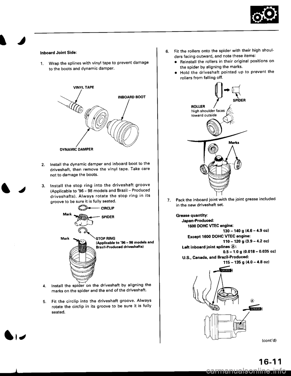
1, Wrap the splines with vinyl tape to prevent damage
to the boots and dynamic damPer.
TAPE
INBOARD BOOT
DYNAMIC DAMPER
Install the dynamic damper and inboard boot to the
driveshaft, then remove the vinyl tape. Take care
not to damage the boots.
Install the stop ring into the driveshaft groove
(Applicsble to '96 - 98 models and Brazil - Produced
driveshafts). Always rotate the stop ring in its
groove to be sure it is fully seated.
@--c't"t't
STOP RING(ApplicablG to'96- 98 modob and
Brrzil-Producrd drivoshaftrl
Install the spiiler on the driveshaft by aligning the
marks on the sDider and the end of the driveshaft.
Fit the circlip into the driveshaft groove. Always
rotate the circlip in its groove to be sure it is fully
seated.
VINYL
- -
/
-<@
lr;
6. Fit the rollers onto the spider with their high shoul-
ders facing outward, and note these items:
. Reinstall the rollers in their original positions on
the spider by aligning the marks
. Hold the driveshaft pointed up to prevent the
rollers from falling off.
Pack the inboard joint with the joint grease included
in the new driveshaft set.
Grease quantity:
Japan-Produced:
1600 DOHC VTEC ongine:
130 - 1/t0 g 14.6 - '[.9 oz)
Except 1600 DOHC VTEC angine:
110 - 120 I {3'9 - il'2 oz}
Left inboard ioint splines O:
0'5 - 1.0 s (0.018 - 0'035 oz)
U.S,, Canada, and Brazil'Produced:
115 - 135 g (40-4.8ozl
7.
6
-6.l
(cont'd)
16-1 1
High shoulder faces
Page 1047 of 2189
Driveshafts
17.
Reassembly (cont'dl
Unwind the boot band tool, and cut off the excess 5- 10 mm (0.2 - 0.4 in) from the clip.
5-10mm10.2 - 0.a inl
Secure the end of the boot band by tapping it downwith a hammer,
19. Installthe new set ring,
18.
Note these items after reassembly:. Make sure the band and clip does notanything and the band does not move.a Remove any grease remaining on thesurfaces.
interfere with
su rrou nding
16-14
Outboard Joint Sid.:
1. Wrap the splines with vinyl tape to prevent damageto the boot.
TPE tvDe:-. OUTBOARO BOOT ITPE)
BOOT BANDReplac€,
Rubber typ.:
Install the boot band and outboard boot, thenremove the vinyl tape. Take care not to damage theboot,
Install the stop ring into the driv€shaft groove.
DRIVESHAFT
>VINYL TAPE
VINYL TAPE
Page 1048 of 2189
J)
4. lnsert the driveshaft into the outboard joint until the
stop ring is close on the ioint.
DRIVESHAFT
To completely seat the outboard joint, pick up the
driveshaft and joint, and drop them from about 10
cm (4 to 5 inches) onto a hard surface. Do not use a
hammer as excessive force may damage the drive-
shaft.
16-15
J
6. Check the alignment of the paint mark with the out-
board joint end.
Pack the outboard joint with the joint grease includsd
in th€ new ioint boot set.
Gleaso quanlity
U.S., canada, and Brazil'Ploducod:
115 - 135 g {4.0 - 4.8 oz}
Japan-Producod:
161X, DOHC VTEC angino:
Rubbor boot: 90 - 100 g 13.2 - 3.5 oz)
TPE boot: 1tl6 - 115 I {3'7 - tl'l oz}
Excapt 1000 DOHC VTEC engine:
Rubbel boot: 70 - 80 g l.2.5 - 2.8 ozl
TPE boot: 95 - 105 g {3.4- 3.7 oz}
7.
DRIVESHAFT
(cont'd)