Page 608 of 2189

Synchro Ring, Gear
Inspection
1. Inspect the synchro ring and gear.
A: Inspect the inside of the synchro ring for wear.
B: Inspect the synchro sleeve teeth and matching
teeth on the synchro ring for wear (rounded off).
r- /-\
oioi *-o*
C: Inspect the synchro sleeve teeth and matching
teeth on the gear for wear (rounded off).
,
UtJGOOO WORN
D: Inspect the gear hub thrust surface for wear.
E: Inspect the cone surface for wear and roughness.
Fr Inspect the teeth on all gears for uneven wear,
scoring, galling, and cracks.
2. Coat the cone surface of the gear with oil. and place
the synchro ring on the matching gear. Rotate the
synchro ring. making sure that it does not slip.
Measure the clearance between the synchro ring
and gear all the way around.
NOTE: Hold the synchro ring against the gear evenly
while measuring the clearance.
Synchro Ring-to-Gear Clearance
Standard: 0.73 - 1.18 mm {0.029 - 0.046 in}
Service Limit 0.4 mm {0.02 in)
lf the clearance is less than the service limit, replace
the synchro ring and synchro cone.
SYNCHRO
SYNCHRO
\a
r/
13-28
Page 612 of 2189
Differential
Thrust Shim Adjustment
1. Install the differential assembly, making sure it bot-toms in the clutch housing, using the special tool asshown.
DRIVER, 40 mm LD.07746 0030100
Install the thrust shim.
NOTE: Install the same size thrust shim that wasremoved.
Y
Install the transmission housing (see page l3-41).
NOTE: Do not apply liquid gasket to the mating sur-face of the clutch housing.
Tighten the transmission housing attaching bolts(see page 13-42).
I x 1,25 mm
27 N.m (2.8 kgt'm, 20 lbf'ft}
Use the special tool to bottom the differential assem-
bly in the clutch housing.
tJ
6. Measure clearance between thrust shim
ing outer race in transmission housing.
and bear-
13-32
Page 613 of 2189

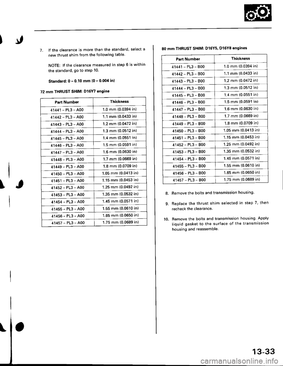
7. lf the clearance is more than the standard, select a
new thrust shim from the following table
NOTE: It the clearance measured in step 6 is within
the standard. go to step 10.
Standard: 0 - 0.10 mm l0 - 0.00/t inl
72 mm THRUST SHIM: D16Y7 engin€
\
Part NumberThickness
41441 - PL3 - A001.0 mm (0.0394 in)
41442-PL3-A00'1 .1 mm {0.0433 in)
41443-PL3-A001.2 mm {0.0472 in)
41444-PL3-A001.3 mm (0.0512 in)
41445-PL3-A001.4 mm (0.0551 in)
41446-PL3-A001.5 mm (0.0591 in)
41447-PL3-A001.6 mm (0.0630 in)
41448-PL3-A001.7 mm (0.0669 in)
4r449-PL3-A001.8 mm (0.0709 in)
41450-PL3-A001.05 mm {0.0413 in)
41451-PL3-A001.15 mm (0.0453 in)
41452-PL3-A001.25 mm (0.0492 in)
41453-PL3-A001.35 mm (0.0532 in)
41454-PL3-A00'1.45 mm (0.057'l in)
41455-PL3-A001.55 mm (0.0610 in)
41456-PL3-A001.65 mm (0.0650 in)
41457-PL3-A001.75 mm (0.0689 in)
80 mm THBUST SHIM: D16Y5. D16Y8 engines
Remove the bolts and transmission housing.
Replace the thrust shim selected in step 7, then
recheck the clearance.
Remove the bolts and transmission housing. Apply
liquid gasket to the surface of the transmission
housing and reassemble
8.
9.
10.
Part NumbelThickness
41441 - PL3 - B001.0 mm (0.0394 in)
41442-PL3-8001.1 mm (0.0433 in)
41443-PL3-8001.2 mm (0.0472 in)
41444-PL3-8001.3 mm (0.0512 inl
41445-PL3-8001.4 mm (0.0551 in)
41446-PL3-8001.5 mm (0.0591In)
41447-PL3-8001.6 mm (0.0630 in)
4r 448 - PL3 - 8001.7 mm (0.0669 in)
4 t449 - PL3 - 8001.8 mm (0.0709 in)
41450-PL3-800'1.05 mm (0.0413 in)
41451 - PL3 - 800'1.15 mm (0.0453 in)
41452-PL3-8001.25 mm (0.0492 in)
41453-PL3-B001.35 mm (0.0532 in)
41454-PL3-B001.45 mm (0.0571 in)
41455-PL3-B001.55 mm (0.0610 in)
41456-PL3-8001.65 mm (0.0650 in)
41457-PL3-8001.75 mm {0.0689 in)
Page 616 of 2189

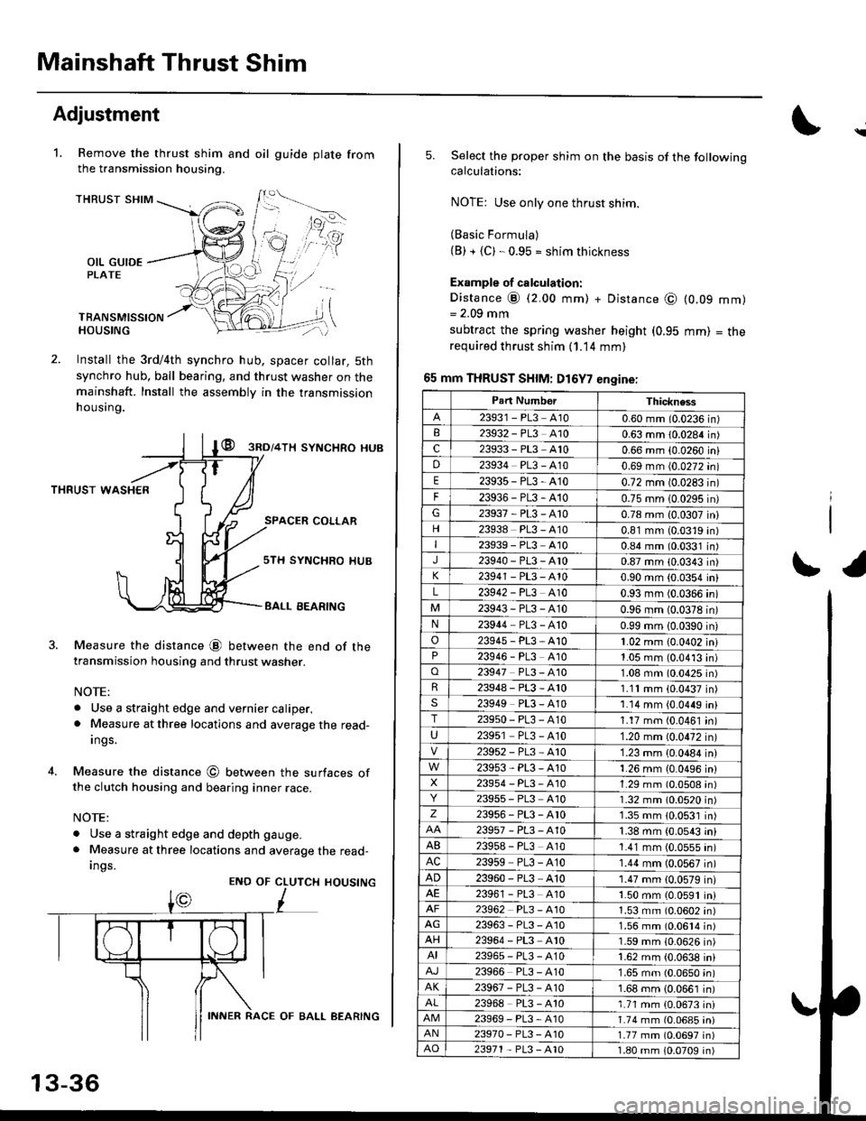
Mainshaft Thrust Shim
Adjustment
Remove the thrust shim and oil
the transmission housing.
1.gu ide plate from
THRUST SHIM
OIL GUIDEPLATE
TBANSMISSIONHOUSING
Install the 3rd/4th synchro hub, spacer collar, 5th
synchro hub, ball bearing, and thrust washer on themainshaft. Install the assembly in the transmission
h ousing.
@ gnol+lx syNcHRo HUB
THRUST WASHER
SPACER COLLAR
4.
Measure the distance @ between the end of thetransmission housing and thrust washer.
NOTE:
. Use a straight edge and vernier caliper.. Measure at three locations and average the read-
Ings.
Measure the distance @ between the surfaces ofthe clutch housing and bearing inner race.
NOTE:
. Use a straight edge and depth gauge.
. Measure at three locations and average the read-
Ings.
sTH SYNCHRO IIUB
BALL EEARING
CLUTCH
L
HOUSINGENO OF
13-36
INNER RACE OF BALL AEARING
\
5.Select the proper shim on the basis of the followingcalculations:
NOTE: Use only one thrust shim.
(Basic Formula)(B) + {C). 0.95 = shim thickness
Example of calculation:
Distance @ (2.00 mm) + Distance @= 2.09 mm
subtract the spring washer height (0.95
required thrust shim (1.14 mm)
65 mm THRUST SHIM: D16Y7 engine:
(0.09
mm)
mm)
= tne
r1
Part NumborThickness
23931 - PL3 A100.60 mm (0.0236 in)23932 - PL3 A100.63 mm 10.0284 in)c23933 - PL3 A100.66 mm {0.0260 iniD23934 PL3 - A100.69 mm (0.0272 in)
E23935-PL3-4100.72 mm 10.0283 in)
F23936-PL3-4100.75 mm 10.0295 in)G23937-PL3-A100.78 mm {0.0307 in}
23938 PL3 - A100.81 mm (0.0319 in)I23939 - PL3 At00.84 mm (0.0331 in)J23940-PL3-Ar00.87 mm (0.0343 in)
23941 - PL3 - A100.90 mm (0.0354 in)
L23942 - PL3 A100.93 mm (0.0366 in)
23943-PL3-A100.96 mm (0.0378 in)N23944 PL3 - A100.99 mm 10.0390 in)
o23945-PL3-A101.02 mm {0.0402 in}23946 - PL3 A101.05 mm (0.0413 in)o23947 PL3 - 4101.08 mm (0.0425 in)R23948-PL3-A101.11mm (0.0437 in)s23949 PL3 - A101.14 mm {0.0449 in}T23950-PL3-A101.17 mm (0.0461 in)
U23951 PL3 - A101.20 mm (0.0472 in)
23952-PL3-Ar01.23 mm {0.0484 in)
23953-PL3-A101.26 mm {0.0496 in}X23954 - P13, A101.29 mm (0.0508 in)23955 - PL3 A101.32 mm (0.0520 in)z23956-PL3-Ar01.35 mm {0.0531 in)
23957-PL3-A101.38 mm (0.0543 in)
AB239s8 - PL3 A101.41 mm (0.0555 in)AC23959 PL3 - A101.44 mm (0.0567 in)
AD23960 - PL3 A101.47 mm (0.0579 in)23961 - PL3 4101.50 mm (0.0591 in)23962 PL3 - A101.53 mm (0.0602 in)AG23963-PL3-4101.56 mm (0.0614 in)AH23964 - PL3 A101.59 mm (0.0626 in)AI23965-PL3-A101.62 mm {0.0638 in)
23966 PL3 - A101.65 mm (0.0650 in)AK23967-PL3-A101.68 mm {0.0661 in)
23968 PL3 - A101.71 mm {0.0673 in)23969-PL3-A101.74 mm (0.06a5 iniAN23970- PL3 -A101.77 mm (0.0697 in)AO23971 - PL3 - A101.80 mm 10.0709 in)
Page 618 of 2189

Mainshaft Thrust ShimI
I
Adjustment (cont'dl
b.Attach the mainshaft holder to the mainshaft asfollows:
NOTEI
. Back-out the mainshaft holder bolt and loosen
the two hex bolts.
. Fit the holder over the mainshaft so its lip istoward the transmission.
. Align the mainshaft holder's lip around thegroove at the inside of the mainshaft splines,then tighten the hex bolts.
MAINSHAFT HOLOERBOLT
MAINSIIAFTHOLDER07GAJ-PG20110
d.
Seat the mainshaft fully by tapping on the end witha plastic hammer.
Thread the mainshaft holder bolt in until it just
contacts the wide surface of the mainshaft base.
u
e. Zero a dial gauge on the end ofthe mainshaft.
MAINSHAFT HOLDER07cAJ_PG20110
Turn the mainshaft holder bolt clockwise: stop turn,ing when the dial gange has reached its maximummovement. The reading on the dial gauge is theamount of mainshaft end olav.
CAUTION: Turning the mainshaft holder bolt morethan 60 degre€s after the needle ot the dial gauge
stops moving may damage the iransmission.
lf the reading is within the standard. the clearance iscorrecl.
lf the reading is not within the standard, recheck theshim thickness.
Standard: 0.11 - 0.18 mm {0.00it - 0.007 in}
t.
\,J
Page 621 of 2189

17. Instali the oil gutter Plate.
Install the oil guide plate and thrust shim on the
transmission housing.
Apply Iiquid gasket to the surface of the transmis-
sion housing mating with the clutch housing as
shown.
NOTE:
. Use liquid gasket {P/N 08718 - 0001 or
08718 - 0003).
. Remove the dirty oil fromthesealing surface.
. lf 5 minutes have passed after applying liquid
gasket, reapply it and assemble the housings.
. Allow it to cure at least 20 minutes after assem-
bly before filling the transmission with oil.
18.
19.
\
OIL GUTTER PTATE
TRANSMISSION HOUSING
Liquid gasket
20.lnstall the dowel pins and the transmission housing.
Lower the transmission housing with the snap ring
pliers, and set the snap ring into the groove of the
countershaft bearing.
NOTE: Check that the snap ring is securely seated
in the groove of the countershaft bearing
32 mm SEALING EOLT25 N.m (2.5 kgf.m, 18lbf.ftl
4.6 -8.3 mm10.14-0.33 inl
Install the 32 mm sealing bolt.
NOTE: Apply liquid gasket (P/N 08718 - 0001
08718 - 0003) to the threads.
(cont'd)
22.
13-41
Page 625 of 2189

S4C Model ('99 - 00 2-door Si, SiR)
Manual Transmission
Special Tools ............' 13-46
Maintenance
Transmission Oi1 ...................'.......... 13-47
Back-up Light Switch
Repfacement ...""" 13'47
Transmission Assembly
Removal ......'.......... 13-/tB
lnstallation ............. 13-52
lllustrated lndex ................................... 13-54
Transmission Housing
Removal ................. 13-55
Beverse Shift Holder, Reverse ldler Gear
Clearance lnspection ...................".. 13-57
Removal ................. 13-58
Change Holder Assembly
Clearance lnspection .................".... 13-59
Removal ....,,........... 13-61
Disassembly/Reassembly ............... 1 3-62
Mainshaft, Countershaft, Shift Fork
Removal ................. 13-63
Shift Rod
Removal .........."'.... 13-64
Shift Fork Assembly
lndex ................ ...... 13-65
Clearance lnspection .............'......... 13'66
Mainshaft Assembly
lndex ............"" ...... 13-67
Clearance lnspection ....................... 13-68
Disassembly .......... 13-71
fnspection '."'.......', 13'72
Reassembly .......'... 13-73
Countershaft Assembly
fndex ................ "....13-71
Glearance Inspection'......'...........'... 1 3'75
Disassembly .......... 13-76
fnspection .'............13'77
Reassembly "......... 13'78
Synchro Sleeve, Synchro Hub
Inspection .............. 13'8C
Installation ............. 13-80
Synchro Ring, Gear
Inspection .'............ 13-81
Differential
lndex ................ ...... 13-82
Backlash Inspection ..."..........."'...... 1 3-82
Final Driven Gear Replacement ...... 13-83
Bearing Replacement ....."'.......""'.. 13-83
Thrust Shim Adiustment ......""'..... 13-84
Clutch Housing Bearing
Replacement ..'...... 13-86
Mainshaft Thrust Glearance
Adiustment '.........'. 13-88
Transmission
Reassembly ."'....... 13-91
Oil Seals
Replacement ..'...... 13-96
Gearshift Mechanism
Overhaul ................ 13-97
\
Page 630 of 2189
Transmission Assembly
Removal(cont'd)
14. Remove the driveshafts and the intermediate shaft(see section 16).
NOTE: Coat all precision the finished surfaces with
clean engine oil or grease. Tie plastic bags over the
driveshaft ends,
Remove the bolt, then disconnect the change elden-
sion.
Remove the clip and the spring pin, then disconnectthe change rod.
8x22mmSPRING PINCLIP Replace.
15.
13-50
17. Remove the front and the rear engine stiffensrs.
18. Remove the clutch cover.
CLUTCH COVER
6x1.0mm12 N.m (1.2 kg{.m,9 tbf.ftl
x 'l .25 mm
tJ
24 N.m {2.4 kgt m,17 rbt ftl