1997 HONDA CIVIC Dor connector
[x] Cancel search: Dor connectorPage 360 of 2189

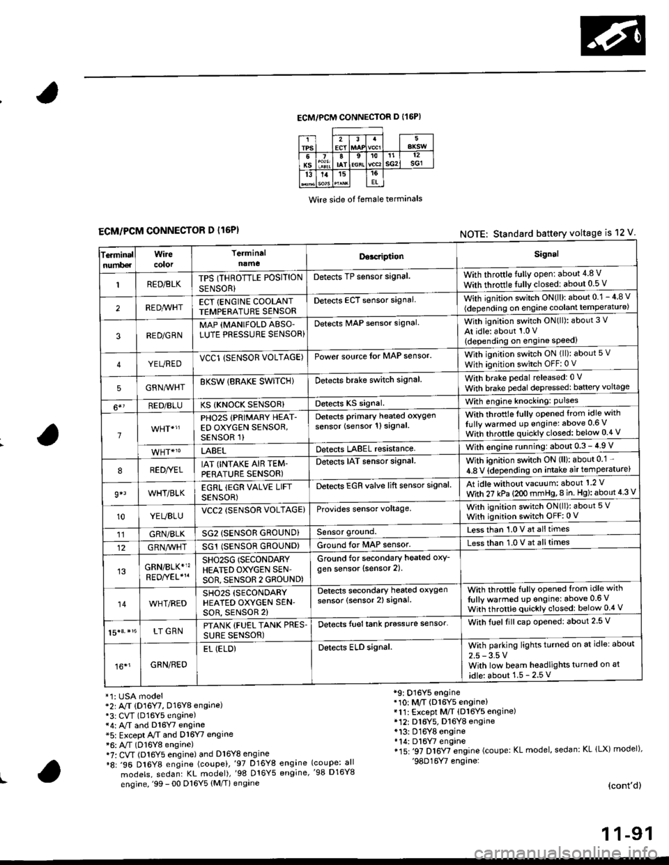
ECM/PCM CONNECTOR D I16P)
Wire side ot female terminals
ECM/PCM CONNECTOR D l16P)NOTE: Standard battery voltage is 12 V
Te.minalnumb€r
Wirecolor
Terminaln!meDor.riptionSignal
RED/BLKTPS (THROTTLE POSITION
SENSOR}
Detects TP sensor signal.With throttle fully open: about 4.8 V
With throttle fully closedl about 0.5 V
REDA/VHTECT {ENGINE COOLANTTEMPERATURE SENSORDetects ECT sensor signalWith ignition switch ON{ll): about 0.1 - 4 8 v
(depending on engine coolant lempe ratu re)
3RED/G RNMAP {MANIFOLD ABSO'LUTE PRESSURE SENSOR}Detects MAP sensor signal.With ignition switch ON(ll): about 3 V
At idle: about 1.0 V
{depending on engine speed)
YEUREDVCCl (SENSOR VOLTAGE)Power source lor MAP sensor.With ignition switch ON (ll): about 5 v
With ignition switch OFF: 0 V
5GRNMHTBKSW {BRAKE SWITCHIDetects brake switch signalWith brake pedal released: 0 v
With brake pedal depressed: baftery voltage
6*?RED/BLUKS {KNOCK SENSOR}Detects KS signal.With engine knocking: Pulses
1
PHO2S (PRIMARY HEAT-ED OXYGEN SENSOR,SENSOR 1)
Detects Primary heated oxygen
sensor (sensor 1l signal
With throttle fullv opened from idle with
Iully warmod up engine: above 0.6 V
With throttle quickly closed: below 0.4 v
LABELDetects LABEL resistanceWith engine r!nning:about 0.3 - 4.9 V
8RED//ELIAT (INTAKE AIR TEM-PERATURE SENSOR)
Detects IAT sensor signal.With ignition switch ON (ll): about 0 1 -
4.8 V {depending on intake air temperature)
9*lWHT/BLKEGRL iEGR VALVE LIFT
SENSOR)
Detects EGR valve lift sensor signalAt idle without vacuum: about'1 2 V
With 27 kPa (2OO mmHg,8 in. Hg): about 4 3 V
10YEUBLUVCC2 (SENSOR VOLTAGE)Provides sensor voltage,With ignition switch ON(ll): about 5 V
With ignition switch OFF:0 V
11GRN/BLKSG2 (SENSOR GROUND}Sensor ground.Less than 1.0 V at alltimes
12G RN,4/1r'HTSG1 (SENSOR GROUND)Ground for MAP sensor.Less than 1.0 V at alltimes
GRN/BLK*1?SHO25G (SECONDARY
HEATED OXYGEN SEN'
SOR, SENSOR 2 GROUND)
Ground for secondary heated oxy-
gen sensor (sensor 2).
14WHT/REDSH02S (SECONDARY
HEATED OXYGEN SEN'soR, sENsoR 2)
Detects secondary heated oxygen
sensor (sensor 2) signal.With throftle fully opened lrom idle with
fully warmed up engine: above 0.6 V
With throttle quickly closed: below 0.4 V
15|3. *15LT GRNPTANK {FUEL TANK PRES.
SURE SENSOR)
Detects fueltank prgssure sensor'With fuelfill caD opened: about 2.5 V
16*1GRN/RED
EL (ELD)Detects ELD signal.With parking lights turned on at idle: about
2.5 - 3.5 VWith low beam headlights turned on at
idle: about 1.5 - 2.5 V
*1: USA model*2r A/T (D16Y7, D16Y8 engine)*3: CVT (D16Y5 engane)*4: A,/T and Dl6Y7 engine*5: Except A/T and D16Y7 engine*6: A"/T (D16Y8 engine)i7: CVT (Dl6Y5 engine) and Dl6Y8 engine*8: .96 D16Y8 engine (coupei,'97 D16Y8 engine
models, sedanr KL model),'98 016Y5 engine,
engine, '99 - 00 D16Y5 (M/T) engine
*9: D16Y5 engine*10: M/T (D16Y5 engine)*11: Except M/T (Dl6Y5 engine)* 12r D16Y5. D16YB engine*13: D16Y8 engine*14: Dl6W engine*15: '97 D16Y7 engine (coupe: KL model, sedan: KL lLX) model),'98D16Y7 engine:(coupe: all'98 D16Y8
(cont'd)
1 1-91
Page 364 of 2189

ECM/PCM CONNECTOR O {16P)
Wire side ol temale terminalsECM/PCM CONNECTOR D {16P)
(D16Y7, D16Y8 enginelNOTE: Standard battery voltage is 12 V.
L
.1 A/J (Dl6Y7, Dr6Y8 engine)
(cont'd)
1 1-95
5i!ml
YELLCA (LOCK.UPCON]ROLSOLENOID VALVE A)Orivos look-up controlsol€noid wlv€ a.With lock-up ON: httery vollageWith lock-up OFFi 0 V
GRN,M/HT
SHB {SHIFT CONTFOLSOLENOIO VALVE B)Drivos sh ift cont.ol solanoid valv6 Bln E posnion, in 1st lnd 2nd eoat ,n E E pos'tion:Battsry voltagoInElposirion. in 3rd seat in pd, El in.th sear in
l_�d polition: o v
3''GRN/BLKLC8 (IOCK UP CONTBOLSOLENOID VALVE B)Drivs locl up conttol sol€noid v6lv€ Bwhen fulllock-up: Banory vollagaWnh naf locl-uP: Pulsing si9n6l
5',BLK/YELVSSOI (BATTEsYVOLTAGEFOB SOLENOID VALVE)Powe. sourc€ ol solGnoid valvewirh ignirion sitch ON (ll): battory voltaoeWirh ignnion switch OFF:0 v
ATPR (AT GEAR POSITIONswrTcH)Detecrs Ay'T g6a. position switch signal.In any olh€r position: APProx. 10 V
8LU/YEL
SHA iSHIFI CONTROLSOLENOIDVALVE A)Oriv€6 sh ift conirol sol€noid valve A.ln tr,tr position, in 2nd €nd 3rd sear in lpd, &lposirion: Batt€ry vollsgo;n 1d soar in E, E position, in.ih se6r in E
PNKATPO3 (AT GEAR POSITIONSWITCH)Oot6cts Ay'T S6.r poeirioo switch siSnalIn Enyoth.r position: APPror, t0 v
9''YELATPD4 {AT GEAE POSITIONswrTcH)Oorocts A/I gs8r position switch signal.In any oth6t position:APProx 5 V
BIUNC (COUNTE RSHAFT SPEEDSENSOB)DetocB counr€.shaft sp66d $osr sig.alsD€p€nding on v6hicls 8pe€d;Pul.ins signalWh6n v€hicls i5 ltoPPsd:0 v
REONM (MAINSHAFTSPEED SEN.soR)O€l€cts mainshalt sp€€d 3.nsor 3ign.lsWi$ engino rLrnningl PUls6s
NMSG {MAINSHAFT SPEEOSENSOR GFOUNO)Groundfo, mainshaft sp@d sensor.
13''!T GFNATPNP {AT GEAF POSITIONswrrcH)oetscts A/T 96ar pGitaon swhch signalIn par* or n6ulral:0 VIn sny olhd po3ition: APProx l0V
BLUATPz {AT GEAE POSITIONswrTcHlDor€cis !y'T gos. posilion swilch signal.In any oth6r Position: APProx, 10 V
16''GANNCSG {COUNTEBSHAFT SPEEDSENSOE GROUND)Ground lor countershaii sp€3d s6nsor.
r lo
Page 391 of 2189

PGM-FI System
Manifold Absolute Pressure (MAPI Sensor
11-122
('99 - 00 Models except D16YS engine with M/T) (contd)
The scan tool indicates Diagnostic Trouble Code (DTC) P0108: A high voltage flow vacuum) problem in theManifold Absolute Pfessure (MAp) sensor,
MAP SENSOR 3P CONNECTOR (C111I
MAPIRED/GRNI
Wire side of female terminals
vcclIYEL/RED)
ECM/PCM CONNECTOR C (31PI
JUMPER WIRE
Wire side of female terminals
Tho MIL has boon rcDortod on.DTC ml 08 b stolod.
Problem verification:'1. Start the engine. Hold theengine at 3,000 rpm with noload (in Park or neutral) untilthe radiator fan comes on, thenlet it idle.2. Check the MAP with the scantoot,
Intormittent f.ilu.e, rystom is OXat thi! time. Chock tor poor con-n6ction3 or looso wirea at C111(MAP 3en.or) and tho ECM/PC-M.
ls 101 kPa (760 mmHg.30in.Hg) or higher indicated?
Check for an open in the MAPaon5('r:1. Turn the ignalion switch OFF.2. Disconnect the MAP sensor3P connector.3. Install a jumper wire betwesnthe MAP sensor 3P conn6ctorterminals No.3 and No.2.4. Turn the ignition switch ON {ll).5. Check the MAP with the scantool.
ls 101 kPa (760 mmHg, 30in.Hg) or higher indicated?
Check fo. an opcn in wiro (SGlline):1. Removo the jumper wire.2. Measure voltage between theMAP sonsor 3P connector terminals No. 1 and No.2.
Roprir opon in tha wiJo bctwoenthc ECM/FCM (C7l rnd the MApsonln t.
ls there approx. 5 V?
Chsck for an open in tho wi.e{MAP lino}:1. Turn the ignition switch OFF.2. Install a jumper wire on theECM/PCM connectors betweenC7 and C17.3. Turn the ignition switch ON (ll).4. Check the MAP with the scantool,
Repair op€n in the wir6a bstwoontho ECM/FCM (C171 and rh6 MApscnltoa.
ls 101 kPa (760 mmHg, 30in.Hg) or higher indicated?
Substituto a known-good ECM/PCM and rechcck, It normal MAPis indiceted. r.place tho originalECM/PCM.
JUMPER WIRE
--
Page 415 of 2189

PGM-FI System
Itil-"w Heated Oxygen Sensor (primary HO2S) (sensor 1l(Dl6Y5 engine with M/Tl
The scan tool indicates Diagnostic Trouble Code (DTC) p1162: A malfunction in the primary Heated OxygenSensor (Primary HO2S) (Sensor 1) circutt.
Doscription
The Primary Heated orygen sensor (Primary Ho2s) {sensor 1) operates over a wide airlfuel range. The primary Ho2S(Sensor 1) is installed in the exhaust manifold.
SEI{SORELEMENT
SENSORTERMINALS
ECM CONNECTOR C (31PIPRIMARY HO2S(SENSOR 1)8PCONNECTOR {Clir5)
female terminalsof femaleterminals
NOTE: lf DTC Pl162 is stored at the same time as DTC Pl167, troubteshoot DTC p1162 first, then recheck for DTC p1167.
(To page 11-147)
- lh6 MIL hes b6on reDorted on.- DTCPl162 ir 3tored.
Problom v6rificationi1. Do the ECM Reset Procedure.2. Start the engine.3. Wait at least tlvo minutes.
Test drive tor several miles withthe transmission in 3rd gear. Holdthe engine speed at 1,500 rpm.
ls DTC P1162 indicatod?
Intermittent tailuro, systom is OKat this timo. Check tor poor con-nections or loose wires at C145(Plimr.y HO2S, Senso. t) andECM,
ls DTC P1162 indicated?
Chock for an open in the wire(lP+ lins):1. Turn the ignition switch OFF.2. Disconnect ECM connector C{31P) from the ECM.3. Disconnect the 8P connectorfrom the Primary HO2S {Sen-sor 1).4. Check for continuity betweenthe Primary HO2S (Sensor 1)8P connector terminal No. 7and ECM connector terminalc23.
Repair open in the wire betwaonECM (C231 end Prim.ry HO2Slsen3or l).
Inspect lor poor terminal to termi-nal contact at the Primary HO2Slsensor 'l I connoctor and ECM.It terminal contect is OK, roplacelh6 Primrry HO2S {Sensor 1}.
11-146
Page 422 of 2189

Secondary Heated Oxygen Sensor {secondary HO2S) (Sensor 2l
*'t : D16Y8 engine*2:'99 - O0 m;dels except D16Y5 engine with M//T
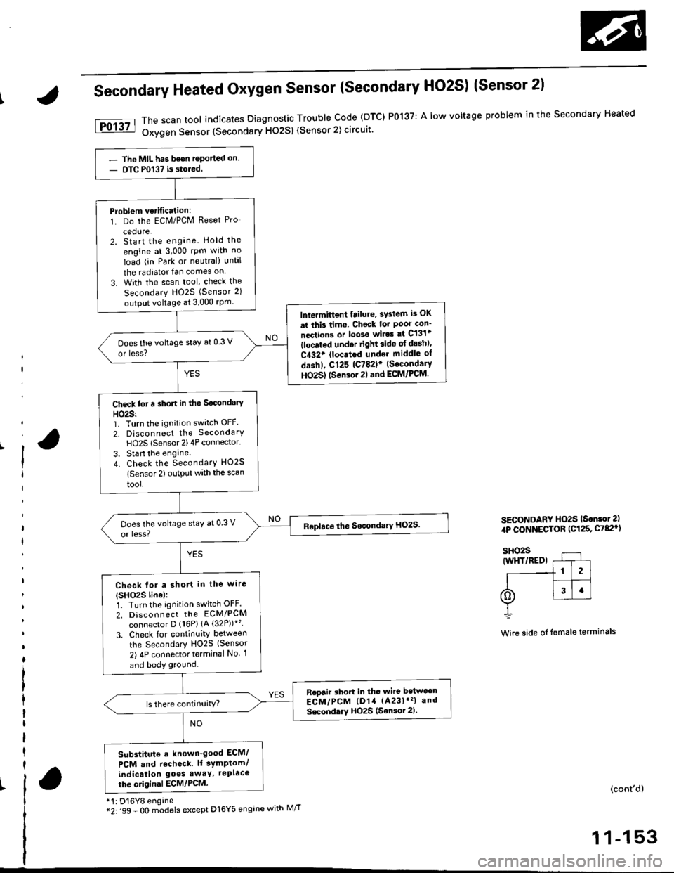
The scan tool indicates Diagnostic Trouble Code (DTC) P0137: A low voltage problem in the Secondary Heated
Oxygen Sensor (Secondary HO2S) (Sensor 2) circuit'
SECONDARY HO2S ls.n.ot 2),rP CONNECTOR (C125, C782')
Wire side oI temale terminals
(cont'd)
1 1-153
- Tho MIL has been reported on- DTC P0137 is stored.
Problem verification:1. Do the ECM/PCM Reset Pro
cedure.2. Start the engine. Hold the
engine at 3,000 rpm wlth no
load (in Park or neutral) until
the radiator fan comes on
3. With the scan tool, check the
Secondary HO2S (Sensor 2)
output voltage at 3,000 rPm
lntermittent frilure, sYdem is OK
at this tim6. Check for Poor con'
nections or loolo wir.3 at C131t(locatod undor right.ido of desh)'
C432. {located under middle of
dashl, cl25 lc782lr {SecondaryHO2S) tsensor 2l .nd ECM/PCM.
Does the voltage staY at 0.3 V
or less?
Ch6ck tot a sho.t in the S€condery
HO23:'1. Turn the ignition switch OFF.
2, Disconnect the SecondarY
HO2S lSensor 2)4P connector.
3. Start the engine.
4. Check the SecondarY HO2S
lsensor 2) output with the scan
tool,
Check tor a short in the wire
{SHO2S linel:1. Turn the ignition switch OFF.
2. Discon n ect tho EcM/PCM
connector D {16P) {A (32P))*'�
3. Check for continuity between
the SecondarY H02S (Sensor
2) 4P connector terminal No 1
and body ground.
R€pair short in tho wire bstwoen
ECM/PCM lD14 (A231*'�| and
Secondarv HOzS (Sensor 2).
Substitute a known-good ECM/
PCM and recheck lf 3ymptom/
indicalion go€s awaY, tePltco
the oiigin.l ECM/PCM.
Page 445 of 2189

PGM-FI System
Vehicle Speed Sensor (VSSI ('96 - 98 Models,'99 - 00 D16Y5 engine with M/Tl
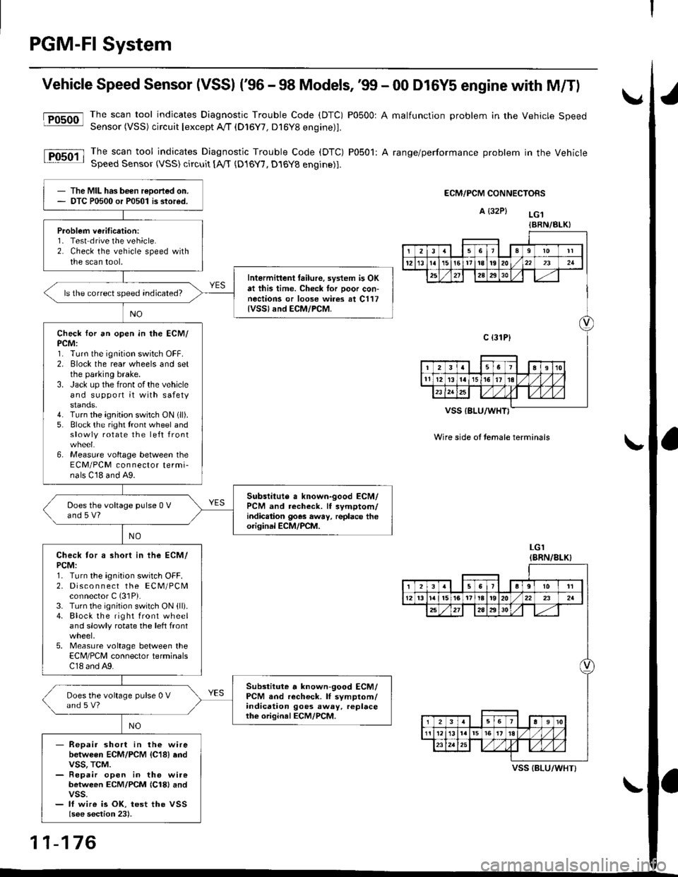
@The scan tool indicates Diagnostic Trouble Code (DTC) P0500: A malfunction problem in the Vehicle SpeedSensor (VSS) circuit Iexcept A!/T (D16Y7, D16Y8 engine)1.
The scan tool indicates Diagnostic Trouble Code (DTC) P0501: A range/performance problem in the VehicleSpeed Sensor (VSS) circuit [A,rT {D16Y7, D16Y8 engine)].
ECM/PCM CONNECTORS
A {32P} LG.t
VSS IBLU/WHT}
Wire side ot temale terminals
LGI(BRN/8LK}
The MIL has been reDorted on.DTC P0500 or P0501 is stored.
Problem verification:1- Test drive the vehicle.2. Check the vehicle speed withthe scan tool.
Intermittent tailure, system is OKat this time. Check tor Door con-nections or loose wires at C117{VSSland ECM/PCM.
ls the correct speed indicated?
Check for an open in the ECM/PCM:1. Turn the ignition switch OFF.2. Elock the rear wheels and setthe parking brake.3. Jack up the front of the vehicleand support it with safetystands.4. Turn the ignition switch ON (ll).
5. Block the right tront wheel andslowly rotate the left front
6, Measure voltage between theECM/PCM connector termi-nals C18 and A9.
Subslitute a known-good ECM/PCM and recheck. lf symptom/indic.tion goes away, replace theorisinal ECM/PCM.
Does the voltage pulse 0 Vand 5 V?
Check tor a short in ihe ECM/PCM:1. Turn the ignition switch OFF.2. Disco n n ect the ECM/PCMconnector C (31P).
3. Turn the ignition switch ON {ll).4. Block the right front wheeland slowly rotate the left front
5. Measure voltage between theECM/PCM connector terminalsC18 and A9.
Substitute a known-good ECM/PCM and recheck. lI symptom/indication goes away. replacethe original ECM/PCM.
Does the voltage pulse 0 Vand s V?
- Repair short in the wirebetwGen ECM/PCM {C18} endvss, TcM.- Repair open in the wirebetween ECM/PCM {Cl8} andvss.- lf wire is OK, test the VSSlsee section 23).
{BRN/BLK}
239l0lt
121611t8t9202321
2A2930
c {31P}
I38191o
tl12ialr5i6l10./
I2356a9l011
12l3l5t61tl8t920222a
27202930
12910
t2l13l.l7I l,/ 1,/231r.lslt., ),rlL
VSS {BLU/WHT}
11-176
Page 447 of 2189

PGM-FI System
Barometric Pressure (BAROI Sensor
The scan tool indicates Diagnostic Trouble code (DTC) Pi106: A range/performance problem in the BaromerrrcPressure (BARO) Sensor circuit.
The scan tool indicates Diagnostic Trouble code (DTc) P1107: A low voltage probtem in the Baro sensor circurr.
The scan tool indicates Diagnostic Troubre code {DTC) p1108: A high vortage probrem in the Baro sensorcircuit.
fF1lot
tPlloal
The MIL ha3 been r€Dortsd on.DTC Pl106 is stored.
Problem verification:1. Do the ECM/PCM reset pro-cedure,2. Start the engine. Hold theengine at 3,000 rpm with noload (in Park or neutral) untilthe radiator fan comes on, thenlet it idle.3. Connect the SCS service connector.4. Test drive with the A/T in Eposition, M/T in 4th gear.5. Accelerate for five secondsusing wide open throttle.
Intormittont tailure, system is OKat this time.ls DTC P1106 indicated?
Substitut€ e known-good ECM/PCM and recheck. ll symptom/indication goes .way, .oplsce theo.iginal ECM/PCM.
The MIL has been .oported on.DTC P'l107 o. Pl108 is stored.
P.oblem veritication:1. Do the ECM/PClvl Reset pro
cedure,2. Turn the ignition switch ON (ll).
Intormittent frilure, syitem i3 OKat this time.ls DTC P1 107 or Pl108 indicated?
Substitute a known-good ECM/PCM and rechock. It symptom/indication goes away, .6placethe original ECM/PCM.
11-178
Page 449 of 2189

PGM-Fl System
Elestrical Load Detector |ELD) t'glf - 00 Models except D16y5 engine with M/Tl
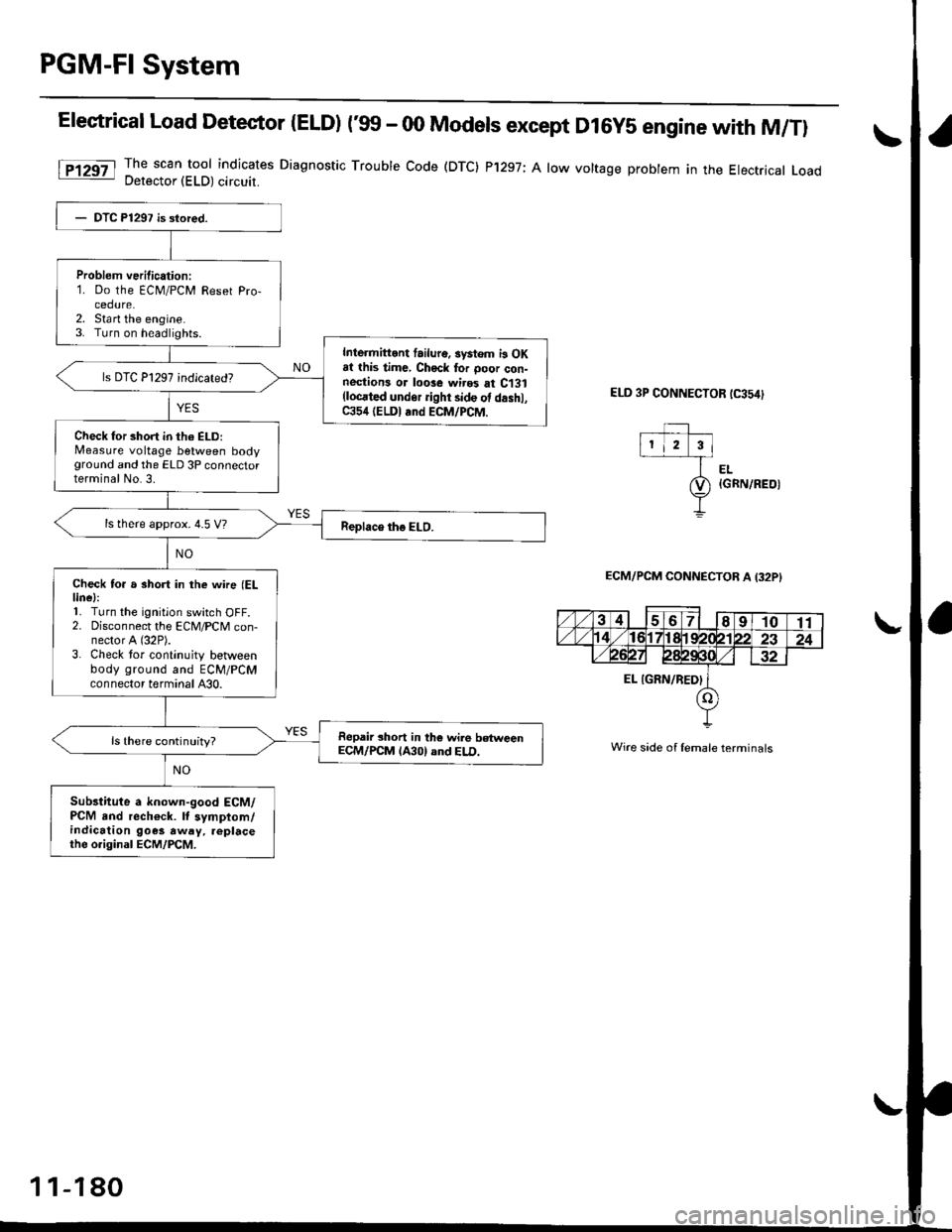
The scan tool indicates Diagnostic Trouble Code (DTC) P'1297; A low voltage probtem in the Electrical LoadDetector (ELD) circuit.
ELD 3P CONNECTOR tC354)
EL{GRN/REOI
ECM/PCM CONNECTOB A I32PI
Wire side of lemale terminals
Problem verilication:1. Do the ECM/PCM Reset Pro-cedure.2. Sta rt the engine.3. Turn on headlights.
Inlermittont failur6. systom i3 OKat this time, Chock tor ooor con-nestions or loose wires at C131(locrted undor ight side ot d.shl,C354 (ELDI and ECM/PCM.
Check for short in th6 ELD:Measure voltage between bodyground and the ELD 3P connectorterminal No.3.
ls there approx. 4.5 V?
Check to. a short in the wne (ELlinel:'L Turn the ignition switch OFF.2. Disconnect the ECM/PCM con-nector A (32P).
3. Check tor continuity betlveenbody ground and ECM/PCMconnector terminal A30.
Repair short in the wile betweenECM/PCM lA30) and ELD.ls there continuity?
Sub3titute a known-good ECM/PCM and rech€ck. It symptom/indication goes away. replacethe o.iginal ECM/PCM.
1 1-180