1997 HONDA CIVIC Dor connector
[x] Cancel search: Dor connectorPage 451 of 2189

PGM-FI System
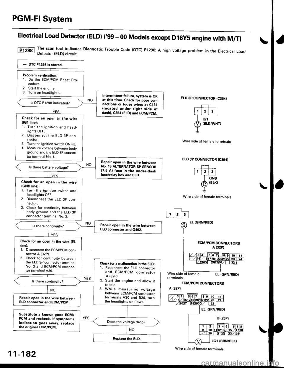
Elestrical Load Detector (ELDI ('99 - 00 Models except D16y5 engine with M/Tl
The scan tool indicates Diagnostic Trouble code (DTCI Pl298: A high vottage problem in the Etectrical LoadDetector (ELD) circuit.
ELD 3P CONNECTOR (65/0
EL {GRN/REOI
Wire side of fernale terminals
ELD 3P CONNECTOR (CA54I
TIr l2l3l
I crvo
(o) (BrKr
Y
Wire side of lemale terminals
ECM/PCM CONNECTORSA (32P1
Wire side of lemaleEI- IGRN/RED)terminals
ECM/PCM CONNECTORS
A {32P)
Problem ve.itication:1. Do the ECN4/PCM Reset pro
cedure.2. Start the engine.3- Turn on headiights.Inte.mittent teilu.e, svstem is OKat this lime. Chock for Door con-nections or loose wires at Ci31{located under Jight side otdaihl, C354 (ELD) and ECM/PCM.
ls DTC P1298 indicated?
Check for an open in the wire{lG1 line}:1. Turn the ignition and head-lights OFF.2. Disconnect the ELD 3P con
3. Turn the ignition switch ON (ll).4. Measure voltage between bodyground and the ELD 3P connec-torterminalNo. 1.
Repair opon in tho wiro batwe€nNo. 15 ALTERNATOR Sp SENSOR{7.5 A} fuse in th6 undor-dashIuse/reley box and ELD.
ls there battery voltage?
Check for an open in the wiro{GND linel:1. Turn the ignition switch andheadlights OFF.2. Disconnect the ELD 3P connector.3. Check for continuity betweenbody ground and the ELD 3Pconnector terminal No. 2,
Repair open in the wire bstwoenELD connsctor and Gia02.
Check ,or an open in the wire IELlinel:1. Disconnect the ECM/PCM con-nector A (32P).2. Check for continuity betweenthe ELD 3P connector terminalNo. 3 and ECM/PCM connec-tor terminal A30.
Chock fo. a malfunction in the ELD:'1. Reconnect the ELD connectorand ECM/PCM connectorA (32P).
2. Stan the engine and allow itto idle.3. While measuring voltagebetween ECM/PCM connectorterminals A30 and B2O, turnthe headlighrs on ow).
ls there continuity?
Repsir op€n in the wire betweenELD connector and ECM/PCM.
Substitute a known-good ECM/PCM and recheck. lf symptom/indication goes away. replacelh6 original ECM/PCM.
Does the vokage drop?
Wire side of f€male terminals
11-182
Page 543 of 2189

Emission Control System
Evaporative Emission (EVAP) Gontrols (cont'd)
'99 - 0O models only:
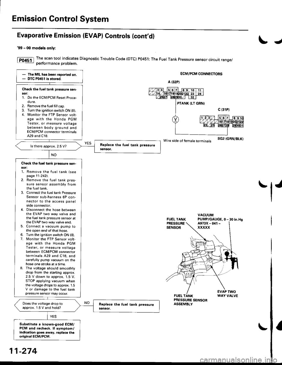
The scan tool indicates Diagnostic Trouble Code (DTC) P0451: The Fuel Tank Pressure sensor circuit range/oerformance Droblem.
ECM/PCM CONNECTORS
wire side ot femare terminars sG2 IGRN/BLK)
FUEL TANKPRESSURESENSOR
VACUUMPUMP/GAUGE,0 - 30 in.Hg
FUEL TANKPRESSURE SENSORASSEMBLY
EVAP TWOWAY VALVE
IJ
tl'
Ths MIL has been reDortgd on.DTC m/$1 i3 stored.
Check the tuel tank pros3ure ser|-sor:1. Do the ECM/PCM Reset Proce-dure.2. Remove the tuellill cap.3. Turn the ignition switch ON (ll).4. N4onitor the FTP Sensor volt-age with the Honda PGMTester, or measure voltagebetween body ground andECN4/PCM connector terminalsA29 and C18.
ls there approx. 2.5 V7
Check tho tuel tank pressure !on-soa:1. Remove the fuel tank (seepage 11 2421.2. Remove the fuel tank pres-sure sensor assembly fromthe fueltank.3. Connect the fuel tank PressureSensor sub-harness 6P con-nector to the access panelside connector,4. Disconnect the hose betweenthe EVAP two way valvg andthe fuel tank pressure sensor atthe EVAP two way valve end.5. Connect a vacuum pump tothe open end ofthat hose.6. Turn the ignition switch ON (ll).7. Monitor the FTP Sensor volt,age with the Honda PGMTester, or measure voltagebetween ECM/PCM connectorterminals A29 and C18, andcarefully pump vacuum on thehose one stroke at a time.8. The voltage sho!ld smoothlydrop from the stading approx.2.5 V down to approx. '1.5 V.STOP applying vacuum whenthe voltage drops to approx. 1.5V or damage to the fuel tankpressure sensor may occur.
Does the voltage drop toapprox. 1.5 V and hold?
Sub3titute a known-good ECM/PCM and r6check. It symptom/indicltion 90e3 aw.y, replac\. th€original ECM/PCM.
A (32P)
A973X - 041 -
xxxxx
11-274
Page 548 of 2189

\
Fue| Tank Pr€ssure sensor 196 Dr6Y8 engine (coupe},,97 D16Y7 angino (coupo: KL mode|' 3edan: KL (Lxl modg||',97
Dl6Y8 engine (coupe: all modeb, sedan: Ki model.'98'all modols) 39 - 0O Dl6Y5 ongins with M/Tl:
rFoG'l::;Jl"too|indicatesDiagnosticTroub|ecode(oTc)P0453;Ahighvo|tageprob|emintheFue|TankPressure
ECM/PCM CONNECTOR D Il6PI
PTANKILT GRNI
\
Wire side of tgmale torminals
FUEL TANKPRESSURE SENSOR3P CONNECTOR (C792)
vcc2(YEL/BLU}
sG2(GRN/BLKI
Wire sid€ of female terminals
I
sG2IGRN/BLKI
PTANKIGBN/RED}
(cont'd)
11-279
The MIL has beon reponed on
DTC P0453 b stored.
Check the vacuum lines:
Check the vacuum lines oI the
fueltank pressure sensor for mis-
routing, leakage, breakage and
clogging.
Are the vacuum lines OK?
Problem verification:1. Do the ECM/PCM Reset Proce-
dure.2. Femove the fuel fill cap
3. Turn the ignition switch oN (ll).
4. Monitor the FTP Sensor volt-
age with the Honda PGM
Tester, or measure voltage
between bodY ground and
ECM/PCM connector termrnal
D15.
lntormittont t iluro, 3Ystem is OK
at this time. Check lot Poor con_
noctiona or loo3e wirat at C131
{loc.ted undor right 3id6 of d8hl,
CaOl llocatod rbov. under-dalh
fus6/relay boxl, C574 (C568lr
llocatod und6l accoss Pan6ll,C792 lfuel tank Preasulo aonlorl
end ECM/PCM.
ls there approx. 2 5 V?
Check for an oPen in the wire(SG2line):1. Turn the ignition switch OFF.
2. Reinstall the fuellill cap
3. Disconnect the fuel tank Pres-sure sensor 3P connector.
4. Turn the ignition switch ON (ll)
5. Measure voltage between the
fuel tank Pressure sensor 3P
connector terminals No. 1 and
No.2.
Ropair opon in the wira b€tw€sn
the fuel tank prasure sonlor and
ECM/PCM (Dl1).ls there aPProx. 5 V?
Check for an open in the wire(PTANK line):Measure voltage between the
fueltank Pressure sensor 3P con-
nector No. 3 terminal and No. 2
termrnal,
ls there approx. 5 V?
*: coupe
{To page 11-280)
Page 585 of 2189

Transmission Assembly
I
Removal
@. Make sure iacks and safety stands are placed prop€dy,
and hoist brackets are atlach€d to correct position on
the enginc.
. Apply parking brake and block rear whosls so car will
nol roll olf stands and lall on you while working under
it.
CAUTION: Use fender covers to svoid damaging painted
surfaces.
1. Disconnect the negative {-) cable first, then the pos-
itive (+) cable from the battery'
Drain transmission oil {see page 13-3).
Remove the intake air tube. intake air duct and air
cleaner housing assembly (see section 5).
Disconnect the starter motor cables, transmission
ground wire and back-up light switch connector.
6x1.0 mm BACK-UP LIGHT
9.8 N.m (1.0 ksf.m, 7.2 lbI.ft) swlTcH CoNNECTOR
8x 1 .25 mm8.8 N.m {0.9 kgt.m,6.5 lbf.ftl
\
ARTER
5. Remove the wire harness clamps.
vssCONNECTOR
6. Disconnect the vehicle speed sensor (VSS) connec-
ror.
Remove the clutch line bracket, clutch line clamp,
and slave cvlinder.
CAUTION:
. Do not opsr.te tho clutdh pedal once the 3lavc
cylindor has b6on romoved.
. Tske care not to bend tha clutch lin6.
7.
(cont'd)
13-5
Page 758 of 2189

Electrical Troubleshooting ('99 - 00 Models)
Troubleshooting Flowchart - Lock-up Control Solenoid Valve A
NOTE: Record all freeze data before vou troubleshoot.
Possible Cause
. Disconnocted lock-uD controlsolenoid valve A/B alsemblyconnector. Short or opon in lock-up conkolsolenoid valv6 A wire. Faulty lock-up control solenoidvalva A' Open in VB SOL wireFCM CONNECTORS
LGl IBRN/BLXI LG2 (BRN/BLK)
Wire side ot female terminals
LGl (BRN/BLKILG2 IBRN/8LK)
To page 1+81
a\
. OBD ll Scan Tool indic.t6 CodeP1753.. Self-diagnosis @ indicatorlight blink3 once.
Check lor a Short to Power:L Turn the ignition switch OFF.2. Disconnect the B (25P) and D(16P) connectors lrom thePCt\4.3. Turn the ignition switch ON (ll).4. Measure the voltage betweenthe Dl and 820 or 822 termi-nats.
Ropair short to powcr in the wirebstwoon tho Dl tolminal and thelock-up cor|lrol lolonoid valvo A.
Measu.e Lock-up Cont.ol Sole-noid V.lvo A R63btanc6:1. Turn the ignition switch OFF.2. Measure the resistancebetween the Dl and 820 or822 terminals.
ls the resistance 12 - 25 O?
Measure VB SOL Vohage:1. Turn the ignition switch ON (ll).2. Measure the voltage betweenthe D5 and 820 or 822 termi-nals.
Check for blown No. 15 17.5 Alfu3€ in the undordash fuse/rabybox. l{ th€ tusa ii OK, r.pair oponin the wira b€twoen th€ 05 torfti-nal and thc und€r{ash fuso/r€laybox.
Check to.loose tarminalfit in thePCM connecloa3. ll necessary,substilute a known-good PCMand rocheck.
B (25Pt ll D {16P1
B (2sPt ll D {16P1
I t25Pt D (16P1
l..
14-80
Page 765 of 2189

Troubleshooting Flowchart - A/T Gear Position Switch (Open)
NOTE: Record allfreeze data before you troubleshoot.
Po$ible Cause
. Disconnectod A/T goar position
switch conngdor. Open in A/T gear position
switch wire. Fautty Aft gear poshion switch
PCM CONNECTORS
Wire side of lemaleterminals
D (16P1
GRNI
B (25Pt llDtl6Pl
IARN/BLK) LG2IBRN/BLKI
2{6,|235
I't011/t5l/18912
ATP NP (LT
. OBO ll Scan Tool indicatd CodcP1706.' Sslf-diagnosis E indicatorlight blink3 six tim6.
Test the Ay'T gear position switch(see section 23).
Moasure ATP R Volt.ge:'1. Turn the ignition switch ON ('l).
2. Shift to E position.
3. Measure the voltage between
the D6 and 820 ot 822 termi'nals.
Repoir opon in the wire bitween
the D6 torminll and the A/T go.r
position switch.
Measuro ATP NP Volt ge:
1. Shift to E or E position.
2. Measlre the voltage betweenthe D13 and 820 or 822 termi-nals,
Ropair op€n in thc wire betwoonthe D13 terminrl and the A/Tge.r position switch.
LG1 {BBN/BLKI
Io page 14-88
(cont'd)
Page 920 of 2189

Troubleshooting Flowchart - Vehicle Speed Sensor (VSS)
NOTE: Record all freeze data before you troubleshoot'
Po$rible Ctuse
. Disconnected vehicle speed
sensor (VSS) connectol. Short or open in VSS wire' Faulty VSS
@. Make sure lifts, iacks, and sal€tY stands are placed properly lsoe section 1)'
. Set the parking brake securelv, and block the rear wheels'
. iacr upile rront or the vehicle, and support it with safety st'nds'
TCM CONNECTORS
Wire side of female terminals
. OBD ll Scan Tool indicates Code
P1791.. Setf-diagno3is E indicato. light
blinks tour times.
Refer to seclion 23 for vehicle
soeed sensor IVSSI test
Check the VSS Voltage:
1. Raise the vehicle2. Shift the transmission to lEposrtlon.3. Disconnect the A (26P) and B(22P) connectors from the
TCM.4. Turn the ignition switch ON {ll).
5. Rotate the front wheel and
check for the voltage between
the 85 and 413 or A26 termi-
nals. Block the other wheel so
at does not turn
Check for oP€n in the wire
between the 85 terminal and the
vehicle speed sensor {VSS}. lf
wire is OK, check the vSS (see
soction 23).
Does0Vandapprox 5 V or more
appear alternatelY?
Check for loos€ TCM connedors
lI nec€ssary, substitute a known'
good TCM and recheck.
14-243
Page 930 of 2189

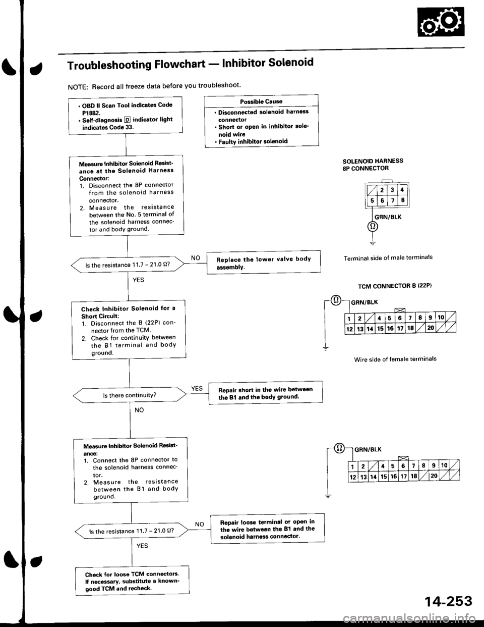
Troubleshooting Flowchart - Inhibitor Solenoid
NOTE: Record all treeze data betore you troubleshoot
Po$ibls Cause
. Dbconnected solenoid hatness
connedor' Short or opon in inhibitor sole'
noid wire. Faultv inhibitor solenoid
SOLENOID HARNESS8P CONNECTOR
Terminal side of male terminals
. OBD ll Scan Tool indic.td Code
P1882.. Selt-di.gnGis E indicator lighl
indic.tos Code 33.
Mea3ure Inhibhor Solenoid Resid-
ance at the sol€noid Harness
Connector:1. Disconnect the 8P connector
from the solenoid harness
connector.2. Measure the reslstance
betlveen the No 5 terminal of
the solenoid harness connec-
tor and body ground.
ls the resistance 11.7 - 21 0 0?
Check Inhibitor Solenoid lor a
Short Circuii:1. Disconnect the B (22P) con-
nector from the TCM.
2. Check for continuity between
the B1 terminal and bodygro!no.
Repair rhort in the wire ltetwegn
the 81 dnd the bodY ground.
Mea$rr€ Inhibitor Solenoid ResBt'
anoe:1. Connect the 8P connector to
the solenoid harness connec_
IOr.2. Measure the resistance
between the Bl and bodyground.
Reoair loose terminal or open in
the wire betwean the 81 and the
solenoid hame3s connector'ls the resistance 11.7 - 21.0 O?
Ch6ck for loose TCM connectors.
ll necessary, substhule a known_good TCM and techeck.
Wire side of female terminals
14-253