1997 HONDA CIVIC Sensors
[x] Cancel search: SensorsPage 356 of 2189
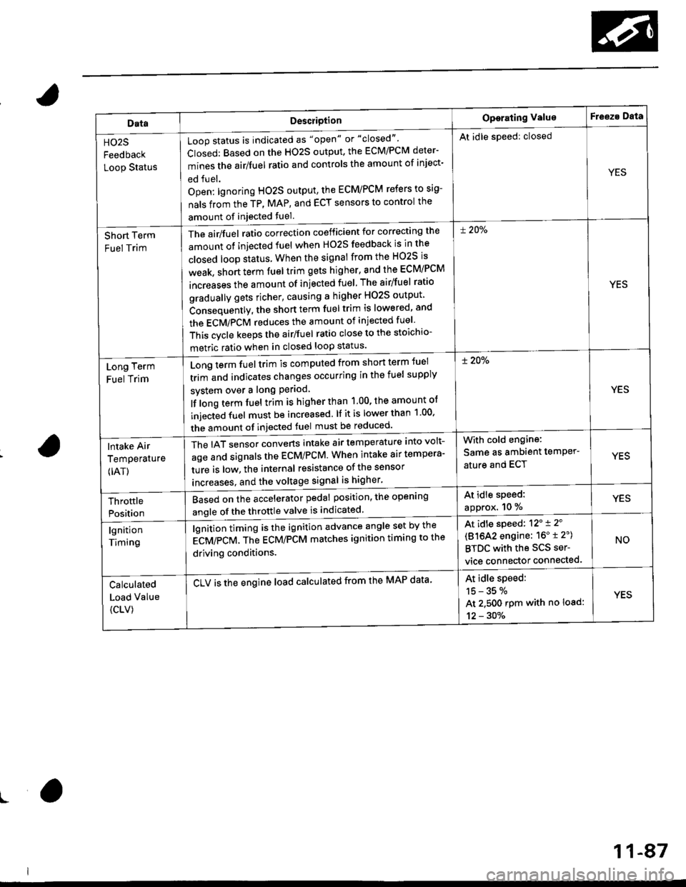
DataDescriotion
Loop status is indicated as "open" or "closed"'
Closed: Based on the HO2S output, the ECM/PCM deter-
mines the airlfuel ratio and controls the amount of inject-
ed fuel.
Open: lgnoring HO2S output, the ECM/PCM refers to sig-
nals from the TP, MAP, and ECT sensors to control the
amount of injected fuel.
The air/fuel ratio correction coefficient for correcting the
amount ot injected fuel when H02S feedback is in the
closed loop status When the signal from the HO2S is
weak, short term fuel trim gets higher, and the ECM/PCM
increases the amount of injected fuel The airlfuel ratio
gradually gets richer, causing a higher HO2S output
Consequently, the short term fuel trim is lowered, and
the ECMiPCM reduces the amount of injected fuel
This cvcle keeps the airlfuel ratio close to the stoichio-
metric ratio when in closed loop status'
Operating ValueF eeza Data
HO2S
Feedback
Loop Status
At idle speed: closed
YES
Short Term
Fuel Trim
! 20%
YES
Long Term
Fuel Trim
Long term fuel trim is computed from shon term fuel
trim and indicates changes occurring in the fuel supply
svstem over a long Period
lf long term fuel trim is higher than 1.00, the amount of
injecGd fuel must be increased. lf it is lower than 1 00'
the amount of injected fuel must be reduced'
! 20%
YES
lntake Air
Temperature
{IAT)
The IAT sensor converts intake air temperature into volt-
age and signals the ECM/PCM. When intake air tempera-
ture is low, the internal resistance of the sensor
increases. and the voltaqe signal is higher'
With cold engine:
Same as ambient temPer'
ature and ECTYES
At idle speed:
approx. 10 %YESThrottle
Position
Based on the accelerator pedal position, the open'ng
angle of the throttle valve is indicated
lgnition
Timing
lgnition timing is the ignition advance angle set by the
gCV/eCV. tn" gCU/PCM matches ignition timing to the
driving conditions.
CLV is the engine load calculated from the MAP data'
At idle speed: 12'i 2'
(81642 engine: 16" t 2")
BTDC with the SCS ser-
vice connector connected.
NO
Calculated
Load Value
{CLV)
At idle speed:
15-35%
At 2.500 rpm with no load:
12 - 30%
YES
ro
11-87
Page 363 of 2189
Troubleshooting
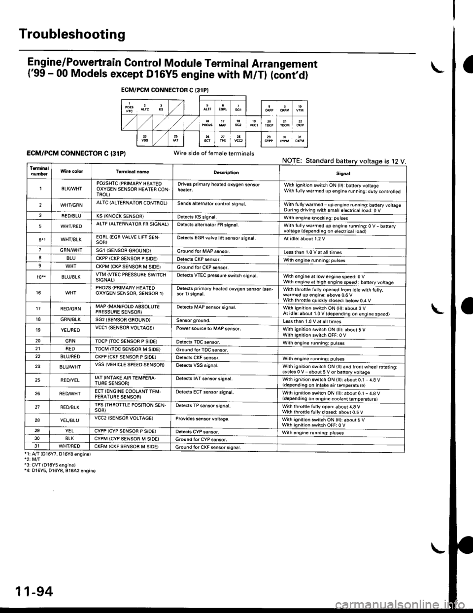
Eng ine/P_owertrain Control Module Term inal Arrangement
('99 - 00 Models except Dl6Y5 engine with M/Tl (cont,d)
ECM/PCM CONNECTOR C {31P)Wire side of female terminalsNOTE;Standard
*1;4"/T lD16Y7, D16Y8 ensinel
43: CVI(016Y5 engine)'4: D16Y5, D16Y8, 81642 engin€
ECM/FCM CONNECTOR C 13lPI
is 12 V.
Sig.al
lBLK4/VHTPO2SHTC (PNIMARY HEATEOOXYGEN SENSOB HEATES CONTROL)
Drivss primary hoated orygen sensofWith ignition switch ON (lr)rbanery volageWrh fJly warned up €ngir. ru..i19: duty.oaro ed
2WHT/GFNALTC (ALTESNATOB CONTSOL)Sends aliernalo. control sig nal,With fullywa.med upengine ronning; banery vohaseDuring d.iving with smallelect.icatioad; O V38ED/BLUK5 (KNOCK SENSOR)with sngine knocking: pulses
5WHT/REDATTF {AITEFNATOR FR SIGNAL'Detects slternaror FR si9n.l.With tullywarmed up engine running:O V- batteryvortage(dependingon erectficat toad)
WHT/8LKEGRL (EGN VAIVE LIFTSENSOR)Dete.ts EGR valve lrft sensorsignat.
GRN,4r'l/flTSGl ISENSOE GBOUND)Groond fo. MAP s€nsor.L€ss rhan 1.0 v at alltimes88luCKPP (CKP SENSOR P SIOE'With engine running: pulses9CKPM {CKP SENSOR M SIDEIGround for CKP sensor.
BLU/BLKwlvl (wEc PREssuSE swtTcllSIGNAI)D€tocts VTEC pfessure switch signat,With €ngine at low enginospeed:0VWith engin€ at high engino speed : banery vo ttaae
16PHO25 (PRII\,1AFY HEATEDOXYGEN SENSOR, SENSOR 1)Oetects primary heated oxygen s6nsor lsen-With lhrottle f!l1y open€d from idtewith tuly,wa.med !p engin€: Ebove 0.6 VWilh thronl€ quickly closed: b€tow 0.4 V
FED/GRNMAP (I\,4ANIFOLD ASSOLUIEPFESSUSE SENSOB}Dotocrs i,4AP sensor signsl.With ignitioh switch ON (ll):about 3 VAt idlei6boul 1.0 V (depending on engine speed)18GBN/8LKSG2 (SENSOR GSOUND)Less than 1.0 V aralttimes'19YEUNEDVCCl (SENSOR VOLTAGEIPowersourcero MAPsenso..With ignition swilch ON {ll):about 5 VWirh iqnition switch OFF]0 V20GNNIDCP (TDC SENSOB P SIDEIWith ongine running: pulses218EDTDCI\,I (TDC SENSOR M SIOE)Ground lor TOC aensor.22BTU/NEDCKFP (CKF SENSOR P SIDE)With engine running: p!lses
23VSS {VEHIClE SPEED SENSOR)Wilh ignrt|on swich ON rllr snd lront wl-ee' rotating.cycles 0 V about 5V or baneryvottage
25BED/YELIAT ONTAKE AIF TEi,4PEBA.TUEE SENSOR)Detects IAT senso. signat.With ignition switch ON (ll): about 0.1 4.8 Vldepending on i.take air ternpe.atu re)
268ED,ryVHTECT (ENGINE COOLANTTEI\,I.PESATUBE SENSOR)Oelects ECT sensor signal.With ignirion swirch ON {ll):about0.1 -4.8 V(depending on engine coolant temperatu re)
21NED/BLKTPS (THROTTLE POSITION SEN,SOF)Detects TP sensor signal.Wilh th.onle fully op€n: about 4.a VWith rhronle f!lly closed: about 0.5 V
2aYEVBLUVCC2 (SENSOR VOLTAGE)Provides s6nsor voltag€.With ignirion swirch ON (tt):about 5VWith ignilion swiich OFF:0 V29YELCYPP (CYP SENSOR P SIDE)Wilh €ngrne running: pruses3oBLKCYPM (CYP SENSOR M SIDE]G,ound for CYP sonsor.J1WHT/FEDCKFM (CKF SENSOB M SIDE)Ground fo. CKF sonsorsign6i.
11-94
Page 367 of 2189
Troubleshooting
DTClMlL indicationlDatection hsmProbablo CausePage
P0137(63)Secondary Heated Oxygen SensorCircuit Low Voltage(Sensor 2)
Short in Secondary HO2S lSensor 2) circuitSecondary H02S {Sensor 2)ECM/PCI\41 1-153
P0r38 {63)Secondary Heated Oxygen SensorCircuit High Voltage(Sensor 2)
Open in Secondary HO2S (Sensor 2) circuitSecondary HO2S (Sensor 2)EC[I/PCM11-154
P0'139 (63)Secondary Heated Orygen SensorSlow Response(Sensor 2)
Secondary H02S lSensor 2)1l-156
P0141 (65)
Secondary Heated Oxygen SensorHeaterCircuit Malfunction(Sensor 2)
. Open or short in Secondary HO2S (Sensor2) heater circuit. ECM/PCM11-157
P0171 (45)
System Too LeanFuel supply systemPrimary HO2S (Sensor 1)MAP sensorContaminated fuelValve clearanceExhaust leakage
11,164
P0172 (45)
System Too RichFuel supply systemPrimary HO2S (sensor l)MAP sensorContaminated fuelValve clearance
11-164
P0300*16' }l?
andsome ofPo3o1 /r'' \P0302 l72lP0303 l73lP0304 \7 4l
Random Misfirelgnition systemFuel supply systemMAP sensorEGR systemIAC valveContaminated fuelLack of fuel
r1-r66
P0301P0302P0303P0304
/rt\172ll73l\7 4l
- Cylinder 1- Cylinder 2- Cylinder 3- Cylinder 4Misfire Detected
Fuel InjectorFuel Injector circuitlgnition systemLow compressionValve clearance
11 167
P0325*3 (23)Knock Sensor (KS) CircuitMalfunctionOpen or short in Knock Sensor (KS) circuitKnock Sensor {KS)ECM/FCtvl11-170
P0335(4)Crankshaft PositionSensor CircuitMalfunction
Crankshaft Position SensorCrankshaft Position Sensor circuitECM/PCM11-172
P0336(4)Crankshaft PositionSensorRange/Performance
. Crankshaft Position Sensor. Timing belt skipped teeth11-172
P040'�r*r (80)Exhaust GasRecirculationInsufficient Flow Detected
' EGR valve. EGR line
P0420(67)Catalyst SystemEfficiency BelowThreshold
. Th.ee Way Catalytic converter. Secondary HO2S11 253
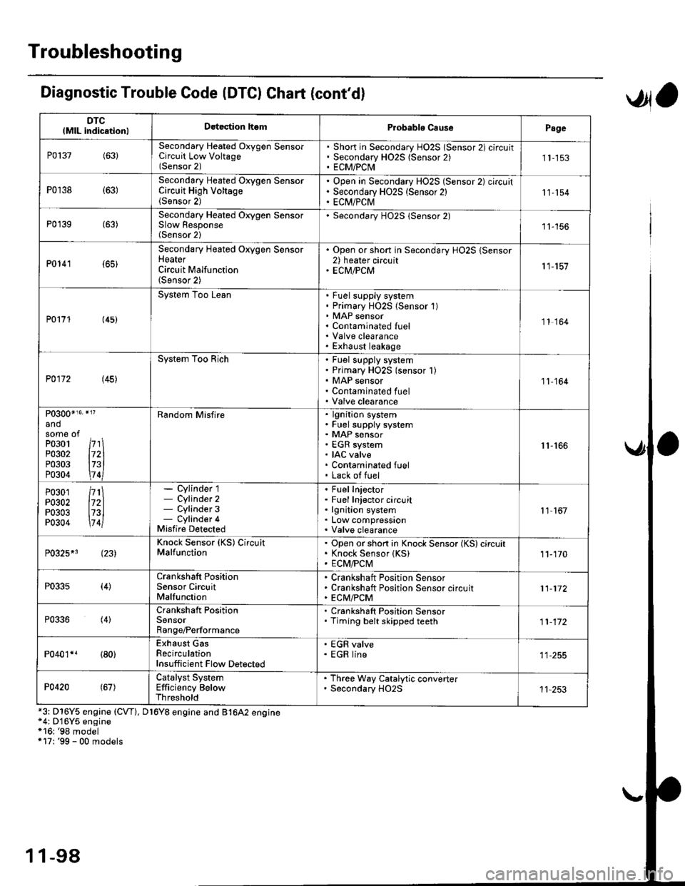
Diagnostic Trouble Code (DTCI Chat (cont'dl
*3: D16Y5 engine (CVT), D16Y8 engine and B1642 engine*4: D'16Y5 engine*16: '98 model+17: '99 - 00 models
,Jla
1 1-98
Page 410 of 2189
Primary Heated Oxygen Sensor (Primary- Fjq?S) (Sensor 1l
('99 - 0b Models exiept D16Y5 engine with M/T)
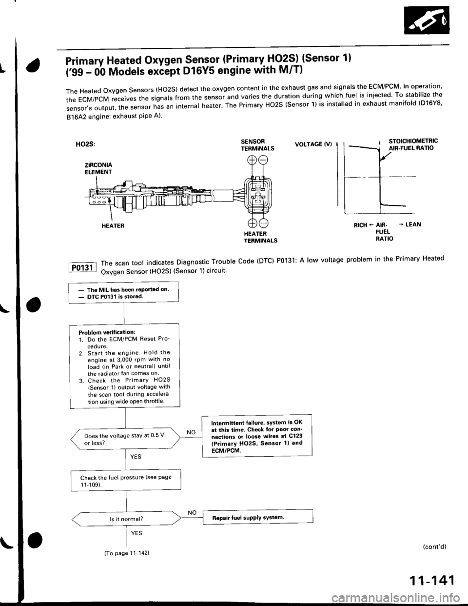
TheHeatedoxygensensors(Ho2S)detecttheoxygencontentintheexhaustgasandsigna|stheEcM/PcM'|noperation,
the EcM/pcM receives the signars from the sensor and varies the duration during which fuel is injected. To stabilize the
sensor,soutput,thesensornasaninternaIheater.ThePrimaryHo2S(sensorl)isinsta|ledinexhaustmanifo|d(D16Y8.
81642 engine: exhaust PiPe A)
SENSORTERMINALSVOLTAG€ (VI
HEATERTERMINALS
The scan tool indicates Diagnostic Trouble Code (DTC) P0131: A low voltage
Oxygen Sensor (HO2S) (Sensor 1) circuit
RICH+ AIR- - LEANFUELRATIO
problem in the Primary Heated
HEATER
- The MIL has been t€Ported on.- DTC P013'l is stored.
Problem veritication:1. Do the ECM/PCM Reset Pro-
2. Start the engine. Hold the
engine at 3,000 rpm wrth no
load (in Park or neutral) until
the radiator fan comes on
3. Check the PrimarY HO2S
lSensor 1) output voltage wath
the scan tool during accelera
tion using wide open throttle
lntermittont f.ilure, 3ystem i3 OK
at thi3 time. Check tor Poor con'
nections or loose wires el C123
{Primary HO2S, Sensor 1) and
ECM/PCM.
Does the voltage stay at 0 5 v
or less?
Check the fuel pressLlre (see Page11,109).
(To page 11 142)(cont'd)
11-141
Page 441 of 2189

PGM-FI System
tFos3sl
tFffi6l
tPr361 I
fPfi62l
fFr38il
tF13s2-l
Crankshaft Position/Top Dead Genter/Gylinder Position (CKP/TDC/CYP) Sensor
('96 - 98 Models, '!n - 00 D16Y5 engine with M/Tl
The scan tool indicates Diagnostic Trouble Code (DTC) P0335: A malfunction in the Crankshaft position (CKp)
sensor circuit.
The scan tool indicates Diagnostic Trouble Code (DTC) P0336: A range/performance problem in the CrankshaftPosition (CKP) sensor circuit.
The scan tool indicates Diagnostic Trouble Code (DTC) P1361: Intermittent interruotion in the Too Dead Center(TDC) sensor circuit.
The scan tool indicates Diagnostic Trouble Code {DTC) P1362: No signal in the Top Dead Center (TDC} sensorcircuit.
The scan tool indicates Diagnostic Trouble Code (DTC) P1381: Intermittent interruption in the Cvlinder Position{CYP) sensor circuit.
The scan tool indicates Diagnostic Trouble Code {DTC) Pl382: No signal in the Cylinder Position (CYP} sensorcircuit.
Description
The CKP Sensor determines timing for fuel injection and ignition of each cylinder and also detects engine speed. The TDCSensor determines ignition timing at start-up (cranking) and when crank angle is abnormal. The Cyp Sensor detects theposition of No. 1 cylinder for sequential fuel injection to each cylinder. The CKP/TDC/CYP Sensor is built into the distribu-ror.
NOTE: lf DTC P1359 is stored atthesametime as DTC P0335. P0336, P1361, Pl362, P1381 and/or P1382, troubteshoor DTCP1359 first, then recheck for those DTCS. Ot6y5 6ngine: Dt6y7, ot6y8 enqin6s:
SENSORBOTOR
TDCSENSORCKPSENSORSENSORROTORSENSORROTORSENSORROTORROTORROTOR
DISTRIBUTOR 1OPcoNNECTOR tC120tTDC P
- The MIL hrs been reported on.- DTC P0335, P0336, P1361,P1362, P1381 and/or Pl382 6restored,
Problem verification:1. Do the ECM/PCM Reset Proce-dure.2. Stan the engine.
Intermittent hilu.e, system b OKat this time. Check tor poor con-n€ctions or 10036 wiros at C120{distributor} and ECM/PCM.
ls DTC P0335, P0336, P1361, P1362,P1381 and/or P'l382 indicated?
Check for an open in the CKP/TDC/CYP sensor:1. Turn the ignition switch OFF.2. Disconnect the distributor 10P
3. Measure resistance betweenthe terminals of the indicatedsensor (*see table).
Replace the distributor ignitionhousing (soe section 23).ls there 350 - 700 0?
CYP M {BLK}
SENSORDTCSENSORIERMINATECMfCMTERMINATCOLOR
CKPP033s
m336
2c2BLU
6c12
TDCP1361
P1362
3GRN
7cl3RED
CYPP!381
P't382
c4YEL
8c148LK11-172
Page 459 of 2189

ldle Control System
System Description
The idle speed ot the engine is controlled by the ldle Air Control (lAC) Valve.The valve changes the amount of air bypassing into the intake manifold in response to electric current controlled bv theECM/PCM. When the IAC Valve is activated, the valve opens lo maintain the proper idle speed.
D16Y5, D16Y8, Br6A2 engine (M/T):
(ROTARYItac vat-vEEI{GINEcooLAI{T
VARIOUSsEI{SORS
VARIOUSSENSORS
INTAKE MANIFOTDDl6Ys {CVTl, D16Y8 engine lA/T):
D16Y7 engine:
{ROTABY)
;iy--, - ---
11-190
Page 512 of 2189

Intake Air System
\JSystem DescriPtion
The system supp|ies air for a|| engine needs' |t consists of the intake air pipe' Air C|eaner (ACL}, intake air duct, Thrott|e
Body (TB), ldle Air control (lAc) valve and intake manifold. A resonator in the intake air pipe provides additional silencing
as air is drawn into the system.
D16Y5, D16Y8, 816A2 engine {M/Tl
YEL/ - From PGM-FIaLK - MA|N RELAY
BLK/BLU
-- ORN
INTAKEAIRDUCT
IROTARYIIAC VALVE
Iaru
ENGINECOOLANT
BLK/
INTAKEAIR DUCT
I
D16Y5 engine (CVT), D16Y8 engine (A/T)' f'ttlxr ,tla"tpoto
D16Y7 engine:
{ROTARY)IAC VALVE
VARIOUSSENSORS
INTAKEAIRPIPE
tr
RESONATOR
!r,
IAC VALVE
BLK
11-243
Page 523 of 2189
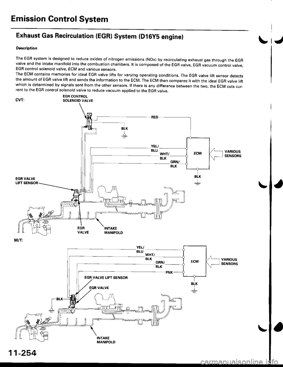
Emission Control System
Exhaust Gas Recirculation (EGR) System (D16yS engine)
Doscription
The EGR system is designed to reduce oxides of nitrogen emissions (NOx) by recirculating exhaust gas through the EGRvalve and the intake manifold into the combustion chambers. lt is composed of the EGR valve. EGR vacuum conrrot vatve.EGR control solenoid valve. ECM and various sensors.The EcM contains memories for ideal EGR valve lifts for varying operating conditions, The EGR valve lift sensor detectsthe amount of EGR valve lift and sends the information to the ECM. The ECM then compares it with the ideat EGR valve liftwhich is determined by signals sent from the other sensors. lf there is any difference between the two. the EcM cuts cur-rent to the EGR control solenoid valve to reduce vacuum applied to the EGR valve.
EGR CONTROLCVT: SOLENoID vALvE
EGN VALVE LIFT SENSOR
BLK
I
I
11-254