1997 HONDA CIVIC Sensors
[x] Cancel search: SensorsPage 1858 of 2189
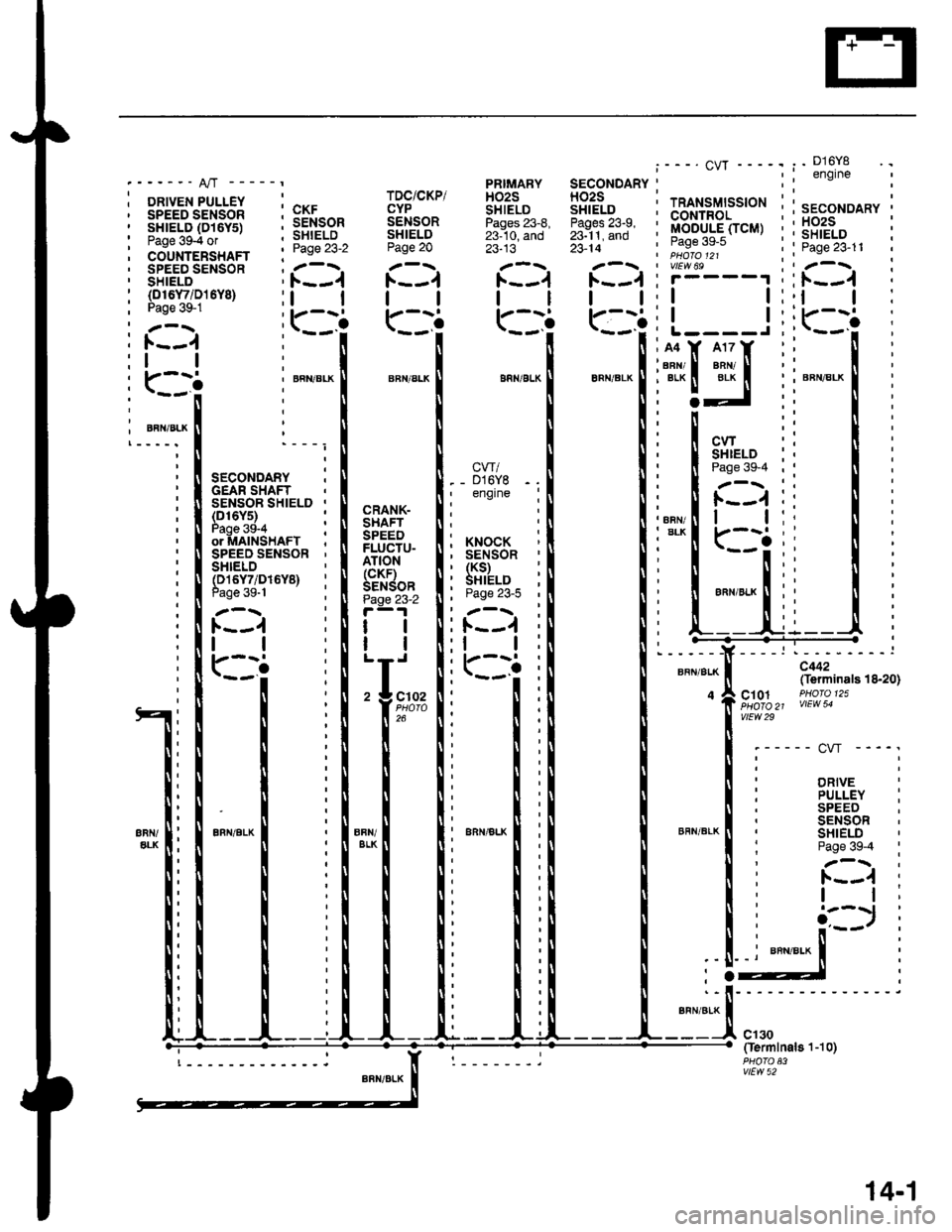
----" A/T -----t
DRIVEN PULLEY , ^.,.
;iftTBilis'".f l5Ftr,.""_
co'rinienixnn '. Pase 23'2
SPEED SENSOR ; .'-\.SHIELD 'F--.1
TDC/CKP/CYPSENSORSHIELDPage 20
ll
r_:.-i
23-13
t1
23- l4
tl
PRIMARY SECONDARYHO2S HO2SSHIELD SHIELDPages 23-8, Pages 23-9,23-10. and 23-11. and
--- CW ----.
TRANSMISSION ;CONTROLMODULE(TCM) ,Page 39-5 :PHO|O 121vlEw 69r____1 ,
tt:
tt:L----J,
. D16Y8engine
SECONDARY .
HO2S :SHIELD ;Page 23-11
l. - -..1 ;
tt:(D16Y/i D15Y8)Page 39-1
l.--.1
1l
r:--iBFN/BLKARN/BLK
A4
6FN/BLK' EFN/BI
i i srco"oo"t :' I GEAR SHAFT
I I Or MAtN!'tAt I. II SPEED SENSOR '
CW. - D16Y8 -, engine: N SENSoR SHTELD ,
i !i?il3li*u,, i
CWSHIELD :Page39-4,
CRANK-SHAFTSPEEDFLUCTU-ATION(cKF)SENSORPage 23-2
tl
ll
;I;..
26
i xNocx' SENSOR, (KS)' SHIELD
, Fage zJ-5
: F--.1
:ll
iilr-:i
----:.--------:
c442(Terminals 18-20)
c10.1 PHofo 125\HOTO 21 VIEW 54vtEw 29
'----- cw ----'
DRIVE
BFN/BLK
PULLEY :SPEEDSENSORSHIELDPage 39-4 :
1.---{ :I t;
cl30Oermlnal8'l-10)
vtEw 52
14-'�,
Page 1860 of 2189
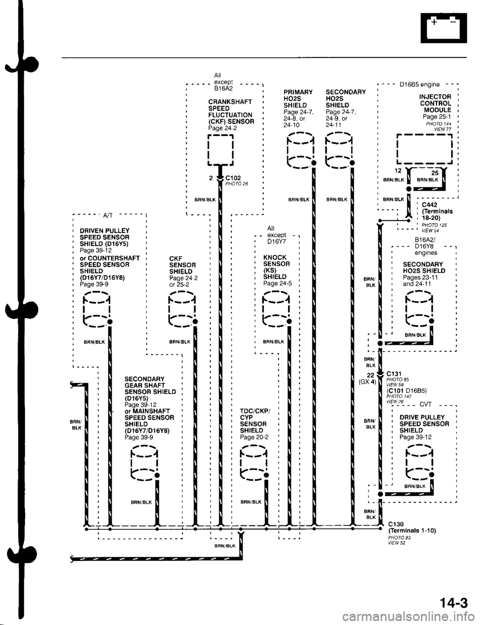
PRIMARYH02SSHIELDPage 24-7 ,24-8, ol24 10
tl
r_i
.--- D1685engine --.
' TNJECTOR I: CoNTROL ;; MoDULE ,, Page 25-1 ,t PHO\O 1aa :I vtEw 77
i r-- --r I,ll:
ill;
816l€I.--- D16Y8I englnes i. SECONDARYI Ho2s SHTELD :, Pages 23-11 I' and 24-11
I z-r; l.--.1 :
c131
(c101 D16Bs)
. ORIVE PULLEY
: SPEED sENsoR I. SHIELD ,' Page 39-12
l---:
: 1.--,1 ;
:l | :
c102
CKFSENSORSHIELDPage 24 2
tl
\..
BFN/BLK
------_I
SECONDARYGEAR SHAFT :SENSOR SHIELD ;(D16Y5)P.^a 'lO,1 ,oifu-alisirrrSPEED SENSOR :SHIELD :(016Y7/D16Y8)Page 39-9
F--.1
tl
rJii
t
rDc/cKP/CYPSENSORSHIELDPage 2O-2
tl
\,.
T
""","a* |
i
___r_
14-3
Page 1945 of 2189
- How the Circuit Works
The anti-lock brake system (ABS) prevents locking
of the wheels as a result of heavy braking and/or
poor lraction. A vehicle with locked wheels cannot
be steered. The anti-lock brake system controls the
application of the brakes, allowing the driver to
maintain control of the steering.
Under anti-lock conditions, the antilock brake
system (ABS) modulates the pressure of the brake
tluid to each brake caliper. This system is a four
channel system: the pressure at each caliper is
controlled independently of the pressure al any
other caliper. Whenever a wheel is likely to lock
dunng braking, the anti-lock brake system
modulates the brake oressure at that wheel. When
the brake pressure is reduced to the point where
there is no longer any possibility of wheel locking,
the system returns to the conventional braking
system mode of operation.
Battery voltage is applied at all times through fuse
63 to the ABS control unit. When the ignition switch
is in ON (ll), battery voltage is supplied to the
control unit through fuse 16. The control unit is case
grounded. Inputs are received from the brake switch
and the individual wheel sensors located at each
wheel. The ABS control unit uses these inputs to
control the modulator solenoid unit. The solenoids
adjust the hydraulic pressure applied to each
calioer.
The ABS control unit has a self-diagnosis function.
When the control unit detects a fault, it turns on the"ABS" indicator and disables the anti-lock brake
system. lf the fault is not in the conventional braking
system, the brakes will continue to operate normally
but without the anti-lock feature.
Refer to the Service Manual (Section '19,
Anti-Lock Brake System) for specific tests or
troubleshooting procedures.
44-3
Page 2055 of 2189
How the Circuit Works
Arming the Security System
The security system can be armed:
r By pressing the remote control LOCK button
(if equipped)
. 20 seconds atter closing all doors (C)UDX only)
Arming with the Transmitter
The security system can be armed by removing the
ignition key from the ignition switch, closing all
doors and the trunk, and pressing the LOCK button
on the transmitter. When you arm the system in this
way, the remote control LED comes on, the status
LED flashes once per second, the parking lights
flash once. the doors lock. and the horn sounds
once if the beeo sound mode is on.
Passive Arming (CX and Dx only)
When you turn the ignition to OFF, remove the
ignition key from the ignition switch, and close all
the doors and the trunk; the system will
automatically arm itself 20 seconds after the trunk
or last door is closed. When you arm the system
this way, the status LED tlashes 4 times per second
during the exit delay time, and once per second
after the system is armed; the parking lights will
flash once to confirm that the system is armed.
Triggering the Alarm
Atter you've armed the system, it will trigger the
alarm if any door or the trunldhatch is opened. lf the
battery is disconnected when the system is armed or
in the alarm mode, reconnecting it will immediately
trigger the alarm. When the alarm is triggered, the
following will occur for 30 seconds:
. the horn sounds
o the parking lights flash once per second
. the status LED flashes hvice oer second
. the starter is disabled
After 30 seconds, the alarm will stop and the
system will rearm. Pressing the transmitter
UNLOCK button will disarm the svstem.
tlr
133-13
Disarming the System without the Remote
Transmitter (HX, LX, and EX)
You can disarm the system by turning the ignition
switch to ON (ll) and pressing the disarm/valet
switch on the right side ol the stereo tuner face. The
disarm switch will also disarm the svstem after the
system has been triggered.
Disarming the System with the Remote
Transmitter (Hx, Lx, Ex, DX-V, and Si)
Pressing the transmitter UNLOCK button will disarm
the system. The parking lights llash t\ivice if the
alarm has not been tnggered. The parking lights
flash three times if the alarm has been triggered.
The driver's door will unlock. lf you press the unlock
button twice, it will unlock all doors. lf a door is not
opened within 30 seconds, the system will lock all
doors and rearm.
Disarming the System (CX and DX only)
lf the system arms itself, there is a 20 second delay
after you open a door before the alarm will trigger.
To disarm the system in this mode, simply turn the
ignition switch to the ON position
ldentitying Tripped Sensors
The system identifies which sensor trips the alarm
by flashing the status LED. To display the trip
sensor flash code, press the disarm/valet switch 3
times within 5 seconds after the system has been
disarmed. The status sensor will blink according to
the followino codes:
SensorsNumber of Flashes
Door
TrunldHatch
System Switches
1 blink, pause, repeat
2 blinks, pause, repeat
3 blinks, pause, repeat
For further operating instructions, see the security
syslem owner's manual.
(cont'd)
Page 2163 of 2189
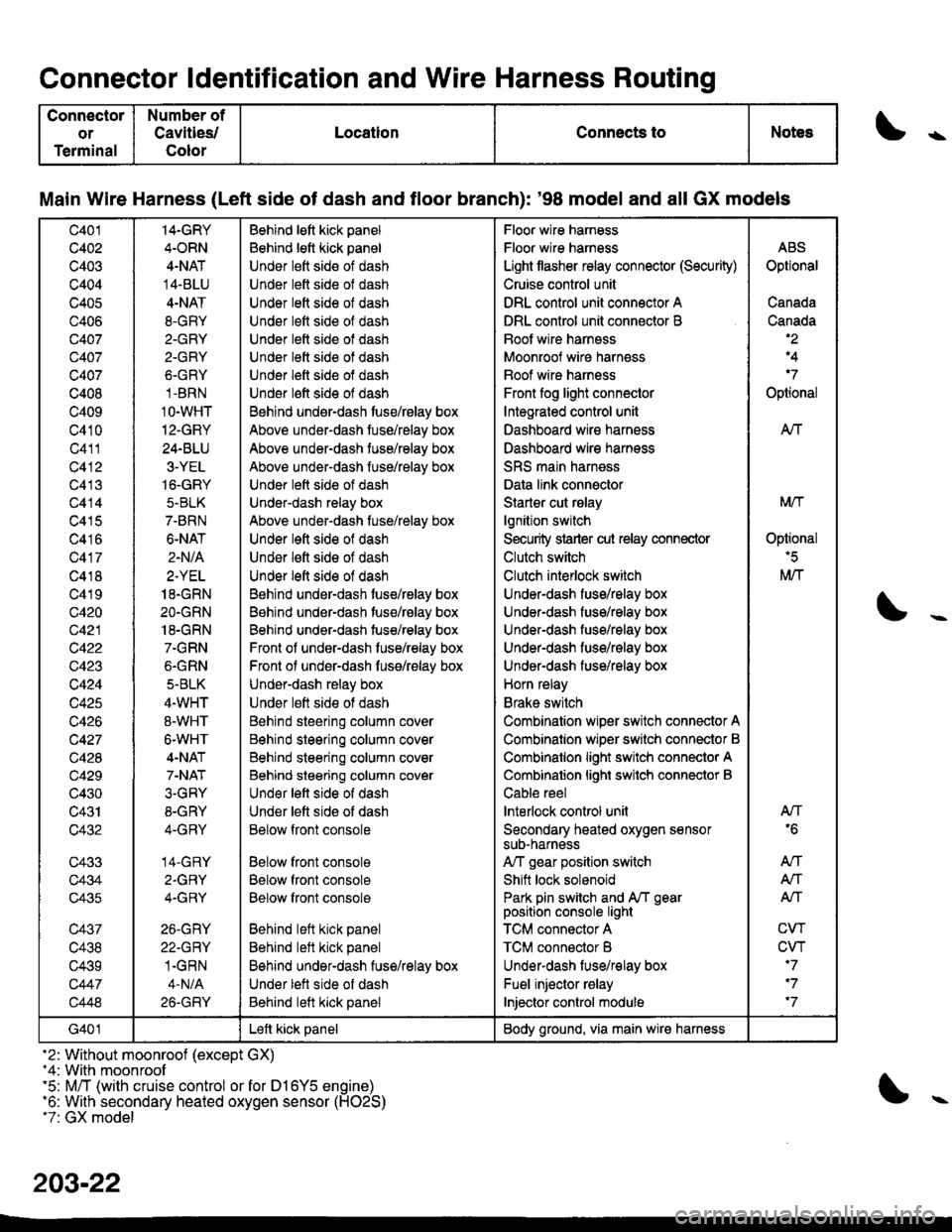
Connector ldentification and Wire Harness Routing
Connector
or
Terminal
Number of
Cavities/
Color
LocationConnects toNotess
Main Wire Harness (Left side of dash and tloor branch): '98 model and all GX models
c401
c402
c403
c404
c405
c406
Q407
c407
c407
c408
c409
c410
c411
c412
c413
c414
c415
c416
c417
c418
c419
c420
c421
c422
c423
c424
c425
c426
c427
c428
c429
c430
c431
c432
c433
c434
c435
c437
c438
c439
c447
c448
14-GRY
4.ORN
4-NAT
14-BLU
4-NAT
8.GRY
2.GRY
2-GRY
6.GRY
1-BRN
1O-WHT
12-GRY
24-BLU
3-YEL
16-GRY
5-BLK
7-BRN
6-NAT
2.N/A
2.YEL
18.GRN
2O.GRN
18-GRN
7.GRN
6.GRN
5-BLK
4.WHT
8-WHT
6-WHT
4-NAT
7-NAT
3.GRY
8-GRY
4-GRY
14-GRY
2.GRY
4.GRY
26.GRY
22-GRY
1.GRN
4-N/A
26-GRY
Behind lett kick panel
Behind lett kick panel
Under lett side of dash
Under lett side ol dash
Under lett side of dash
Under left side of dash
Under lett side of dash
Under lett side ot dash
Under left side of dash
Under l€ft side of dash
Behind undsr-dash tuse/rBlay box
Above under-dash tuse/relay box
Above under-dash tuse/relay box
Above under-dash fuse/relay box
Under lett side of dash
Under-dash relay box
Above under-dash tuse/relay box
Under left side of dash
Under lett side of dash
Under left side of dash
Behind under-dash tuse/relay box
Behind under-dash tuse/relay box
Behind under-dash tuse/relay box
Front of under-dash tuse/relay box
Front ol under-dash fuss/relay box
Under-dash relay box
Under lett side ot dash
Behind steering column cover
Behind steering column cover
Behind steering column cover
Behind steering column cover
Und€r left side of dash
Under lett side of dash
Below front console
Below front console
Below front console
Below front console
Behind left kick panel
Behind left kick panel
Behind under-dash fuse/relay box
Under lett side of dash
Behind left kick panel
Floor wire harness
Floor wire harness
Light tlasher relay connector (Security)
Cruise control unit
DRL control unit connector A
DRL control unit connector B
Boot wire harnsss
Moonroof wire harness
Boof wire harness
Front fog light connector
Integrated control unit
Dashboard wire harness
Dashboard wire harness
SRS main harness
Data link connector
Starler cut rslay
lgnition switch
Security strarter cut relay connector
Clutch switch
Clutch interlock switch
Under-dash fuse/relay box
Under-dash fuse/relay box
Under-dash fuso/rolay box
UndeFdash fuse/relay box
Under-dash fuse/relay box
Horn relay
Brake switch
Combination wiper switch connector A
Combinalion wiper srvitch connector B
Combinalion light switch connector A
Combinalion lighi swilch connector B
Cable reel
lnterlock control unil
Secondary heated oxygen sensorsuD-narness
A,/T gear position switch
Shift lock solenoid
Park pin switch and A/T gearposition console light
TCM connector A
TCM connector B
Underdash lus€/relay box
Fuel injector relay
Injector control module
ABS
Optional
Canada
Canada,2
,4
'7
Optional
AIf
Mtf
Oplional'5
M/T
AN'6
An
A,/T
Alf
CW
CVT'7
'7
'7
G401Left kick panelBody ground, via main wire harness
-2: Without moonroof (except GX)-4: With moonroof'5: M/T (with cruise control or for D16Y5 engine)'6: With secondary heated oxygen sensor (H02S)t7: GX model
203-22
Page 2165 of 2189
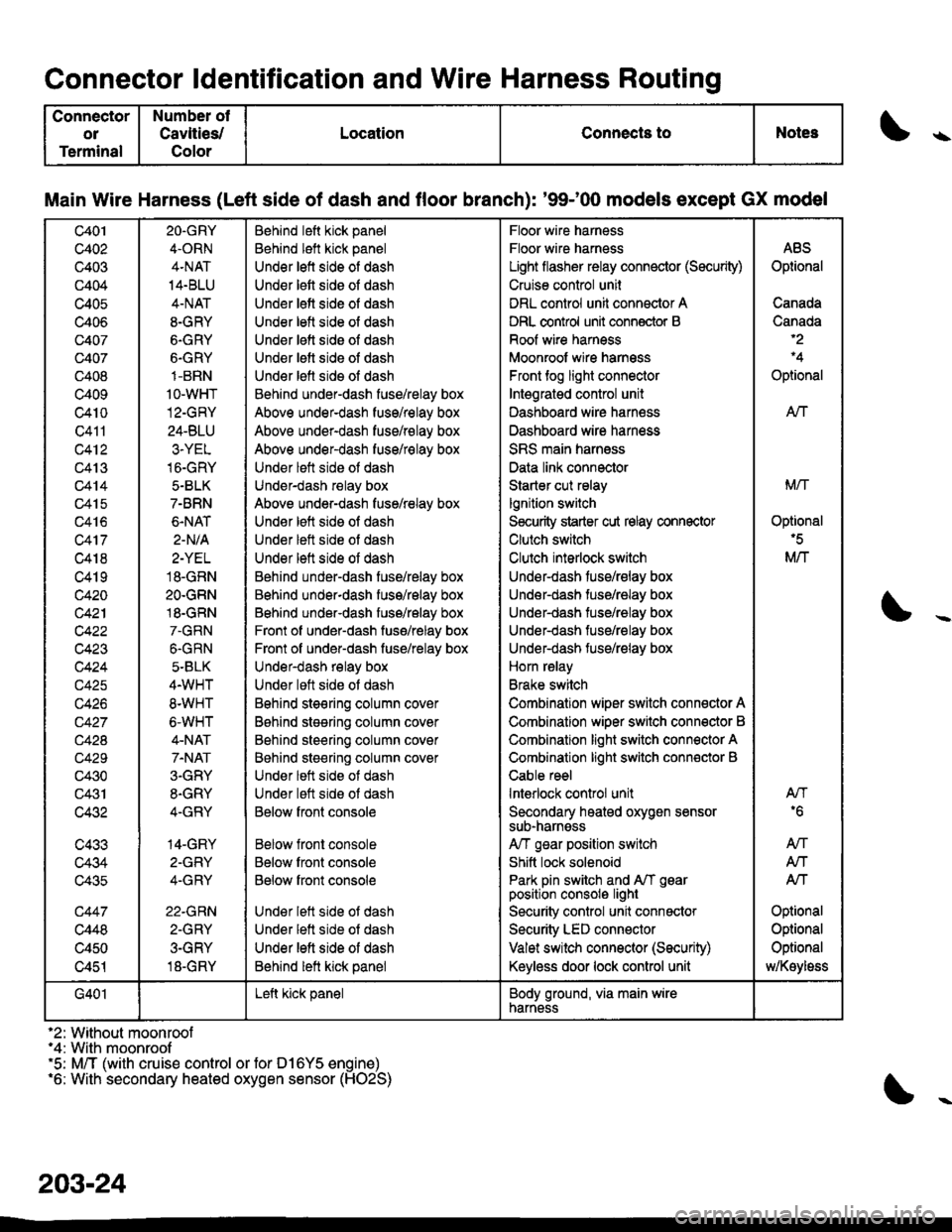
Connector ldentification and Wire Harness Routing
Connector
ol
Terminal
Number ot
Cavlties/
Color
LocationConnects toNotes\
Main Wire Harness (Left side of dash and floor branch): '9$00 models except GX model
c401
c402
c403
c404
c405
c406
c407
c407
c408
c409
c4t0
Q411
c412
c413
c414
c415
c416
c417
c418
c419
c420
c42'l
c423
c424
c425
c426
c42A
c429
c430
c431
c432
c433
c434
c435
c447
c448
c450
c451
2O.GRY
4.ORN
4.NAT
14.BLU
4-NAT
8-GRY
6.GRY
6.GRY
1-BRN
1o-wHT
12-GRY
24-BLU
3.YEL
16-GRY
5.BLK
7-BRN
6.NAT
2-N/A
2-YEL
18.GRN
2O.GRN
18.GRN
7.GRN
6.GRN
5-BLK
4.WHT
8.WHT
6-WHT
4-NAT
7.NAT
3.GRY
8.GRY
4-GRY
14-GRY
2-GFY
4-GRY
22.GRN
2-GRY
3-GRY
18-GRY
Behind left kick panel
Behind left kick panel
Under left side of dash
Under lett side oI dash
Under lett side of dash
Under letl side ol dash
Under lett side oI dash
Under letl side oI dash
Under lefl sids ol dash
Behind under-dash fuse/relay box
Above under-dash fuse/relay box
Above under-dash fuse/relay box
Above under-dash fuse/relay box
Under lett side ot dash
Under-dash relay box
Above under-dash fuse/relay box
Under left side of dash
Under left side ot dash
Under lett side of dash
Behind under-dash fuse/relay box
Behind under-dash fuss/relay box
Behind under-dash fuse/relay box
Front of under-dash fuse/relay box
Front of under-dash fuse/relay box
Under-dash relay box
Under loft side ot dash
Bohind steering column cov6r
B6hind stesring column cover
Behind steering column cover
Behind steering column cover
Under lett side ot dash
Under lett side ot dash
Below fronl console
Below front console
Below front console
Below front console
Under lett side ot dash
Under lett side of dash
Under left side of dash
Behind lett kick panel
Floor wire harness
Floor wire harness
Light flasher relay connector (Sscurity)
Cruise control unil
DRL control unit connector A
DRL control unit conn€ctor B
Roof wire harness
Moonroof wire harnsss
Front tog light connector
Intsgratgd control unit
Dashboard wire harn€ss
Dashboard wire harness
SRS main harness
Data link connector
Starter cut relay
lgnition switch
S€curity starter cut relay connector
Clutch switch
Clulch interlock switch
Under-dash fuse/relay box
Under-dash tuse/ralay box
Under-dash tuse/ralay box
Under-dash fuse/relay box
Under-dash fuse/relay box
Horn relay
Brake switch
Combination wiper switch connector A
Combination wiper switch conn€ctor B
Combination light switch connector A
Combination light switch conn€ctor B
Cable reel
lnterlock control unit
Secondary heated oxygen sensorsub-narnsss
A/T gsar position switch
Shitt lock solenoid
Park pin switch and A/T gearposition consolo light
Security control unit connactor
Security LED connector
Valet switch connector (Security)
Keyless door lock control unit
ABS
Optional
Canada
Canada
Optional
AN
Mrl
Optional'5
M/T
AN'6
An
Atf
Atf
Optional
Optional
Optional
MKoyloss
G401Left kick panelBody ground, via main wirenarness
'2: Without moonroof"4: With moonroof'5: M/T (with cruise control or for D16Y5 engine)'6: With secondary heated oxygen sensor (HO2S)
203-24
Page 2187 of 2189
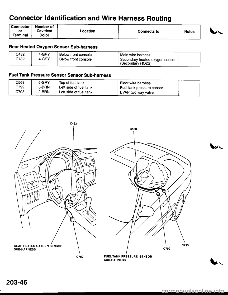
Connector ldentification and Wire Harness Routing
Connector
or
Terminal
Number ot
Cavities/
Color
LocationConnects toNotes
Rear Heated Oxygen Sensor Sub-harness
c782
4-GRY
4-GRY
Below front console
Below front console
Main wire harness
Secondary heated oxvoen sensor(Secondaiy HO2S) --
lrrr-
\y,.-
FUEL TANK PRESSURE SENSORSUB-TiARNESS
Fuel Tank Pressure Sensor Sensor Sub-harness
ucot'
c792
c793
6.GRY
3-BRN
2.BRN
Top of fuel tank
Left side of fuel tank
Left side of fuel tank
Floor wire harness
Fuel tank pressure sensor
EVAP two way valve
203-46
!'t